
Related Manuals for Ametek MTC-140 A


Summary of Contents for Ametek MTC-140 A
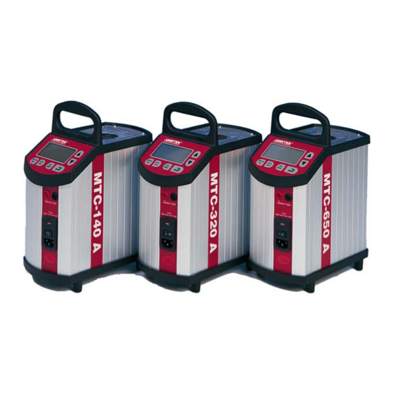
- Page 1 User Manual Temperature Calibrator MTC-140/320/650 A Copyright 2001 AMETEK DENMARK A/S...
- Page 2 The structure of the manual This user manual is aimed at users who are familiar with Ametek calibrators, as well as those who are not. The manual is divided into 10 chapters which describe how to set up, operate, service and maintain the calibrator. The technical specifications are described and accessories may be ordered from the list of accessories.
-
Page 3: Table Of Contents
List of contents Introduction ................4 Safety instructions ..............6 Setting up the calibrator ............10 3.1 Receipt of the calibrator.............. 10 3.2 Preparing the calibrator .............. 12 3.3 Choice of insertion tube .............. 13 3.4 Inserting the sensor ..............14 Operating the calibrator............17 4.1 Keyboard, display and connections.......... -
Page 4: Introduction
Congratulations on your new Ametek JF Instruments MTC-Calibrator! With the Ametek JF Instruments calibrator, you have chosen an extremely effective instrument which we hope will live up to all your expectations. Over the past many years, we have acquired extensive knowledge of industrial temperature calibration. - Page 5 CE-label Your new calibrator bears the CE label and conforms to the EMC directive and the Low- voltage Directive. Technical assistance Please contact the dealer from whom you acquired the instrument if you require technical assistance. Guarantee According to current terms of sale and delivery. This guarantee only covers defects in manufacture and becomes void if the instrument has been subject to unauthorised intervention and/or misuse.
-
Page 6: Safety Instructions
Safety instructions Read this manual carefully before using the instrument! Please follow the instructions and procedures described in this manual. They are designed to allow you to get the most out of your calibrator and avoid any personal injuries and/or damage to the instrument. Warning……... - Page 7 About insertion tubes and insulation plugs: • Never leave hot insertion tubes which have been removed from the calibrator unsupervised – they may constitute a fire hazard. If you intend to store the calibrator in the aluminium carrying case after use, you must ensure that the instrument has cooled to a temperature below 100°C/212°F before placing it in the carrying case.
- Page 8 100°C/212°F before you switch it off. Below 0°C/32°F (applies only to the MTC-140 A model) If the calibrator has reached a temperature below 0°C/32°F, ice crystals may form on the insertion tube and the well. This, in turn, may cause verdigris to form on the material.
- Page 9 Caution… About the use: • Do not use the instrument if the ventilator is out of order • Before cleaning the calibrator, you must switch it off, allow it to cool down and remove all cables. About the well, insertion tube and grid plate: •...
-
Page 10: Setting Up The Calibrator
You should receive: • 1 calibrator • 1 mains cable • 1 set of test cables (1 black, 1 red) • 3 pcs. insulation plugs for 6, 10, 13 mm sensors (MTC-140 A only) 26-07-2004 105337... - Page 11 • 1 insertion tube (user specified) • 1 tool for insertion tube • 1 traceable certificate • 1 user manual • 1 RS 232 serial cable • 1 CD-ROM containing software package “JofraCal”. When reordering, please specify the parts number found in the list of accessories, section 10.0.
-
Page 12: Preparing The Calibrator
Preparing the calibrator Warning • The calibrator must not be used in areas prone to explosives hazards. • The calibrator must be kept clear within an area of 20 cm on all sides and 1 metre above the calibrator. Note… The instrument must not be exposed to draughts. -
Page 13: Choice Of Insertion Tube
Caution… Do not use the instrument if the ventilator is out of order ensure a free supply of air to the ventilator located at the bottom of the instrument. check the voltage of the power control switch (on/off switch (230V/115V)). If the voltage of the power control switch differs from the line voltage, you must adjust the voltage of the power control switch as follows (see Fig. -
Page 14: Inserting The Sensor
Inserting the sensor Before inserting the sensor and switching on the calibrator, please note the following important warning: Warning • Never use heat transfer fluids such as silicone, oil, paste, etc. These fluids may penetrate the calibrator and cause damage or create poisonous fumes. Caution…... - Page 15 In order to spare the sensor and its connections it is recommended to use a heat protection shield (104216) at high temperatures. For MTC-140 A only. Check that the insulation plug fits the diameter of the sensor. Otherwise replace it.
- Page 16 If the design of the sensor permits it, you are advised to use an insulation tube and insulation as shown in Fig. 3. Fig. 3 26-07-2004 105337...
-
Page 17: Operating The Calibrator
Operating the calibrator Keyboard, display and connections Keyboard CALIBRATION INSTRUMENTS AUTO SWITCH TEST STEP MENU Fig. 4 Pos. Description LCD. SWITCH TEST button used to activate SWITCH TEST. The function automatically detects the opening/closing temperatures for thermostats. AUTO STEP button used to activate AUTO STEP. The function is used to switch between a series of set- temperatures automatically. - Page 18 UP ARROW button used to adjust temperature values (value increases) and to select menu options. Display Fig. 5 Pos. Description CHECKMARK displayed when the calibrator is stable. SWITCH TEST input open. SWITCH TEST input closed. AUTO STEP symbol used to indicate that the function is active (symbol flashes repeatedly).
- Page 19 Celsius temperature unit for top display. Used to display Read-temperature and parameters in the menu system. Connections Warning • The connectors, pos. 2 on the front panel, must NEVER be connected to a voltage source. • Thermostats must not be connected to any other voltage source during a test.
-
Page 20: Starting The Calibrator
Connection for RS232 cable. Note that all PC-equipment, which are connected to the calibrator must observe the directive IEC950. Starting the calibrator Switch the calibrator on using the power control switch (pos. 1 in Fig. 6). The instrument is initialised and the last calibration date is displayed: The calibration date will be displayed for approx. - Page 21 Press to accept the change or to cancel. The calibrator will now heat up/cool down. The top display continuously shows the read-temperature. The bottom display shows either the set-temperature or the estimated time in whole minutes until the calibrator will be stable: °C When the calibrator is stable the display will show the...
-
Page 22: Using The Switch Test
Using the SWITCH TEST SWITCH TEST automatically locates the switch temperature of a thermostat. You must enter a temperature range T , within which the switch temperature is expected to be found. You must also specify the slope rate to be used during the test in SETUP (the smaller the value, the more accurate the results of the test and the longer the test will take). - Page 23 Press to select the required T °C Press to accept your selection. Press to select the required T °C Press to accept your selection. The calibrator will now start working towards the T °C °C Once the T has been reached and the calibrator is stable, the instrument will emit an audible alarm and display the status for one second: °C...
- Page 24 The calibrator will now start working towards the T using the slope rate selected in SETUP. The flashing SWITCH TEST symbol indicates the current status: °C °C The instrument will check for changes in the SWITCH TEST. If no change has been detected by the time T is reached, the instrument will register an ERROR.
- Page 25 Press to display the hysteresis temperature: °C If a temperature has not been found, the instrument will display an “Error” (the “Hyste” temperature will also be shown as an “Error”): Press to end the SWITCH TEST. The instrument will store the T and T until the next time the SWITCH TEST is activated.
-
Page 26: Using The Auto Step
Using the AUTO STEP AUTO STEP is used to step automatically between a range of different calibration temperatures. This is useful when calibrating sensors in places which are hard to reach, and when calibrating sensors for which the output is displayed in a different location. The function can be illustrated using the following example: Fig. - Page 27 Press to select the required number of steps (minimum 2 steps, maximum 9 steps): Press to accept your selection. Press to select the required set-temperature for step 1: °C Press to accept your selection. Repeat the above procedure for all temperature steps. Press to accept your choices once you have adjusted the last temperature step.
- Page 28 The following will be displayed for one second to indicate that the calibrator is ready to work towards the set-temperature: °C The calibrator will now work towards the given set-temperature. An audible alarm will be emitted once the calibrator is stable. The calibrator will wait the specified amount of extra time.
-
Page 29: Using The Menu
Using the MENU Hold down for more than approx. 2 seconds: Press to select SETUP. Press to switch between the adjustable parameters: ⇑⇓ ⇑⇓ ⇑⇓ ⇑⇓ 105337 02 26-07-2004... -
Page 30: Adjusting The Temperature Unit
If you wish to exit SETUP, simply press The instrument will ignore all changes if you press when adjusting any of the parameters. Press to adjust the parameter. 4.6.1 Adjusting the temperature unit Press to switch between °C and °F: °C - and °F... -
Page 31: Adjusting The Max-Temperature
4.6.2 Adjusting the max-temperature Press to set the max-temperature in steps of 0.1°C or 0.1°F: °C If the current set-temperature is higher than the new max- temperature, you will need to adjust the set-temperature. The instrument will immediately begin to cool (if required) as soon as the new max-temperature is accepted. -
Page 32: Adjusting The Extra Stability Time
4.6.4 Adjusting the extra stability time The extra stability time is the amount of extra time you wish to elapse before the checkmark symbol is displayed after the calibrator has stabilised. Press to set the time to anywhere between 0 and 20 minutes: Press to accept your selection. -
Page 33: Simulation/Training
Simulation/training Hold down the buttons while you switch on the calibrator. The instrument will display the following screen: The instrument will then revert to the standard display. The calibrator’s simulation mode is used to train personnel in the use of the instrument, etc. The simulation setting differs from the standard setting as follows: •... -
Page 34: Storing And Transporting The Calibrator
Storing and transporting the calibrator Caution… The following guidelines should always be observed when storing and transporting the calibrator. This will ensure that the instrument and the sensor remain in good working order. Switch off the calibrator using the power control switch. Note that the calibration procedure may be interrupted at any time using the power control switch. - Page 35 100°C/212°F, you must wait until the instrument reaches a temperature below 100°C/212°F before you switch it off. Below 0°C/32°F (applies only to the MTC-140 A model) If the calibrator has reached a temperature below 0°C/32°F, ice crystals may form on the insertion tube and the well.
-
Page 36: Errors
• non-original parts are used in any way when operating the instrument. Ametek Denmark’s liability is restricted to errors which originated from the factory. If the calibrator detects an error during operation, the instrument will terminate all functions and display an error code:... - Page 37 Likely cause: An error has occurred in the control circuit. Solution: The calibrator should be returned to the manufacturer for service. Nothing happens when the power control switch (on/off switch) is pressed. Likely cause: There is no power to the calibrator. Solution: Check that the calibrator is correctly connected.
-
Page 38: Setting The Mains Voltage And Replacing The Fuses
Setting the mains voltage and replacing the fuses Warning • The fuse box must not be removed from the power control switch until the mains cable has been disconnected. • The two main fuses must be identical and correspond to the chosen voltage. -
Page 39: Returning The Calibrator For Service
Remove both fuses and insert two new fuses. These must be identical and should correspond to the line voltage. • MTC-140: 115V, 2AT = 105014 / 230V, 1AT = 105007 • MTC-320/650: 115V, 10AF = 60B302 / 230V, 5AF = 60B301 If the fuses blow immediately after you have replaced them, the calibrator should be returned to the manufacturer for service. - Page 40 Special requests:_____________________________________________________ ___________________________________________________________________ Safety precautions: if the product has been exposed to any hazardous substances, it must be thoroughly decontaminated before it is returned to Ametek. Details of the hazardous substances and any precautions to be taken must be enclosed. 26-07-2004...
-
Page 41: Maintenance
Maintenance Cleaning Caution… Before cleaning the calibrator, you must switch it off, allow it to cool down and remove all cables. Users should/must carry out the following cleaning procedures as and when required: • The exterior of the instrument - Clean using water and a soft cloth. -
Page 42: Adjusting And Calibrating The Instrument
Adjusting and calibrating the instrument You are advised to return the calibrator to Ametek Denmark A/S or an accredited laboratory at least once a year for calibration and adjustment. Alternatively, you can calibrate/adjust the calibrator yourself. You will need a reference thermometer and a reference sensor with a traceable certificate. - Page 43 Press to toggle between the different options: ⇑⇓ ⇑⇓ ⇑⇓ Press to accept your selection. To exit the adjustment/service mode, switch the instrument off and on again using the power control switch. 105337 02 26-07-2004...
-
Page 44: Adjusting The Calibration Date
8.2.1 Adjusting the calibration date Adjust the date by toggling through the available days, months and years. Begin by selecting the required day as shown below: Press to select the required day in the interval 1- Press to accept your selection. Press to select the required month from JAN / FEB / MAR / APR / MAY / JUN / JUL / AUG / SEP /... -
Page 45: Calibrating/Adjusting The Instrument
The instrument will disclose the first calibration temperature by displaying the text “TEMP.1 XXX°C” for approx. 1 second: Calibration temperature for calibrators: MTC-140 A -15°C / 5°F 20°C / 68°F 60°C / 140°F 100°C / 212°F... - Page 46 The instrument will now check whether the reference temperatures which have been entered are within the permitted tolerances. Permitted tolerances: • MTC-140 A, MTC-320 A: ±0,15°C / 0.27°F • MTC-650 A: ±0,25°C / 0.45°F 26-07-2004 105337...
- Page 47 If the instrument detects excessive deviations for one or more steps, it will show a screen reading =ERR. in the top of the display. The text AdJ. will flash in the bottom of the display to indicate that an adjustment is required (accept by pressing If the calibrator is found to be within the permitted tolerances, the instrument will display the text =OK at the top of the display.
- Page 48 If the new coefficients deviate by more than 4% from the standard values, the instrument will display an ERROR 2 in the display. The calculated coefficients will be ignored: Press to repeat the entire calibration/adjustment procedure. Press when Cont. is flashing to end the calibration/adjustment procedure and enter a new calibration date (see section 8.2.1).
-
Page 49: Technical Specifications
Technical specifications The illustration below shows the setup which forms the basis for the technical specifications. Fig. 12 105337 02 26-07-2004... - Page 50 All specifications are given with an ambient temperature of 23°C/73.4°F ± 3°C/5.4°F Specified at 115V / 230V Specifications Model MTC-140 A Max. Temperature : 140°C / 284°F Min. Temperature : -30°C / -22°F @ ambient temperature 0°C / 32°F -17°C / 1°F @ ambient temperature 23°C / 73°F -2°C / 28°F @ ambient temperature 40°C / 104°F...
- Page 51 Time to stability 5 min. Cooling, 25 min. max. to min. MTC-320 A Max. Temperature : 320°C / 608°F Min. Temperature : 33°C / 91°F @ ambient temperature 23°C / 73°F Display resolution : 0.1°C / 0.1°F Stability ±0.1°C / ±0.18°F Accuracy ±0.5°C / ±0.9°F Heating,...
- Page 52 Electrical specifications Specifications Model MTC-140 A Power supply [VAC], 115VAC, 45-65Hz 90-127 230VAC, 45-65Hz 180-254 Power consumption, [VA] : Test voltage, switch test [V] MTC-320 A Power supply [VAC], 115VAC, 45-65Hz 90-127 230VAC, 45-65Hz 180-254 Power consumption, [VA] : 1150...
- Page 53 Mechanical specifications Specifications Model MTC-140 A Weight 6.5 Kg. / 14.3 Lbs. Dimensions HxWxL 325 x 139 x 241 mm / 12.80 x 5.47 x 9.49 inch Operating temp. 0 - 40°C / 32 - 104°F Storage temp. -20 - 50°C / -4 - 122°F...
- Page 54 Dimensions HxWxL 325 x 139 x 241 mm / 12.80 x 5.47 x 9.49 inch. Operating temp. 0 - 40°C / 32 - 104°F Storage temp. -20 - 50°C / -4 - 122°F Humidity range 0-90% Rh Protection class IP10 Additional data - directives observed EMC directives 89/336 / EEC EN61326 (1997)
-
Page 55: 10.0 List Of Accessories
Accessories Parts no. Fuse 115V, 10AF 60B302 (MTC-320/650 A) Fuse 230V, 5AF 60B301 (MTC-320/650 A) Fuse 115V, 2AT 105014 (MTC-140 A) Fuse 230V, 1AT 105007 (MTC-140 A) User manual 105337 Tool for insertion tube 60F170 Heat protection shield 104216 Alu. carrying case, high... - Page 56 Insulation 30 x 30 mm 105173 Cleaning brush, 4 mm 122832 Cleaning brush, 6 mm 60F174 Cleaning brush, 8 mm 122822 Set of insulation plugs (MTC-140 A only) 123469 Set of test cables 104203 RS232 serial cable 105366 JofraCal PC software 124915...
- Page 57 PARTS NO. FOR STANDARD INSERTION TUBES Sensor MTC-140 A MTC-320 A MTC-650 A size 3 mm 123428 123436 123444 4 mm 60F451 100177 100196 5 mm 123429 123437 123445 6 mm 60F453 100179 100198 7 mm 123430 123438 122516 8 mm...
Need help?
Do you have a question about the MTC-140 A and is the answer not in the manual?
Questions and answers