Table of Contents
Advertisement
Quick Links
Advertisement
Table of Contents

Related Manuals for Ametek Jofra MTC-650 A MKII


Summary of Contents for Ametek Jofra MTC-650 A MKII
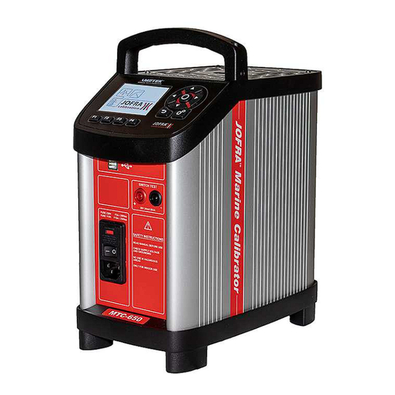
- Page 1 User Manual Marine Temperature Calibrator Jofra MTC-650 A MKII...
- Page 2 User Manual Marine Temperature Calibrator JOFRA MTC-650 A MKII Copyright 2019 AMETEK Denmark A/S...
-
Page 3: Table Of Contents
List of contents 1.0 Introduction ........................3 1.1 List of equipment received......................3 2.0 Safety instructions ......................4 3.0 Setting up the calibrator ....................7 3.1 Before use ..........................7 3.2 Keypad - Functions ........................ 10 3.3 Display ........................... 10 3.4 Connections ........................... -
Page 4: Introduction
Introduction The MTC-calibrator is a fast, timesaving, and reliable true industrial temperature calibrator designed for on-site use calibrating temperature sensors and temperature switches. Read this manual carefully before using the instrument and make sure that all safety instructions and warnings are observed. List of equipment received When you receive the instrument, the following should be enclosed: •... -
Page 5: Safety Instructions
Safety instructions Read this manual carefully before using the instrument! In order to avoid any personal injuries and/or damage to the instrument all safety instructions and warnings must be observed. Disposal – WEEE Directive These calibrators contain Electrical and Electronic circuits and must be recycled or disposed of properly (in accordance with the WEEE Directive 2012/19/EU). - Page 6 • Remember to use appropriate protective equipment or get help when carrying the calibrator (for a longer distance) in order to prevent injuries from dropping the calibrator. About the front panel: • The connectors, on the front panel of the calibrator, must NEVER be connected to a voltage source.
- Page 7 About the well, insertion tube and grid plate: • The well and the insertion tube must be clean and dry before use. • Do not pour any form of liquids into the well. It might damage the well or cause a hazard.
-
Page 8: Setting Up The Calibrator
Setting up the calibrator ENVIRONMENTAL SPECIFICATIONS Ambient operating temperature range: 0-50°C / 32-122°F Storage temperature range: -20-50°C / -4-122°F Humidity range: 5-90% RH, non-condensing IP protection class: IP10 Altitude: 0-2000 m Electromagnetic Compatibility: Tested for use in domestic establishment and in establishments directly connected to low voltage power supply network which supplies buildings used for domestic purposes as well as in an... - Page 9 • Always position the calibrator to enable easy and quick disconnection of the power source (mains inlet socket). • The calibrator must be kept clear within an area of 20 cm on all sides and 1 metre above the calibrator due to fire hazard. Caution –...
- Page 10 Warning The two main fuses must have the specified current and voltage rating and be of the specified type. The use of makeshift fuses and the short-circuiting of fuse holders are prohibited and may cause a hazard. Check that the earth connection for the instrument is present and attach the cable. Place the sensor (pos.
-
Page 11: Keypad - Functions
Keypad - Functions Function keys - F1, F2, F3, F4 For operating the horizontal menu. Arrow Keys Navigation mode: Use the four keys to move the cursor in the desired direction. Edit mode: The Up and Down Arrow keys scroll through the lists of options. -
Page 12: Connections
4) Reference sensor info Shows the reference sensor selected. 5) Memory reading Shows the current memory selected from the System menu. 6) Warning/Error symbols. If a warning or an error symbol occurs during operation, action needs to be taken. 7) Real Time Clock and date display. 8) True temperature reading Shows the numeric value of the temperature being measured. - Page 13 • Indicates that the “stable” situation is achieved and for how long the calibrator has been stable. When the calibrator has been stable for more than 99 minutes, only the stable sign is displayed (time is no longer displayed). When the instrument is heating up and cooling down indication of this will be shown as following symbols: •...
-
Page 14: 4.0 Operating The Calibrator
4.0 Operating the calibrator Operating principle The calibrator is operated using the Functions keys, the Arrow keys and the Action/Enter key. 1. Press the Functions keys to operate the horizontal menu bar. 2. Press any of the (Arrow) keys to enter Navigation Mode. Editable fields will be highlighted in blue. - Page 15 Note… • If the current set-temperature is higher than the new max-temperature, you will need to adjust the set-temperature. The instrument will immediately begin to cool (if required) as soon as the new max-temperature is accepted. • The calibration interval can be set between 1 and 99 months. When the calibration interval is exceeded, a yellow warning symbol will appear in the upper part of the display.
-
Page 16: Starting The Calibrator
1. Use the (Up) and (Down) Arrow keys to select the Memory-setup you want to modify, and press (Save). The new configuration is now saved. 2. You can change the name of the highlighted saved setup by pressing (Enter), and then using the (Up) and (Down) Arrow keys to change the characters. -
Page 17: Selecting The Set-Temperature
Selecting the set-temperature Note… Temperature range is limited by Min. SET Temp. and Max. SET Temp. settings editable in the System Settings menu. The set-temperature can be entered both manually and by selecting a preset temperature. 1. For manually use press (Set) 2. -
Page 18: Editing The Preset Set-Temperature
4.5.1 Editing the preset set-temperature It is possible to change the preset set temperature to whatever value desired. 1. Press (Preset). 2. Press one of the (Arrow) keys and an editable field displaying the preset set temperatures appears. 3. Navigate to the set temperature field using the arrows. 4. -
Page 19: The Calibrator's Auto Step Procedure
• Step values: must be set within the sensors permitted range. 3. Press (F4) to start the Auto Step test. The Auto Step test is now in progress. While the Auto Step test is in progress, 4 options are available: •... -
Page 20: Switch Test Function
Switch Test function Switch Test automatically locates the switch temperature of a thermostat. Three parameters are required: • Start temperature (T • End temperature (T • Rate of change in temperature pr. minute (Rate). Dead band of a thermostat can also be determined here. Where the dead band determines the tolerance between the upper switch temperature and the lower switch temperature of the thermostat. -
Page 21: The Calibrator's Switch Test Procedure
• Dead band : To determine dead band, toggle between "Yes" (a two-way- temperature measurement) and "No" (a one-way-temperature measurement). A dead band result is only measured when dead band is set to “Yes”. • Rate : The permitted range is 0.01 - 10.0°C/min. / 0.02 - 18.0°F/min. - Page 22 5) When dead band is not selected (single temperature change) (the graphic indicates the choice), the finished switch test result is displayed. When dead band is selected (two switch changes), the calibrator starts working towards T at the specified Rate. 6) Normally, the thermostat changes state before T is achieved.
-
Page 23: Setting The Mains Voltage And Replacing The Main Fuses
Setting the mains voltage and replacing the main fuses Replacing the main fuses Warning • The calibrator must be switched off before any attempt to service the instrument is made. There are no user serviceable parts inside the calibrator. • The fuse box must not be removed from the power control switch until the mains cable has been disconnected. -
Page 24: After Use
After use Storing and transporting the calibrator Caution… The following guidelines should always be observed when storing and transporting the calibrator. This will ensure that the instrument and the sensor remain in good working order. Warning • The calibrator must be switched off before any attempt to service the instrument is made. -
Page 25: Switching Off The Calibrator
Switching off the calibrator 1. Switch off the calibrator using the power control switch. Note that the calibration procedure may be interrupted at any time using the power control switch. Switching off the calibrator during the calibration process will not damage either the instrument or the sensor. - Page 26 Warning • Never leave hot insertion tubes which have been removed from the calibrator unsupervised – they may constitute a fire hazard or personal injury. If you intend to store the calibrator in the optional aluminium carrying case after use, you must ensure that the instrument has cooled to a temperature below 50°C/122°F before placing it in the carrying case.
- Page 27 Tel +86 10 8526 2111 ext. 19 general.lloyd-instruments@ametek.fr crystal@ametek.com jofra@ametek.com stc.china@ametek.com Germany - Florida Tel +49 (0)2159 9136 510 Tel +1 (800) 527 9999 info.mct-de@ametek.de cal.info@ametek.com Information in this document is subject to change without notice. ©2019, by AMETEK, Inc., www.ametek.com. All rights reserved.
Need help?
Do you have a question about the Jofra MTC-650 A MKII and is the answer not in the manual?
Questions and answers