Table of Contents
Advertisement
M a n u a l
F o r
O p e r a t i o n
Magnetic field testing
50 / 60 Hz power magnetic field
Pulsed magnetic field
MFC 1000.1, MFC 1000
MFT 30
current transformer
MFT 100-120
current transformer (120 V)
MFT 100-230
current transformer (230 V)
Version: 1.20 / 05.11.2020
Replaces: 1.11 / 03.03.2020
Filename:
UserManual-MFC1000_MFT30-100-E V1.20.docx
Printdate: 05.11.2020
Antenna
EN/IEC 61000-4-8
EN/IEC 61000-4-9
EN 61000-6-1
EN 61000-6-2
Advertisement
Table of Contents

Related Manuals for Ametek MFC 1000.1


Summary of Contents for Ametek MFC 1000.1
- Page 1 EN/IEC 61000-4-8 EN/IEC 61000-4-9 EN 61000-6-1 Magnetic field testing EN 61000-6-2 50 / 60 Hz power magnetic field Pulsed magnetic field MFC 1000.1, MFC 1000 Antenna MFT 30 current transformer MFT 100-120 current transformer (120 V) MFT 100-230 current transformer (230 V) Version: 1.20 / 05.11.2020...
- Page 2 4153 Reinach BL1 Schweiz Phone : +41 61 204 41 11 Fax : +41 61 204 41 00 URL : http://www.ametek-cts.com Copyright © 2020 AMETEK CTS GmbH All right reserved. Specifications subject to change Operating Manual V 1.20 2 / 37...
-
Page 3: Table Of Contents
Calibration and Verification ....................... 35 5.2.1. Factory calibration ..........................35 5.2.2. Guideline to determine the calibration period of AMETEK CTS instrumentation ......35 5.2.3. Calibration of Accessories made by passive components only: ............35 5.2.4. Periodically In-house verification ...................... 35 5.3. -
Page 4: Model Overview
AMETEK CTS H-Field Test Model Overview 1.1. Generators To realize the different test procedures the following AMETEK CTS generators are required: NetWave7 preferred ac source IEC 61000-4-8 compact NX 5/7 series preferred test generator NSG 30x0A series preferred test generator... - Page 5 AMETEK CTS H-Field Test Motor variac 0-260V/16A variac NX1-260-16 with compact NX5/NX7 Motor variac 0-260V/16A VAR 3005A-S16 with NSG 3040A/3060A AC-DC source Netwave 7 Netwave 7 Operating Manual V 1.20 5 / 37...
- Page 6 AMETEK CTS H-Field Test Generators The most comfortable test equipment to conduct magnetic field tests as per IEC 61000-4-8 and IEC 61000-4-9 is the compact generator type compact NX5 / compact NX7, NSG 3040A, NSG 3060A series. For easy testing 50Hz / 60Hz magnetic field an ac source like NetWave is very comfortable.
-
Page 7: Magnetic Field Antenna
H Field [ A ] Antenna Magnetic field antenna MFC 1000.1 Plugs for connect MFC 1000.x The magnetic field antenna has two different types of connectors. Two sets of parallel safety banana connectors for the range of 30 A/m and an optional set of connectors for higher currents. -
Page 8: Cable To The Magnetic Field Antenna
AMETEK CTS H-Field Test 1.3. Cable to the magnetic field antenna According to the standard the cable between the magnetic field generator (Transformer) and Antenna should be Twisted Max. 2 m as per IEC 61000-4-8 Max. 3 m as per IEC 61000-4-9 cables have a length of 2 m ... -
Page 9: Current Transformers
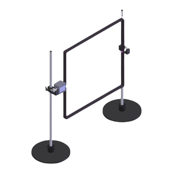
AMETEK CTS H-Field Test 1.4. Current transformers General setup for magnetic field Two different current transformers are available: MFT 30 to generate continuous magnetic fields up to 30 MFT 100 to generate continuous magnetic fields from 80 up to 100 A/m and short time magnetic fields up to 1000 A/m. -
Page 10: Current Transformer Mft 30
AMETEK CTS H-Field Test 1.4.2. Current transformer MFT 30 The MFT 30 has two current ranges 3 A and 30 A. The ranges can be select with the switch at the rear side of the MFT 30. The two parallel current outputs to the antenna can be used with connectors for 4 mm or 50 A. - Page 11 AMETEK CTS H-Field Test Connection transformer - antenna: Use two parallel, 2 m long safety banana cables H Field up to30A/m current transformer cable antenna The Transformer Factor is influenced by the heating of the cables. For continuous testing with magnetic fields > 10 A/m check the current with a current probe.
-
Page 12: Current Transformers Mft 100-120/230
AMETEK CTS H-Field Test 1.4.3. Current transformers MFT 100-120/230 The MFT 100 is used for high magnetic fields from 80 A/m up to 1000 A/m. The transformer is rated for constant current of 250 A. An internal overtemperature sensor will protect the transformer. -
Page 13: Test Setup
AMETEK CTS H-Field Test Test Setup Possible test setups for H-field tests Motorvariac and compact NX / NSG 30x0A The generator controls the motorvariac via the 0-10 V analog signal. The selected voltage will generate the current in the antenna loop. -
Page 14: Magnetic Field As Per Iec 61000-4-8
AMETEK CTS H-Field Test 2.1.1. Magnetic field as per IEC 61000-4-8 The menu offers different test routines for power frequency magnetic field testing. Main menu ac powered magnetic field The Magnetic Field menu offers different test routines for pulsed magnetic testing. -
Page 15: Required Device Settings To Perform A Power Frequency Magnetic Field Test
AMETEK CTS H-Field Test 2.1.2. Required device settings to perform a power frequency magnetic field test For perform a 50/60 Hz magnetic field test, the NX5 generator must be configured with the used hardware in the menu: Menu / SETUP / Equipment 1. -
Page 16: Test Setup With Mft 30 For H-Fields Up To 30 A/M
AMETEK CTS H-Field Test 2.1.3. Test setup with MFT 30 for H-Fields up to 30 A/m Variant 1: variac NX 1-260-xx not Rack connected (MFT 30) Disable option “Rack connected” In this case the switch PF1 is not used and remains open, the test is switched via the switch PF2... - Page 17 AMETEK CTS H-Field Test Variant 2: variac NX 1-260-xx Rack connected (MFT 30) Enable option “Rack connected” In this case, the rack cabling does not need to be changed, the PF1 connection between variac NX1-260-xx and the compact NX can remain. However, switch PF1 remains open, the test is still switched via switch PF2.
-
Page 18: Test Setup With Mft 100 For H-Fields Up To 1.000 A/M
AMETEK CTS H-Field Test 2.1.4. Test setup with MFT 100 for H-Fields up to 1.000 A/m Variant 1: variac NX 1-260-xx not Rack connected (MFT 100) Disable option “Rack connected” Switch PF2 is used to switch the relay in the MFT 100 with the mains voltage, thus switching the test on/off. - Page 19 AMETEK CTS H-Field Test Variant 2: variac NX 1-260-xx Rack connected (MFT 100) Enable option “Rack connected” In this case the relay in the MFT 100 is switched on/off via the PF1 (compact NX) switch. The connection from the variax NX (PF2) to the compact NX (PF2) remains and does not need to be changed. The PF2 switch in the compact NX remains open and is not used for this test.
-
Page 20: Iec 61000-4-8 50/60 Hz Magnetic Field With Nsg 3040A/3060A
AMETEK CTS H-Field Test 2.2. IEC 61000-4-8 50/60 Hz magnetic field with NSG 3040A/3060A The Power magnetic menu offers different test routines for magnetic field testing. Click into Power Magnetic Field menu loads the last used menu of the following routines below. -
Page 21: Required Device Setting To Perform A Power Frequency Magnetic Field Test
For more information see chapter 1.4.2 current transformer MFT 30 Menu / SETUP / EXTERNAL COUPLERS 3. Magnetic field antenna: - MFC 1000.1 The coil or antenna factor is defined as follow: H-field antenna [A / m] Coil factor = I antenna [A] For more information see chapter 1.2 Magnetic field... -
Page 22: Test Setup For Power Frequency Magnetic Field Test
Test setup with MFT 30 for H-Fields up to 30 A/m Schematics Test setup Schematics and Test setup with NSG 3040A, VAR 3005A-S16, MFT 30 and MFC 1000.1 Options required for magnetic field tests as per IEC 61000-4-8 - External variable motor variac VAR 3005A-S16 - External magnetic field antenna MFC 1000.x... -
Page 23: Test Setup With Mft 100 For H-Fields Up To 1.000 A/M
Test setup with MFT 100 for H-Fields up to 1.000 A/m Schematics Test setup Schematics and Test setup with NSG 3040A, VAR 3005A-S16, MFT 100 and MFC 1000.1 Options required for magnetic field tests as per IEC 61000-4-8 - External variable motor variac VAR 3005A-S16 - External magnetic field antenna MFC 1000.x... -
Page 24: Verification Of The Generator Characteristic As Per Iec 61000-4-8
AMETEK CTS H-Field Test 2.3. Verification of the generator characteristic as per IEC 61000-4-8 The output current shall be measured with the coil connected. The connection to the antenna shall be made of drilled cables of max 3 m length and with a sufficient cross-section. -
Page 25: Iec 61000-4-9 Pulsed Magnetic Field With Compact Nx5/Nx7
AMETEK CTS H-Field Test 2.4. IEC 61000-4-9 Pulsed magnetic field with compact NX5/NX7 Main menu Magnetic Field separated to “Power frequency” and “Pulsed” Select “Pulsed” to perform tests according IEC 61000-4-9. 2.4.1. Magnetic field as per IEC 61000-4-9 Pulse magnetic fields are generated by lightning strokes on buildings and other metal structures including aerial masts, earth conductors and earth networks and by initial fault transients in low, medium and high voltage electrical systems. -
Page 26: Setup Pulsed Magnetic Field
AMETEK CTS H-Field Test Extended Tests The operator can select between various preprogrammed test routines which helps to accelerate testing and which are very helpful especially during design. User test routines The user defined library where all created magnetic field tests are stored. -
Page 27: Iec 61000-4-9 Pulsed Magnetic Field With Nsg 3040A/3060A
AMETEK CTS H-Field Test 2.5. IEC 61000-4-9 Pulsed magnetic field with NSG 3040A/3060A The menu offers different test routines for pulsed magnetic field testing. Main menu Pulsed Magnetic Field The Magnetic Field menu offers different test routines for pulsed magnetic testing. -
Page 28: Quick Start
AMETEK CTS H-Field Test 2.5.1. Quick Start Easy and very fast operation of all standard functions of the equipment. The latest simulator settings are stored automatically and will be recalled when Quick Start is next selected. Quick Start Menu Quick Start testing for 100 A/m 2.5.2. -
Page 29: User Test Routines
AMETEK CTS H-Field Test 2.5.2.1. Pulsed Magnetic Field Standard library The pulsed magnetic field standard menu offers a list of standards of edition 1 (2001) and edition 2 (2016). The standard name has the character: [Standard Family], [Standard number], [year]) The standard IEC 61000-4-9 Ed2 (2016) requires mandatory an 18 F capacitor, that is automatically... -
Page 30: Setup Pulsed Magnetic Field
AMETEK CTS H-Field Test Only coils with 1 turn can be used for pulsed magnetic field application. Caution 2.5.5. Setup pulsed magnetic field Disconnect all power cables on the rear side at the Test supply plugs. PF1, PF2 and N Don’t touch the antenna during the test! -
Page 31: Iec 61000-4-10 Damped Magnetic Field
AMETEK CTS H-Field Test 2.6. IEC 61000-4-10 Damped Magnetic Field This part is realized with the OCS500N6/N6F generator. Characteristic of the generator (Damped Oscillatory Magnetic Field) The generator is specified as per IEC 61000-4-10 and the antenna is connected to the output HV - COM... -
Page 32: Technical Data
AMETEK CTS H-Field Test Technical data Magnetic field antenna MFC 1000 MFC 1000.1 , 1 m x 1 m , 1 m x 1 m Number of turns 1, (single turn) 1, (single turn) Antenna factor 0,87/m 0,87/m 8/20 s pulse current up to 2.000 A 8/20 s pulse current up to 2.000 A... -
Page 33: Standards
AMETEK CTS H-Field Test Standards Magnetic field tests are specified in three different standards, depending on the kind of phenomena which shall be simulated. IEC 61000-4-8 IEC 61000-4-9 IEC 61000-4-10 50/60Hz magnetic field pulsed magnetic field Damped oscillatory magnetic field 4.1. -
Page 34: Iec 61000-4-10
AMETEK CTS H-Field Test 4.3. IEC 61000-4-10 Damped oscillatory fields mainly are related by operation of high voltage bus-bar isolators. Field strength of up to several 100 A/m can be detected. Damped oscillatory Level Magnetic field strength [A/m] -------- --------... -
Page 35: Maintenance And Service
Our International Service Departments and our QA Manager are frequently asked about the calibration interval of AMETEK CTS equipment. AMETEK CTS doesn’t know each customer’s Quality Assurance Policy, nor do we know how often the equipment is used and what kind of tests are performed during the life cycle of a test equipment. Only the customer knows all the details and therefore the customer needs to specify the calibration interval for his test equipment. -
Page 36: Maintenance
AMETEK CTS H-Field Test 5.3. Maintenance The antenna and power transformers are maintenance-free. 5.3.1. Cleaning Never scratch objects or caustic chemicals for cleaning. The housing with a soft moist cloth, wipe and dry them afterwards. Delivery groups Identical accessory parts are delivered only once if several devices are ordered. The delivered packing list is in each case valid for the delivery. -
Page 37: Appendix
CE directives listed below using the relevant section of the following EC standards and other normative documents. Product‘s name: Magnetic field test equipment Model Number(s) MFC 1000, MFC 1000.1 MFT 30 MFT 100 Low Voltage Directive 2014/35/EU Standard to which conformity is declared:...
Need help?
Do you have a question about the MFC 1000.1 and is the answer not in the manual?
Questions and answers