amiad TEQUATIC PLUS F-150 C Series Installation & Operation Manual
Hide thumbs
Also See for TEQUATIC PLUS F-150 C Series:

Subscribe to Our Youtube Channel
Related Manuals for amiad TEQUATIC PLUS F-150 C Series


Summary of Contents for amiad TEQUATIC PLUS F-150 C Series
- Page 1 Installation & Operation Manual TEQUATIC™ PLUS F-150, C-Series Registered Patent Installation & Operation Manual | TEQUATIC™ PLUS...
-
Page 2: Disclaimer
Amiad or consult Amiad experts or its authorized representatives if you have any questions. Amiad Water Systems Ltd. D.N. Galil Elyon 1, 1233500, Israel Tel: 972 4 690 9500 | Fax: 972 4 814 1159 Email: info@amiad.com... -
Page 3: Table Of Contents
Controls Overview .................... Error! Bookmark not defined. Main Settings ..............................14 Admin Settings .............................. 18 Start-Up and Operation ..........................23 Maintenance ..............................34 Troubleshooting ............................38 Spare Parts..............................41 Amiad Limited Warranty ..........................47 Installation & Operation Manual | TEQUATIC™ PLUS | Table of Contents... -
Page 4: Introduction
Introduction Safety Information Symbols It is important for you to read and understand the information in this manual prior to installation and operation of TEQUATIC™ PLUS filter skids. This manual contains information designed to facilitate operator safety and prevent problems. The symbols below are used to reinforce key messages throughout. - Page 5 Property and Equipment Messages ➢ This equipment is not rated for hazardous locations. ➢ Avoid electrical hazards and damage to equipment. Install in an area where water leakage from vessel or piping will not damage sensitive equipment. ➢ Never operate the system at pressures and temperatures in excess of the specified rating. ➢...
- Page 6 Parameter Value Max Inlet Pressure 80 psi (5.5 bar) Process Water Temperature 45 - 140˚F (7-60˚C)1,2 Ambient Temperature Range 32 - 100˚F (0 - 37.8˚C) Maximum Altitude 6500 Ft (2000m) Relative Humidity 95%, non-condensing pH Range 5.0 - 9.0 continuous Electrical, C-Series 380-480V, 50/60Hz, 3-phase, 25A Recirculation Pump...
-
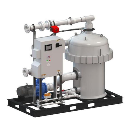
Page 7: System Overview
4. Flow rate will vary depending on water quality. System Overview Control System The controller provides the operator interface for the system and controls the operation of the various valves, sensors, and pump. The PLC and VFD are located in the main enclosure with the main disconnect and the HMI screen. -
Page 8: Installation
Installation System Configurations The configuration of the TEQUATIC™ PLUS F-150 C-Series skid will depend on the purpose of the system as well as the scale. The system can be a single skid, or multiple parallel skids for larger scale. The optimal configuration will be site-specific, but should include some of the following aspects: Parallel Systems: When parallel systems are employed, it is recommended that valving be utilized on all lines to permit isolation of any single system for maintenance. - Page 9 Site Preparation Before the physical installation of the system, it is important to make sure the installation area is properly configured for accessing the system. The allotted space should include the physical requirements of the equipment plus additional space for working and maintenance clearance. At a minimum, the area in front of the control panel should be left open to permit the operator access for daily operation.
- Page 10 Hoisting Hoisting and transporting the skid must be completed in a manner that maintains stability and does not cause damage to the components. The primary lifting method is intended to be forklift or pallet jack. Note the following for lifting and transporting: ➢...
- Page 11 Electrical ➢ The system requires a 3-phase, grounded supply circuit. ➢ Make sure the circuit is installed in accordance with all applicable electrical codes. ➢ The main disconnect lugs are rated for stranded copper, up to 3/0 maximum conductor size. All conductors must be rated for 75°C.
- Page 12 Feed Pump The filter skid is designed to operate with a constant feed pressure between 30 and 80 psi that is maintained as flow changes with minimal pressure variation. In the case where this type of feed water is not available a dedicated feed pump should be used. The feed pump should be pressure controlled using a VFD with a pressure sensor and a closed loop, PID feedback system.
-
Page 13: Controls Overview
Controls Overview The TEQUATIC™ PLUS F-150 C-Series Skid system is operated with a PLC controller and touch screen display. The display provides status information about the system and also the primary operator interface. The functions of the operator interface are presented on various screens, which are described in the sections below. - Page 14 Manual Controls Individual pumps and valves may be manually operated from the home screen. This can be helpful for tuning the system or for troubleshooting and testing devices. To manually operate a device, touch the icon representing the pump or valve. A pop-up dialog will be displayed.
-
Page 15: Main Settings
Main Settings Screen The main settings screen provides navigation to each of the individual setting screens. The individual setting screens are listed below and in the subsequent sections. Startup Settings, page 14 Valve Settings, page 15 Tank Settings, page 16 DP/Pressure Settings, page 17 RPM Settings, page 17 CIP, Clean In Place, page 18... - Page 16 Valve Settings This screen sets the basic parameters for any installed valves. Touch the valve name to select which of the installed valves to view the settings for. This will be Filtrate Valve (Manual, DP, or Flow) and Purge Valve. ➢...
- Page 17 Tank Settings This screen sets the basic parameters for any installed tank level switch. The switches must be dry contact (open or closed circuit) type switches. The logic for switch condition to run condition can be set according to the switch setup. ➢...
- Page 18 DP/Pressure Settings The DP/Pressure settings screen lists various parameters related to the filter operation and associated alarm thresholds. ➢ High DP: This setting determines the differential pressure value necessary to trigger a cleaning cycle. The differential pressure represents how much resistance to water flow is through the filter.
-
Page 19: Admin Settings
This screen sets the general parameters of the system, which are described in the sections below. Notice: Access to this section is restricted to only administrator access levels and should only be adjusted by an Amiad technician. Installation & Operation Manual | TEQUATIC™ PLUS | Controls Overview... - Page 20 This screen allows network and IP settings to be set. These settings will allow the unit to be linked into a facility SCADA system. These settings should only be changed by Amiad technicians as each application is unique. Scaling Settings This screen is for setting system parameters in their native electrical units.
- Page 21 Username Password Group Logoff Operator Supervisor Admin Administrator Administrator password can be requested from Amiad service. Note: The actual enclosure layout may vary slightly depending on system voltage considerations. Installation & Operation Manual | TEQUATIC™ PLUS | Controls Overview...
- Page 22 Clock Setting Screen This screen is used for setting the system date and time. Touch each entry box to open a numeric keypad pop-up screen to enter a new value. Note: The current software version is displayed in the upper right corner. This information may be requested by a technician.
- Page 23 Alarm Codes Message Description The emergency stop is active. Rotate the E-stop button Emergency Stop counterclockwise to release the button. High Differential The Differential Pressure (DP) has exceeded the setpoint and a Pressure cleaning cycle has been initiated. The brush speed is below the setpoint. The RPM seting is too low or Low Brush Speed concentrate purge cycle needs to be adjusted.
-
Page 24: Start-Up And Operation
Start-Up and Operation Startup ➢ Refer to “System Setup” on page 25 for configuring the system for a new system or a process change to an existing system. ➢ This procedure is based on a typical pressure-controlled feed pump. Other setups may require slight alterations. ➢... - Page 25 Note: this will bleed air on the “clean” side of the filter so adequate cleaning assembly RPM must be confirmed before opening this valve. Failure to do so will cause premature plugging of the filter. 13. On the display, check the feed pressure, differential pressure, and brush speed (RPM) to ensure the system is operating normally.
- Page 26 ➢ The filter and the cleaning assembly must be removed, cleaned, and stored in a dry location. ➢ Flush the skid and filter housing with clean water to purge all settled solids. ➢ O-rings must be cleaned and lubricated. ➢ Valves must be cycled to ensure solid build up has not solidified on the valve faces. ➢...
- Page 27 ➢ Higher removal rates of solids may be achieved through higher brush speeds (RPM). ➢ Too high of a brush speed (RPM) can result in excessive wear and energy consumption. Too low of a brush speed (RPM) can result in more frequent DP events and fouling of the filter.
- Page 28 ➢ Frequent DP-triggered cleaning cycles indicate the flow is too high or the brush configuration needs to be more aggressive. ➢ The filtrate flowrate should be set in conjunction with the cleaning assembly RPM to ensure stable DP in the short 3-8-minute interval. If DP begins to rise uncontrollably the flowrate should be reduced.
- Page 29 The duration should be long enough to clean the filter, but not so long that the system remains idle after the filter has been cleaned. The more frequent a cleaning cycle occurs, the shorter each cycle may need to last in order to be effective. One possible indication that the duration is set too short is when DP-triggered cleaning cycles occur more frequently than expected.
- Page 30 5. Select if a filtrate bump will be used. A filtrate bump will quickly open and close the filtrate valve to allow some of the cleaning water and chemicals inside the filter. Use this if buildup is occurring inside the filter after the water passes through the filter membrane. 6.
- Page 31 Virtual Tags Variable Data Format Address Comments Start_Command Bool db99.dbx0.0 Momentary Stop_Command Bool db99.dbx0.1 Momentary Skid_off Bool db99.dbx2.0 Skid_off_waiting Bool db99.dbx2.1 Skid_starting Bool db99.dbx2.2 Skid_running Bool db99.dbx2.3 Skid_stopping Bool db99.dbx2.4 Skid_in_CIP Bool db99.dbx2.5 Skid_SD_CIP Bool db99.dbx2.6 Skid_cancelling_CIP Bool db99.dbx2.7 Skid_in_purge Bool db99.dbx3.0 Skid_in_FS...
- Page 32 Alarm Descriptions Name Alarm text [en-US], Alarm text Trigger Tag Discrete_alarm_1 Emergency Stop Alarm_Word1 Discrete_alarm_3 High Differential Pressure (1st) Alarm_Word1 Discrete_alarm_4 Low Brush Speed Alarm_Word1 High DP/Low Brush Attempts Discrete_alarm_5 Alarm_Word1 exceeded Discrete_alarm_6 DP Event Maximum exceeded Alarm_Word1 Discrete_alarm_7 Low Feed Pressure Alarm_Word1 Discrete_alarm_8 High Feed Pressure...
- Page 33 Hard Outputs Address Symbol Description Signal Note Q0.0 Q0.1 Q0.2 Q0.3 Q0.4 Q0.1 OPEN Open Relay Relay Q0.2 Spare Relay Relay Q0.3 Feed Pump Enable Relay Relay Q0.4 External Alarm Relay Q0.5 Air Valve External Encl. Q0.6 Clean In Place Hot Valve External Encl.
- Page 34 Hard Inputs Address Symbols Description Signal Note Fused 500 I0.0 Flow Sensor mA CB Fused 500 I0.1 LS-P Product Tank High mA CB Fused 500 I0.2 LS-F Feed Tank Low mA CB Fused 500 I0.3 SPARE Spare mA CB Fused 500 I0.4 E-Stop mA CB...
-
Page 35: Maintenance
Maintenance Replacing the Filter or Brushes Caution: To avoid risk of injury, make sure the system is depressurized and drained before loosening the upper filter housing. Incorporate proper log-out tag-out procedures. Take special precautions when handling hazardous or high-temperature fluids. Wear appropriate protective equipment, such as a hard hat, when hoisting the housing. - Page 36 7. Secure a 4-point hoisting chain to the four lifting eyes on the top of the filter housing. 8. Lift the upper filter housing straight up until it is clear of the alignment pins and move it clear of the filter housing. Caution: Use care when lifting or lowering the upper filter housing.
- Page 37 12. Rotate the filter approximately 1/8-turn counterclockwise to unlock it from the vortex plate and remove the filter. (It may have already rotated during top plate and cleaning assembly removal.) 13. (Optional) The water insert/Vortex Plate Assembly doesn’t specifically need to be removed for cleaning but if necessary, carefully remove the 4 mounting screws from the Vortex Plate and remove the assembly.
- Page 38 Replacement Notes The reassembly procedure is the reverse of the disassembly with the notations below: ➢ Thoroughly clean the interior of the filter housing, especially the sealing surfaces, O-ring groves and O-rings. ➢ When replacing the filter, position the seam in the filter membrane away from the water inlet.
-
Page 39: Troubleshooting
Troubleshooting Problem Possible Cause Solution The brushes may be worn and need replacement. The filter membrane may be worn and need replacement. Insufficient cleaning of The process water may need enhanced cleaning using a CIP kit. filter membrane If used the frequency and/or duration of the forward spin cycles may be insufficient. - Page 40 Problem Possible Cause Solution Make sure that all feedwater and filtrate valves that should be open are open. Make sure that all concentrate and No flow maintenance valves that should be closed are closed. Inspect filter for wear and clogging. Low filtrate flow Check the Proportional Filtrate Control valve.
- Page 41 Problem Possible Cause Solution Check the feedback wires to ensure the connections are still made. Confirm the valve has reached the Valve feedback end of its travel, if is is binding it has not been must be freed to complete travel. received System stuck Manually cycle the valve full travel...
-
Page 42: Spare Parts
Spare Parts Installation & Operation Manual | TEQUATIC™ PLUS | Spare Parts... - Page 43 Filter Housing Components Item Name Part Number Top Adapter Assembly 700192-000057 Top Adapter O-ring Hollow 710103-010335 Top Adapter 799801-000092 Top Adapter O-ring 281 799801-000026 Cleaning Assembly 060003-000006 Brush Kit Poly (20 pieces) 060003-000010 Brush Kit Brass (12 pieces) 060003-000009 SSC-17-1 , Filter, 80-240 gpm (18.2-54.5 m3/hr) 060003-000002 SSC-22-1, Filter, 120-280 gpm (27.3-63.6 m3/hr) 060003-000003...
- Page 44 Installation & Operation Manual | TEQUATIC™ PLUS | Spare Parts...
- Page 45 Plumbing Components Item Name Number Ball valve, 2.00" Actuated 730104-000588 Manual Ball Valve, 1.00" 730104-000587 RPM Sensor Bracket 710103-010361 Butterfly Valve, 2.5" Wafer, Type 145 Actuated 730105-000986 Butterfly Valve, 2.5" Wafer, Type 145 Proportional 730105-000987 ---- Flange Gasket, 4.00" 770103-000483 Flange Gasket, 5.00"...
- Page 46 Installation & Operation Manual | TEQUATIC™ PLUS | Spare Parts...
- Page 47 Controller Components Item Name Source, Part Number Hmi Display Siemens; 6AV2124-0GC01-0AX0 Main Breaker (25A) Siemens; 3VA5125-4ED31-0AA0 Main Breaker (Handle) Siemens; 3VA9137-0FK31 Terminal Block (3 Tier) Weidmueller; 1784180000 Terminal Block (2 Tier) Weidmueller; 1021500000 Relay, Spdt Weidmueller; Relay: 4060120000 + Socket: 1123250000 Relay, Dpdt Weidmueller;...
-
Page 48: Amiad Limited Warranty
In no event shall Amiad be liable to the Buyer or any third party for any damages to property, or for any intangible or economic loss, including loss of profits, loss of customers or damage to reputation, for any damages, including indirect, special, consequential damages, or punitive damage arising out of or in connection with this Warranty, or arising out of or in connection with the product's performance or failure to perform, even if it has been advised of the possibility of such damages. - Page 49 Installation & Operation Manual | TEQUATIC™ PLUS | Amiad Limited Warranty...
Need help?
Do you have a question about the TEQUATIC PLUS F-150 C Series and is the answer not in the manual?
Questions and answers