
Related Manuals for amiad SAF-6000


Summary of Contents for amiad SAF-6000
-
Page 1: Amiad Water Systems Ltd
AMIAD Water Systems Ltd. SAF-6000 FILTER Serial number: Order number: Catalog number: Filtration degree: Tested by: Installation, Operation and Maintenance Instructions Ref: 910101-000107 / 07-2019 Original Instructions... -
Page 2: Amiad Water Systems Ltd
Amiad assumes that all users understand risks involved within this file and/or its attached materials. This document is given in good faith and is not intended to impose any obligation to Amiad. While every effort has been made to ensure the information in this manual is accurate and complete, we would appreciate if you can bring any errors or omissions to the knowledge of Amiad or consult Amiad experts or its authorized representatives if you have any questions. -
Page 3: Table Of Contents
Maintenance ..............................13 Troubleshooting ............................... 15 Dismantling and Assembling the Filter Components ..................16 Parts Schedule – SAF-6000 Filter Section 1 ..................... 19 Parts Drawing Section 1 ........................... 21 Parts Drawing Section 1 (Page 2) ........................22 Parts Schedule Section 2 ..........................23 Parts Drawing Section 2 ........................... -
Page 4: Technical Specifications
Technical Specifications General Maximum flow rate 150-300 m Consult manufacturer for optimum flow according to filtration degree and water quality Min. working pressure 2.0 bar 30 psi Max. working pressure 10 bar 150 psi Filter area 6000 cm 930 in Inlet/Outlet diameter 150-200 mm 6"-10"... -
Page 5: Safety Instructions
➢ Always observe standard safety instructions and good engineering practices whilst working in the filter’s vicinity. ➢ Use the filter only for its intended use as designed by Amiad, any misuse of the filter may lead to undesired damage and may affect your warranty coverage. -
Page 6: Commissioning
➢ Commissioning the filter should be done by an authorized Amiad technician, do not attempt to commission the filter unaccompanied since this may lead to undesired damage and may affect your warranty coverage. -
Page 7: Maintenance
Maintenance Before any maintenance or non-regular operation please read the following: ➢ Servicing the filter should be done only by technicians authorized by Amiad. ➢ Disconnect the filter from the power supply and lock the Main Power Switch. ➢ Disconnect the compressed air supply, release the residual pressure and lock the Pneumatics Main Valve. -
Page 8: Dimensional Drawing
Dimensional Drawing... -
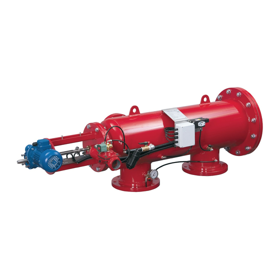
Page 9: Description Of Filter Operation
The SAF-6000 is a sophisticated yet easy-to-operate automatic filter, with a self-cleaning mechanism driven by an electric motor. The SAF-6000 is designed to work with various types of screens in filtration degrees from 10 to 500 micron, and is available in 6", 8" and 10"... - Page 10 System Operation modes: The filtration system may be found in one of the following modes: 1. Filtering mode: This is the normal operating status. The flush mode is idle and the power light on the control board is lit. 2. Flush mode: The motor and exhaust valve activate according to the previously described self-cleaning process. 3.
-
Page 11: Installation
Installation Design recommendations: 1. Often, flow increases and pressure drop dramatically during fill-up of a water system. In this case, a pressure-sustaining valve installed downstream of the filter will ensure the minimum required pressure for the filter and a controlled filling-up of the line. 2. - Page 12 Start-up and first operation Make sure all the electric wiring is correct, according to the enclosed drawings. Turn on control power and 24VAC but leave OL protector off. Verify that the limit switches are wired correctly by manually toggling them. Monitor the appropriate inputs according to the wiring diagram accompanying the control panel. Proceed to next step only after verifying correct wiring of all limit switches in the system.
-
Page 13: Maintenance
Maintenance General inspection Initiate a flush cycle by closing the 1/4" valve at the low pressure sensing port of the pressure differential switch for 5 seconds. Check that the exhaust valve opens, that the scanner moves properly, and when it reaches the limit switch - verify that the exhaust valve closes. Weekly maintenance: Check that the filter operates properly, following a general inspection. - Page 14 Cleaning the coarse screen: (See drawing on this page) Close the filter inlet valve. Release pressure from the filter by operating a flushing cycle. Remove the service lid (25) by disconnecting the bolts (26) from the nuts (28) Clean the coarse screen: To remove large particles, insert your hand into the coarse screen area.
-
Page 15: Troubleshooting
Troubleshooting Before beginning any troubleshooting, carefully read the safety instructions chapter of this document and make sure that all the workers at the filtration site are fully aware of and comply with these and any other local safety instructions. The filtration system may enter a malfunction mode in the following cases: Symptom Remarks and Actions Fault due to continuous signal from the... -
Page 16: Dismantling And Assembling The Filter Components
Dismantling and Assembling the Filter Components Prior to opening the filter perform a flush cycle by pressing the "TEST" push button. The Fine screen Dismantling: 1. Close the filter inlet and outlet valves and release the pressure. 2. Press the "TEST" push button and disconnect the power when the scanner is in the middle of its track (When the limit switch disc is half-way between the two limit switches). - Page 17 The suction scanner: Dismantling: 1. Begin the dismantling procedure as per 1-6 in the chapter "dismantling the fine screen". 2. Partially release the tightening nut (17 on page 24). 3. Pull out the drive shaft connecting pin (12) by first removing the split pin (13). 4.
- Page 18 The drive shaft housing and coarse screen: Dismantling: 1. Close the inlet and outlet valves of the filter and release pressure. 2. Disconnect power supply from the control board. 3. Remove the cover (34) from the drive shaft housing (5) by unscrewing the wing nuts. Pull out the plug from the solenoid coil, remove the limit switch sling (9 on page 24) from the drive shaft housing by unscrewing the bolts (14 on page 24).
-
Page 19: Parts Schedule - Saf-6000 Filter Section 1
Hex Bolt Partial Thread M16X60 Z.PLT C/ST Smooth Blind Flange 6" BSTD Coated Drive Shaft Key (SAF) Drive Unit SAF-6000 220/440VAC 3Ph 0.25KwX1400 RMI50 1/49 71 B5 Hex Bolt Full Thrd M8x40 Z.Plated c/st DIN933 Flat Washer M8 DIN125 Zinc Plated C/St... - Page 20 Description Manometer Valve 1/4" W/ Drain L-Connector 1/4"FX1/4"M Nickel Plated T Connector 1/4"X5/16"X5/16" Brass T-Connector 1/4" FxFxM (Brass) L-Connector 5/16"X1/8" Valve 3-Way 1/4" Pressure Gauge 16 Bar 1/4" Back Inlet Connector 5/16"x1/4" Insrtumentation Combined Bracket SAF Hex Bolt Full Thread M6x20 S/St304 DIN933 Flat Washer M6 DIN125 S/ST316 Spring Washer M6 DIN127 S/ST316 Hex Nut M6 S/ST316 DIN934...
-
Page 21: Parts Drawing Section 1
Parts Drawing Section 1 SAF 6000 910101-000107 07.2019 Page 21 of 28... -
Page 22: Parts Drawing Section
Parts Drawing Section 1 (Page 2) SAF 6000 910101-000107 07.2019 Page 22 of 28... -
Page 23: Parts Schedule Section 2
Parts Schedule Section 2 Description Drive Shaft Housing SAF-6000 PKPK-3002 Drive Bushing (SAF) Hex Bolt Full Thread M6x35 DIN933 S/St 304 Flat Washer M6 DIN125 S/ST316 Nylon Insert Lock Nut M6 S/ST304 DIN985 Drive Shaft (SAF-6000) Limit Switch Plate (SAF) HD... -
Page 24: Parts Drawing Section 2
Parts Drawing Section 2 SAF 6000 910101-000107 07.2019 Page 24 of 28... -
Page 25: Parts Schedule & Drawing Section 3 (Page 1) Suction Scanner- Sln Type
Description SLN Scanner Assembly SAF-6000 Machined Suction Scanner Shaft Connecting Pin (Shaft To Scanner) Plug Threaded M8 for SAF-6000 PRO Lower Bearing Insert SAF-6000 Spring Loaded Nozzle Cap SAF-6000 Scanner Nozzle Body SLN Sc.SAF-6000 Tightening Nut for SLN Scanner SAF-6000... -
Page 26: Parts Schedule & Drawing Section 3 (Page 2) Suction Scanner- Std. Type
Suction Scanner- Std. Type Description Scanner Assembly Improved SAF-6000 Machined Lower Bearing Insert SAF-6000 Suction Scanner Shaft Suction Scanner Nozzle (SAF-6000) Plug Threaded M8 for SAF-6000 PRO Connecting Pin (Shaft To Scanner) SAF 6000 910101-000107 07.2019 Page 26 of 28... -
Page 27: Amiad Limited Warranty
In no event shall Amiad be liable to the Buyer or any third party for any damages to property, or for any intangible or economic loss, including loss of profits, loss of customers or damage to reputation, for any damages, including indirect, special, consequential damages, or punitive damage arising out of or in connection with this Warranty, or arising out of or in connection with the product's performance or failure to perform, even if it has been advised of the possibility of such damages. - Page 28 Manufacturer Amiad Water Systems Ltd. D.N. Galil Elyon 1, 1233500, Israel. Tel: +972 4690 9500 | Fax: +972 48141159 | Email: info@amiad.com European Authorised Representative for CE Obelis s.a. Bd Général Wahis 53, 1030 Brussels, Belgium. Tel: +(32) 2732 5954 | Fax: +(32) 27326003 | Email: mail@obelis.net...
Need help?
Do you have a question about the SAF-6000 and is the answer not in the manual?
Questions and answers