
Related Manuals for amiad SAF-1500


Summary of Contents for amiad SAF-1500
- Page 1 AMIAD Water Systems SAF-1500 FILTER Serial number: Order number: Catalog number: Filtration degree: Tested by: Installation, Operation and Maintenance Instructions 910101-000102 / 07.2019...
-
Page 2: Saf-1500 Filter - User Manual
This document does not replace any certified drawing, procedure or information provided by Amiad in reference to a specific customer, site or project. Amiad assumes that all users understand risks involved within this file and/or its attached materials. This document is given in good faith and is not intended to impose any obligation to Amiad. -
Page 3: Table Of Contents
Section 2: Drive Shaft Housing ..............................22 PARTS SCHEDULE & DRAWING – Standard SAF-1500 Filter Section 3: Scanner ................. 23 PARTS SCHEDULE & DRAWING - Standard SAF-1500 Filter Section 3: SLN Scanner ..............24 AMIAD LIMITED WARRANTY ................................ 25 With any inquiry please quote Filter Serial Number, located on the filter housing. -
Page 4: Technical Specifications
TECHNICAL SPECIFICATIONS General Maximum flow rate 80 m 350 USgpm Consult manufacturer for optimum flow depending on filtration degree & water quality. Min. working pressure 1.5 bar 21 psi or lower if pressure is increased for flushing Max. working pressure 10 bar 150 psi 16 bar = 240 psi upon request... -
Page 5: Safety Instructions
➢ Always observe standard safety instructions and good engineering practices whilst working in the filter’s vicinity. ➢ Use the filter only for its intended use as designed by Amiad, any misuse of the filter may lead to undesired damage and may affect your warranty coverage. -
Page 6: Commissioning
➢ Commissioning the filter should be done by an authorized Amiad technician, do not attempt to commission the filter unaccompanied since this may lead to undesired damage and may affect your warranty coverage. -
Page 7: Maintenance
Maintenance Before any maintenance or non-regular operation please read the following: ➢ Servicing the filter should be done only by technicians authorized by Amiad. ➢ Disconnect the filter from the power supply and lock the Main Power Switch. ➢ Disconnect the compressed air supply, release the residual pressure and lock the Pneumatics Main Valve. -
Page 8: Dimensional And Recommended Installation Drawing
DIMENSIONAL AND RECOMMENDED INSTALLATION DRAWING Drawing No. 1: Modular configuration Key: Dimensions: mm (inches) 1. 3" SAF 1500 2. 3" inlet butterfly valve 3. 3" by-pass valve 4. 3" downstream valve 5. 3" non-return check valve * Minimum distance required for maintenance. - Page 9 DIMENSIONAL DRAWING – Standard SAF 1500 SAF - 1500 910101-000102 07.2109 Page 9 of 26...
-
Page 10: Description Of Filter Operation
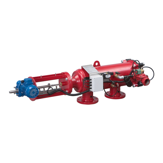
The SAF-1500 is a sophisticated yet easy-to-operate automatic filter, with a self-cleaning mechanism driven by an electric motor. The SAF-1500 is designed to work with various types of screens in filtration degrees from 500 to 10 micron, and is available in 2", 3" and 4" inlet/outlet diameter. - Page 11 The filtration system may enter a malfunction mode in the following cases: 1st. When there is a continuous signal from the pressure differential switch for a duration of more than the pre- set time. This means that the self-cleaning process is not successful. 2nd.
-
Page 12: Installation
INSTALLATION Design recommendations: 1. If flow increases and pressure drops dramatically for a long period of time during network filling-up, it is recommended that a pressure sustaining valve is installed downstream. The pressure sustaining valve will ensure a controlled filling-up of the line. - Page 13 Start-up and first operation 1. Make sure all the electric wiring is correct, according to the enclosed drawings. Switch the control & 24V circuit breakers and the motor protector to ON. The motor will start operating *. The suction scanner shaft should turn clockwise and move towards the filter housing until it reaches limit switch "A". If the motor rotates in the opposite direction, disconnect the electricity immediately and change the direction of the motor rotation by changing between two phases.
-
Page 14: Maintenance
MAINTENANCE General inspection In order to check the proper operation of the filter, close the low-pressure 1/4" valve to the pressure differential switch for a period of 5 seconds. This will initiate the self-cleaning cycle: Check that the exhaust valve opens, that the scanner moves forwards, and when it reaches the limit switch - verify that the exhaust valve closes. - Page 15 Maintenance prior to re-operation: 1. Connect the control board to the power supply. 2. Check proper operation of the filter. 3. Grease the drive shaft and the drive bushing. 4. If necessary, change the Sealing nut internal O-Ring. IMPORTANT!! THE DRIVE SHAFT MUST BE LUBRICATED WITH HEAVY-DUTY, WATER RESISTANT GREASE THAT WILL NOT OXIDIZE.
-
Page 16: Dismantling And Assembling The Filter Components
DISMANTLING AND ASSEMBLING THE FILTER COMPONENTS Prior to opening the filter perform a flush cycle by pressing the "TEST" push button. Dismantling the screens: 1. Close the filter inlet and outlet valves and release the pressure by operating a flushing cycle, Disconnect power supply from the control board. - Page 17 Dismantling the drive shaft housing: 1. Close the inlet valve to the filter, release the pressure and disconnect power supply from the control board. 2. Dismantle the suction scanner and screens as described previously. 3. Remove the limit switch sling (6 p.24) from the drive shaft housing by unscrewing the bolts. Carefully put the limit switch sling near the filter to avoid any damage to the electrical wires.
-
Page 18: Parts List - Standard Saf-1500
PARTS LIST – Standard SAF-1500 DESCRIPTION Qty. Housing 3" SAF-1500 Slotted Pin 10x30 DIN1481 O-Ring Seal P2-433 (Drive Unit Adaptor EBS H-SAF) NBR N/F Drive Shaft Assembly SAF-1500/3000 Bolt M16X60 Z.Plated Flat Washer M16 Z.Plated Hex Nut M16 Z.Plated Suction Scanner Assembly SAF-1500 Connecting Pin (SAF-1500,3000, 4500) Split Pin 1.6X12 DIN94 S/ST316... - Page 19 DESCRIPTION Qty. Ball Valve 3/4" M/F (BRASS) L-Connector 3/4" F/M Galvanized 3/4" BSPT AC BLACK SCREEN 200 M Raccord Nipple 1/4" for 3/4" Filter Raccord Nut 3/4" for 3/4" Filter O-Ring Seal P2-112 NBR Hydraulic Valve Pressure Check Point Connector 1/4"X1/4" Solenoid Valve Control Tube 5/16"...
-
Page 20: Parts Drawing - Standard Saf-1500 Section
PARTS DRAWING - Standard SAF-1500 Section 1: Page 1... - Page 21 PARTS DRAWING - Standard SAF-1500 Section 1: Page 2 SAF - 1500 07.2019 Page 21 of 26...
-
Page 22: Parts Schedule & Drawing - Standard Saf-1500 Filter
PARTS SCHEDULE & DRAWING – Standard SAF-1500 Filter Section 2: Drive Shaft Housing DESCRIPTION QTY. Drive Shaft Housing SAF-1500/3000 PKPK-3002 Drive Shaft (SAF-1500,3000,4500) Drive Bushing (SAF) Limit Switch Plate (SAF) HD EXT RETAINING RING 17MM S/ST304 DIN471 HD Limit Switch Sling (SAF) -
Page 23: Parts Schedule & Drawing - Standard Saf-1500 Filter Section 3: Scanner
PARTS SCHEDULE & DRAWING – Standard SAF-1500 Filter Section 3: Scanner DESCRIPTION QTY. SUCTION SCANNER SAF-1500 SS316L F/SCANNER DW SUCTION SCANNER SHAFT SAF-1500 SS316 DW PIN FOR SHAFT (SAF-1500) 35X5 S/ST PLUG 8MM SAF POM F/SCANNER NOZZLE SAF-1500 POM SCANNER SAF - 1500 07.2019... -
Page 24: Parts Schedule & Drawing - Standard Saf-1500 Filter Section 3: Sln Scanner
PARTS SCHEDULE & DRAWING - Standard SAF-1500 Filter Section 3: SLN Scanner DESCRIPTION QTY. SLN SUC Scan Assy IMPR SAF-1500 Machined Suction Scanner Shaft (SAF-1500) SLN Body SAF-3000/1500 Spring Loaded Nozzle Seal - SAF (Blue) SLN Tightening Nut SAF-4500/3000 SLN Cap SAF-3000/45000 SLN Spring Seat SAF-3000/4500 Spring Loaded Nozz. -
Page 25: Amiad Limited Warranty
In no event shall Amiad be liable to the Buyer or any third party for any damages to property, or for any intangible or economic loss, including loss of profits, loss of customers or damage to reputation, for any damages, including indirect, special, consequential damages, or punitive damage arising out of or in connection with this Warranty, or arising out of or in connection with the product's performance or failure to perform, even if it has been advised of the possibility of such damages. - Page 26 Amiad Water Systems Ltd. D.N. Galil Elyon 1, 1233500, Israel. Tel: +972 4690 9500 | Fax: +972 48141159 | Email: info@amiad.com Obelis s.a. Bd Général Wahis 53, 1030 Brussels, Belgium. Tel: +(32) 2732 5954 | Fax: +(32) 27326003 | Email: mail@obelis.net...
Need help?
Do you have a question about the SAF-1500 and is the answer not in the manual?
Questions and answers