
Subscribe to Our Youtube Channel
Related Manuals for amiad SAF-4500


Summary of Contents for amiad SAF-4500
-
Page 1: Amiad Water Systems
AMIAD Water Systems SAF-4500 FILTER Serial number: Order number: Catalog number: Filtration degree: Tested by: Installation, Operation and Maintenance Instructions Ref: 910101-000341/07.2019... -
Page 2: Saf-4500 Sln Filter User Manual
Amiad assumes that all users understand risks involved within this file and/or its attached materials. This document is given in good faith and is not intended to impose any obligation to Amiad. While every effort has been made to ensure the information in this manual is accurate and complete, we would appreciate if you can bring any errors or omissions to the knowledge of Amiad or consult Amiad experts or its authorized representatives if you have any questions. -
Page 3: Table Of Contents
DISMANTLING AND ASSEMBLING THE FILTER COMPONENTS ............16 PARTS SCHEDULE – SAF-4500 FILTER – Section 1 ................18 PARTS DRAWING – SAF-4500 FILTER – Section 1 page 2 ..............21 PARTS SCHEDULE AND DRAWING Section 2 – Drive Shaft Housing ..........22 PARTS SCHEDULE AND DRAWING - Section 3 - Scanner .............. -
Page 4: Technical Specifications
TECHNICAL SPECIFICATIONS General Maximum flow rate 250 m 1100 USgpm Consult manufacturer for optimum flow according to filtration degree and water quality Min. working pressure 1.5 bar 21 psi Max. working pressure 10 bar 150 psi 16 bar (240 psi) upon request Filter area 4500 cm 700 in... -
Page 5: Safety Instructions
➢ Always observe standard safety instructions and good engineering practices whilst working in the filter’s vicinity. ➢ Use the filter only for its intended use as designed by Amiad, any misuse of the filter may lead to undesired damage and may affect your warranty coverage. -
Page 6: Commissioning
Operation procedures exactly as described in this manual. ➢ Commissioning the filter should be done by an authorized Amiad technician, do not attempt to commission the filter unaccompanied since this may lead to undesired damage and may affect your warranty coverage. -
Page 7: Maintenance
Maintenance Before any maintenance or non-regular operation please read the following: ➢ Servicing the filter should be done only by technicians authorized by Amiad. ➢ Disconnect the filter from the power supply and lock the Main Power Switch. ➢ Disconnect the compressed air supply, release the residual pressure and lock the Pneumatics Main Valve. -
Page 8: Recommended Installation Drawing
RECOMMENDED INSTALLATION DRAWING SAF – 4500 910101-000341 / 07.2019 Page 8 of 26... -
Page 9: Description Of Filter Operation
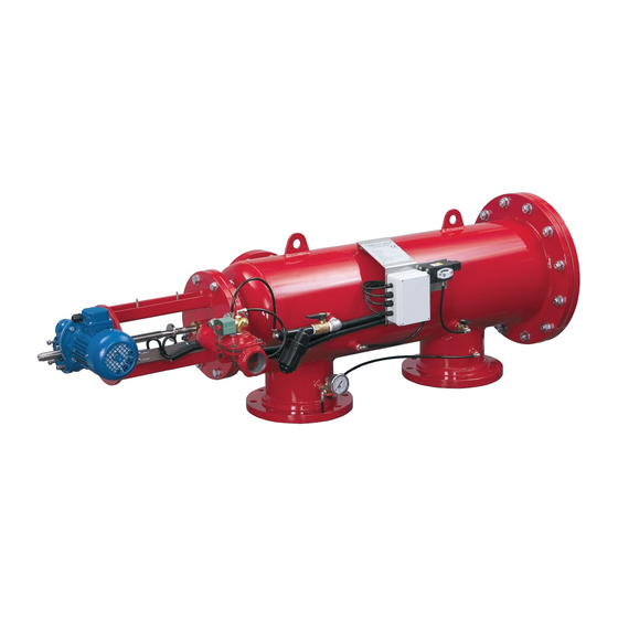
The SAF-4500 is a sophisticated yet easy-to-operate automatic filter, with a self-cleaning mechanism driven by an electric motor. The SAF-4500 is designed to work with various types of screens in filtration degrees from 10 to 500 micron, and is available in 4", 6" and 8" inlet/outlet diameter. - Page 10 Initiation of self-cleaning: The filter initiates the self-cleaning process under any one of the following conditions: 1. PD flush - The Pressure Differential Switch (PDS) closes a free potential contact signal when the pressure differential across the screen reaches the pre-set value (usually 0.5 bar =7 psi). The control board registers the signal and activates the flushing cycle.
-
Page 11: Installation
INSTALLATION Design recommendations: 1. Often, flow increases and pressure drop dramatically during fill-up of a water system. In this case, a pressure-sustaining valve installed downstream of the filter will ensure the minimum required pressure for the filter and a controlled filling-up of the line. - Page 12 Start-up and first operation 1. Make sure all the electric wiring is correct, according to the enclosed drawings. 2. Switch ON the control & 24V circuit breakers and the motor protector O.L. The motor will start operating *. 3. CHECK ROTATION: The suction scanner shaft should turn clockwise (CW) and move towards the filter housing until it reaches limit switch "A".
-
Page 13: Maintenance
MAINTENANCE General inspection Initiate a flush cycle by closing the 1/4" valve at the low pressure sensing port of the pressure differential switch for 5 seconds. Check that the exhaust valve opens, that the scanner moves properly, and when it reaches the limit switch - verify that the exhaust valve closes. - Page 14 Cleaning the coarse screen: 1. Close the filter inlet valve. 2. Release pressure from the filter by performing a flush cycle. 3. Remove the service lid (24) by disconnecting the bolts (26) from the nuts (28) 4. Clean the coarse screen: - To remove large particles insert your hand into the coarse screen area.
-
Page 15: Troubleshooting
TROUBLESHOOTING Before beginning any troubleshooting, carefully read the safety instructions in chapter 2 of this document and make sure that all the workers at the filtration site are fully aware of and comply with, these and any other local safety instructions. The filtration system may enter a malfunction mode in the following cases: Symptom Remarks and Actions... -
Page 16: Dismantling And Assembling The Filter Components
DISMANTLING AND ASSEMBLING THE FILTER COMPONENTS Prior to opening the filter perform a flush cycle by pressing the "TEST" push button. The Fine screen Dismantling: 1. Close the filter inlet and outlet valves and release the pressure. 2. Release the lid bolts (23) from their nuts and remove the lid (21). 3. - Page 17 The drive shaft housing and coarse screen: Dismantling: Close the inlet and outlet valves of the filter and release pressure. Disconnect power supply from the control board. Dismantle the suction scanner and fine screen as described previously. Pull out the plug from the solenoid coil (60). Remove the limit switch sling (6 on page 22) from the drive shaft housing by unscrewing the bolts (14 on page 22).
-
Page 18: Parts Schedule - Saf-4500 Filter - Section 1
PARTS SCHEDULE – STANDARD SAF-4500 FILTER – Section 1 Description SAF-4500 Housing Red Slotted Pin 10x30 DIN1481 SAF-4500 Flushing Chamber,Red Suction Scanner Bearing (SAF-4500) Locking Spring RING (SST316) O-Ring 60X4 Flushing Chamber NBR Coarse Screen SAF-4500 Parker Standard O-ring series P2-452... - Page 19 Flat Washer M5 DIN125 S/ST304 Hex Bolt Full Thread M6X20 S/ST304 DIN933 Flat Washer M6 DIN125 S/ST316 Hex Nut M6 S/ST316 DIN934 Spring Washer M6 DIN127 S/ST316 Aluminum Amiad Nameplate, CE, EN Rivet Blind 3x6 DIN7337 S/ST316 Pipe 5/16" PA Air Brake...
- Page 20 PARTS DRAWING – STANDARD SAF-4500 FILTER – Section 1 page 1 SAF – 4500 910101-000341 / 07.2019 Page 20 of 26...
-
Page 21: Parts Drawing - Saf-4500 Filter - Section
PARTS DRAWING – STANDARD SAF-4500 FILTER Section 1 page 2 SAF – 4500 910101-000341 / 07.2019 Page 21 of 26... -
Page 22: Parts Schedule And Drawing Section 2 - Drive Shaft Housing
PARTS SCHEDULE AND DRAWING STANDARD SAF 4500 Section 2: Drive Shaft Housing Description Drive Shaft House SAF-4500 Epoxy PKPK-3002 Drive Bushing (SAF) Drive Shaft (SAF-1500,3000,4500) Limit Switch Plate (SAF) HD Limit Switch Plate Locking Ring HD Limit Switch Sling (SAF) -
Page 23: Parts Schedule And Drawing - Section 3 - Scanner
PARTS SCHEDULE AND DRAWING STANDARD SAF 4500 Section 3 - Scanner Description NOZZLE SAF-4500 POM SCANNER SUC SCANNER SHAFT SAF-4500 PIN 5X45 S/ST316 PLUG 8MM SAF POM F/SCANNER SUCTION SCANNER SAF-4500 S/ST316 SAF – 4500 910101-000341 / 07.2019 Page 23 of 26... -
Page 24: Parts Schedule And Drawing - Section 3 - Sln Scanner
PARTS SCHEDULE AND DRAWING STANDARD SAF 4500 Section 3 SLN Scanner Description SLN Suction Scanner Improved SAF-4500 Machined Suction Scanner Shaft SAF-4500 PIN 5X45 S/ST316 PLUG 8MM SAF POM F/SCANNER SLN Cap SAF-3000/45000 O-RING Seal 2-016 NBR SLN Body SAF-3000/1500... -
Page 25: Amiad Limited Warranty
Buyer Complaint Form, the submission of the complaint or any questions please contact your service representative. Upon written demand by Amiad the Buyer shall return the Defective Product - or a sample thereof - to Amiad, at Amiad's cost. If the Buyer ships any such Defective Product, Amiad suggests the Buyer package it securely and insure it for value, as Amiad assumes no liability for any loss or damage occurring during shipment. - Page 26 Amiad Water Systems Ltd. D.N. Galil Elyon 1, 1233500, Israel. Tel: +972 4690 9500 | Fax: +972 48141159 | Email: info@amiad.com Obelis s.a. Bd Général Wahis 53, 1030 Brussels, Belgium. Tel: +(32) 2732 5954 | Fax: +(32) 27326003 | Email: mail@obelis.net...
Need help?
Do you have a question about the SAF-4500 and is the answer not in the manual?
Questions and answers