amiad Spin Klin Nova Installation, Operation & Maintenance Instructions Manual
Hide thumbs
Also See for Spin Klin Nova:

Subscribe to Our Youtube Channel
Related Manuals for amiad Spin Klin Nova


Summary of Contents for amiad Spin Klin Nova
- Page 1 Installation, Operation & Maintenance Instructions 3" Spin Klin™ 4" Spin Klin™ 2" Spin Klin™ Nova Plus Batery Nova Plus Batery Nova Batery External Source Backwash Systems 910101-001395/01.2025...
- Page 2 The confiden�al nature of and/or privilege in the file enclosed is not waived or lost as a result of a mistake or error in this file. If you received this file in error, please no�fy Amiad immediately at info@amiad.com.
-
Page 3: Table Of Contents
2" Spin Klin™ Nova Batery 3" Spin Klin™ Nova Plus Batery 4" Spin Klin™ Nova Plus Batery Spin Klin™ Nova Plus Command Filter Spin Klin Nova Mul�-Tool Installa�on & Ini�al Opera�on Generic Control scheme 2" SK Nova/3" SK Nova Plus Batery 4"... -
Page 4: Introduc�On
5. Always observe standard safety instruc�ons and good engineering prac�ces whilst working in the filter’s vicinity. 6. Use the filter only for its intended purpose as designed by Amiad Water Systems. Any misuse of the filter may lead to damage and may affect your warranty coverage. Consult with Amiad Water Systems prior to any non-regular use of this equipment. - Page 5 12. Ensure that any civil engineering work at the installa�on site such as construc�on, li�ing, welding, etc. is performed by qualified workers / technicians / contractors and in accordance with relevant local standards. 13. While using li�ing equipment, ensure that the filter or the li�ed part is atached securely and in a safe manner.
- Page 6 Mechanical 30. Use only appropriate standard tools when working on the filter. 31. Always open and close valves slowly and gradually. 32. Remove grease and oily material residues to avoid slipping. 33. Before disconnec�ng the filter from the water supply, electricity and pneuma�cs and before releasing the filter’s residual pressure DO NOT: a.
-
Page 7: Installa�On
Installa�on 34. Install the filter according to the detailed Installa�on Instruc�ons provided with the filter by the manufacturer and according to the descrip�on given in this manual. 35. Make sure to leave enough clearance to enable easy access for safe maintenance opera�ons. - Page 8 53. Empty the filter by opening the drainage valve. 54. Before opening the filter lock, check that there is no pressure in the filter. 55. In hot water systems wait un�l the filter components have cooled to a safe temperature. 56.
-
Page 9: Spin Klin Disc Technology
Spin Klin Disc Technology Spin Klin disc technology operates using thin, color-coded discs of a specific micron size. The discs are grooved on both sides, in opposite direc�ons, crea�ng a series of crossing points which form mul�ple par�cle traps The discs are stacked and compressed on a specially designed spine, producing a matrix of consecu�ve crossing points which trap the par�cles, thus crea�ng a depth filtra�on element. - Page 10 Filter Valves Modes Filtra�on Posi�on Inlet valve - Water flows from port [2] (main supply) to port [C] (filter connec�on). Port [1] (drain water outlet) is closed by the seal. Outlet valve – Filtered Water flows from port [C] (filter connec�on) to port [2] (Outlet manifold).
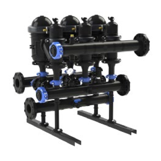
- Page 11 Spin Klin™ Nova Plus Battery Filtration and Backwash Process Filtration During the filtra�on stage, water flows through the inlet manifold and is distributed through the nova inlet valves into the Spin Klin filters. The water then passes through the filters' elements to the outlet manifold through the External Source flushing valves for consumer use.
- Page 13 2" Spin Klin™ Nova Batery Dimensional Drawings* *Drawings are for illustra�on only. There may be changes in the dimensions according to the design needs of Amiad. 2" Nova Plus Length Height Width Dry Weight Batery mm (inch) mm (inch) mm (inch)
-
Page 14: 2" Spin Klin™ Nova Batery
When the pressure downstream is over 6 bar / 87 psi during backwash, installing an orifice valve in the drain manifold is recommended in order to prevent damage to the SK spines. *Consult Amiad for op�mum flow depending on filtra�on degree and water quality. CONSTRUCTION MATERIALS... - Page 15 2" Spin Klin™ Nova Batery - Parts Schedule For more details, please visit Amiad Parts center: https://parts-center.amiad.com/...
- Page 16 2" Spin Klin™ Nova - Parts List ITEM NO PART NUMBER DESCRIPTION 19.1 710103-012291 ADAPTOR 2" NOVA GRV BLACK 19.2 700190-006487 NOVA SYSTEM CLAMP INDUSTRY ASSEMBLY 19.3 700190-006736 NOVA SINGLE BODY ASSEMBLY + 2"SK SEAT 19.4 700190-006735 ADAPTOR NOVA DRAIN 2"GRV NUT+SEALS ASSY INDUSTRY 19.5 700190-005739 NOVA VALVE ASSEMBLY...
- Page 17 3" SK Nova Plus Batery Dimensional Drawings* *Drawings are for illustra�on only. There may be changes in the dimensions according to the design needs of Amiad. 3" Nova Plus Length mm Height Width Dry Weight Batery (inch) mm (inch) mm (inch)
-
Page 18: 3" Spin Klin™ Nova Plus Batery
When the pressure downstream is over 6 bar / 87 psi during backwash, installing an orifice valve in the drain manifold is recommended in order to prevent damage to the SK spines. *Consult Amiad for op�mum flow depending on filtra�on degree and water quality. CONSTRUCTION MATERIALS... - Page 19 3" SK Nova Plus Batery - Parts Schedule For more details, please visit Amiad Parts center: https://parts-center.amiad.com/...
- Page 20 3" SK Nova Plus Batery - Parts List ITEM NO PART NUMBER DESCRIPTION 710103-012274 ADAPTOR 3" NOVA GRV BLACK 700190-006487 NOVA SYSTEM CLAMP INDUSTRY ASSEMBLY 700190-006048 NOVA SINGLE BODY ASSEMBLY 700190-006735 ADAPTOR NOVA DRAIN 2"GRV NUT+SEALS ASSY INDUSTRY 700190-005739 NOVA VALVE ASSEMBLY 700190-006594 NOVA VALVE ASSEMBLY SW (Sea Water) 700190-006535...
- Page 21 4" SK Nova Plus Batery Dimensional Drawings* *Drawings are for illustra�on only. There may be changes in the dimensions according to the design needs of Amiad. 4" Nova Plus Length Height Width Dry Weight Kg Batery mm (inch) mm (inch)
-
Page 22: 4" Spin Klin™ Nova Plus Batery
When the pressure downstream is over 6 bar / 87 psi during backwash, installing an orifice valve in the drain manifold is recommended in order to prevent damage to the SK spines. *Consult Amiad for op�mum flow depending on filtra�on degree and water quality. CONSTRUCTION MATERIALS... - Page 23 4" SK Nova Plus Batery - Parts Schedule For more details, please visit Amiad Parts center: https://parts center.amiad.com/ 1.5.1...
- Page 24 4" SK Nova Plus Batery – Parts List ITEM NO PART NUMBER DESCRIPTION QTY. 700190-006499 NOVA SINGLE IN-LINE FILTER INDUSTRY ASSEMBLY 710101-001821 NOVA DIVERTER INLINE CLOSED HOLES RPA BLACK 700190-006969 NOVA LONG DIVERTER CONNECTOR IN-LINE INDUSTRY ASSEMBLY W/O O-RING 700190-006048 NOVA SINGLE BODY ASSEMBLY 700190-006535 NOVA FLUSHING VALVE COVER ASSEMBLY INDUSTRY...
-
Page 25: Spin Klin™ Nova Plus Command Filter
Spin Klin™ Nova Plus Command Filter – Parts Schedule... -
Page 26: Spin Klin Nova Mul�-Tool
Spin Klin™ Nova Mul�-Tool A multifunction tool is provided with each Spin Klin™ Nova Filtration System. See below various usage options:... -
Page 27: Installa�On & Ini�Al Opera�On
Installa�on Prior to installation, flush the main line thoroughly to remove large objects that may damage the filter’s internal mechanism. 1. Connect the inlet and outlet ports and keep the service clearance from both sides. 2. Make sure that the inlet and outlet orienta�on is correct (shown by arrows on filter). 3. -
Page 28: Control Scheme
Control Scheme 2" SK Nova Battery/3" SK Nova Plus Battery – Air Command 2" SK Nova Battery/3" SK Nova Plus Battery - Water Command... -
Page 29: 4" Sk Nova Plus Batery
4" SK Nova Plus Battery - Air Command 4" SK Nova Plus Battery - Water Command... -
Page 30: Maintenance Procedures
Always observe standard safety instruc�ons and good engineering prac�ces whilst working in the filter’s vicinity. Use the filter only for its intended use as designed by Amiad, any misuse of the filter may lead to undesired damage and may affect your warranty coverage. Please consult with Amiad prior to any non-regular use of this equipment. - Page 31 7. Filter re-assembly. 8. Restart the filter as per the instructions given in this manual. Nova Plus Spare parts Kit for annual/periodic maintenance For more information and options about Amiad's maintenance kits please visit Amiad Parts center: https://parts-center.amiad.com/ Cat. No.
-
Page 32: Filter Disassembly / Assembly
Nova Filter Disassembly / Assembly Filter Disassembly/Assembly instructions video for maintenance is available via the link/QR Code: 1. Spin Klin™ Nova Flushing Valve and Disc Maintenance https://www.youtube.com/watch?v=GCLK-fLoprI 2. Spin Klin™ Nova command Filter Maintenance https://www.youtube.com/watch?v=lo1wuv8XhMk Note: Before any maintenance procedure, please depressurize and empty the filter. 1 .Close the inlet &... -
Page 33: Flushing Valve Disassembly
Flushing Valve Disassembly When using Air command system con�nue to step 3. 1. Open the command filter drain valve. 3. Unscrew the two bolts that join the system clamps using a 13mm (½") spanner and remove them. Note: For an overview of the loca�on of the Supply, Drain and Command tubes, please refer to the diagram located on 4. - Page 34 5. Remove the booster cylinder by pulling it 7. Push the piston valve forward and pull it back rapidly, un�l released. backwards. 6. For removing the valve assembly, please use both hands on the valve piston.
- Page 35 8. Visually inspect the valve for damage, paying close aten�on to the seals. Caution: Do not insert your finger into the marked area. The valve is spring-loaded. 9. Apply silicon grease (catalog number: 760190-000127) at the specific loca�ons as shown.
-
Page 36: Flushing Valve Assembly
Flushing Valve Assembly 1. Insert the piston valve by pushing the marked 4. Tighten the system clamps by using the two area. Please make sure that the orienta�on bolts with a 13mm (½") spanner. grooves are aligned and the valve sits properly. 2. - Page 37 5. When using Air command system, reconnect the air supply tube. When using an Hydraulic command system, connect the tubes of the water supply (S), water drainage (D) & command tube (C) to the booster cylinder according to the pictures below. 6.
-
Page 38: Main Cover & Filter Element Disassembly
Main Cover and Filter Element Disassembly Before any maintenance procedure, please depressurize and empty the filter (see "Maintenance Procedures"). Note: Cover disassembly procedure is identical for: 2" SK Nova Battery/ 3" SK Nova Plus Battery/ 4" SK Nova Plus Battery. 4. - Page 39 Perform the following steps to extract the discs for the cleaning procedure. 7. Open the buterfly nut by rota�ng it 11. The discs can be kept on the discs carrier or counterclockwise. seperately by pulling the carrier out. 8. Remove the buterfly nut. 12.
-
Page 40: Main Cover & Filter Element Assembly
Main Cover and Filter Element Assembly For disc reassembly, please follow these steps according to your designated system: Check that the correct quan�ty of discs is assembled on the spine: when the discs are pressed with two hands, the top disc should be leveled with the imprinted circle on the outside of the spine. 5. -
Page 41: Command Filter Disassembly
Command Filter (For Hydraulic command system only) Disassembly (both sides) Note: For an overview of the command filter cleaning procedure, please refer to the diagram located on the side of the command filter body. For each step you will find a designated number on the command filter body. 1. -
Page 42: Command Filter Assembly
Command Filter Assembly (both sides) 1. Insert the disc spine into the command filter body. 2. Close the command filter and �ghten the cover nuts. 3. Open the supply valve. Close the drain valve and ini�ate a manual backwash procedure in order to test the system. -
Page 43: Disc Cleaning Procedure
Disc Cleaning Procedure Maintenance - Discs To guarantee thorough cleaning the following steps should be taken: Attention: When carrying out any of the following seasonal maintenance, service, or cleaning the discs – after backwashing the system and after closing the water inlet, make sure that there is no pressure in the system! Cleaning recommendations for clogged filtration discs Water-formed deposits may cause clogging of the filter discs. - Page 44 Attention! While working with chemicals, protect yourself with the necessary safety equipment: 1. Safety glasses, gloves, protective clothing 2. Work in a well-ventilated area 3. Follow the manufacturer’s instructions. 4. Store and dispose of chemicals according to local law. Cleaning process (illustrations in the following page) Attention: Never open the filter before the pressure has been released.
- Page 45 Nova (2" Spine) Nova Plus (4" Spine) It is recommended to use a plastic bag. Use the disc carrier. Tie each set on a string. Use protective gloves to place the discs in a cleaning solution (see pages 46-49 for suitable options). Remove the discs from the cleaning solution and wash thoroughly under clean water.
- Page 46 Cleaning organic and biological deposits – with hydrogen peroxide (H Open the filter and remove dirty discs. Attention! Never open the filter before the pressure has been released. Arrange the discs loosely on the plastic rope Prepare a 5% peroxide solution (amount per disc set): Pour 21 liters of water into one of the large containers.
- Page 47 Cleaning manganese deposits Open the filter and remove the dirty discs. Arrange the discs loosely on the plastic rope. Prepare a 10% solu�on of citric acid: Pour 30 liters of water into one of the large containers. Carefully add 3 kg of solid citric acid into the water. S�r well un�l full dissolu�on of the acid. Soak the discs in the solu�on so that both sides are covered.
- Page 48 Remove the discs from both solutions, rinse them well with water and soak them in the second solution: put the two discs, which have been in the sodium hypochlorite solution, in the hydrochloric acid solution, and the other way around. Check the cleaning process: If one of the treatments removes all of the deposits, clean all of the discs following the same two-step procedure in the exact same order.
-
Page 49: Winteriza�On
Winteriza�on In order to prevent the filter battery from being damaged during water freezing (in cases where the system is not operating during winter) - drain all the water from the filter and the command filter and leave the drain valve open. - Page 50 Filter Disassembly for Water Draining When using Air command system, disconnect air supply tube and con�nue to step 3. 1. When using hydraulic command system, 3. Unscrew the two bolts that join the system open the command filter drain valve. clamps and remove them.
- Page 51 Assembly After Water Draining 1. Reassemble the booster cylinder on the Follow steps 4&5 only when using Hydraulic command flushing valve. system. 4. connect the tubes of the water supply (S), water drainage (D) & command tube (C) to the booster cylinder. 2.
-
Page 52: Troubleshoo�Ng
Troubleshoo�ng No Backwash Symptom Possible causes Required ac�ons Check the system flow rate. Check the Exceeded high flow rate drop down the inlet pressure. controller. No hydraulic command transfer Command filter is blocked. Manually clean the command filter. Check if there is compressed air pressure at the Open the air tap if there is one entrance to the solenoids No compressed air command... - Page 53 Con�nuous Flow to Drain Symptom Possible causes Required ac�ons Disconnect the 8mm command One or more of the solenoids do not release the tubes from the booster cylinder. command. Iden�fy the failure solenoid. Repair or replace as needed. Disconnect the 12mm drain tubes of Strong leakage through the the booster cylinder, check for drainpipe...
-
Page 54: Amiad Limited Warranty
Any altera�on, modifica�on, foreign atachment to or repair of the products, other than by Amiad or its authorized technical representa�ves. In no event shall Amiad be liable to the Buyer or any third party for any damages to property, or for any intangible or economic loss, including loss of profits, loss of customers or damage to reputa�on, for any damages, including indirect, special, consequen�al damages, or puni�ve... - Page 55 Manufacturer Amiad Water Systems Ltd. D.N. Galil Elyon 1, 1233500, Israel . Tel: +972 4690 9500 | Fax: +972 48141159 | Email: info@amiad.com European Authorised Representative for CE Obelis s.a. Bd Général Wahis 53, 1030 Brussels, Belgium. Tel: +(32) 2732 5954 | Fax: +(32) 27326003 | Email: mail@obelis.net...
Need help?
Do you have a question about the Spin Klin Nova and is the answer not in the manual?
Questions and answers