
Related Manuals for amiad SAF-3000


Summary of Contents for amiad SAF-3000
- Page 1 AMIAD Water Systems Ltd. SAF-3000 FILTER Serial number: Order number: Catalog number: Filtration degree: Tested by: Installation, Operation and Maintenance Instructions 910101-000112 / 07.2019 Original Instructions...
- Page 2 Amiad assumes that all users understand risks involved within this file and/or its attached materials. This document is given in good faith and is not intended to impose any obligation to Amiad. While every effort has been made to ensure the information in this manual is accurate and complete, we would appreciate if you can bring any errors or omissions to the knowledge of Amiad or consult Amiad experts or its authorized representatives if you have any questions.
-
Page 3: Table Of Contents
Parts Schedule and Drawing – SAF-3000 Section 2 ................21 Parts Schedule and Drawing – SAF-3000 Section 3 - Scanner ..............22 Parts Schedule and Drawing – SAF-3000 Section 4 - SLN Scanner ............23 Amiad Limited Warranty ................Error! Bookmark not defined. -
Page 4: Specifications
Specifications General Maximum flow rate 150 m 660 USgpm Consult manufacturer for optimum flow depending on filtration degree & water quality. Min. working pressure 1.5 bar 21 psi or lower if pressure is increased for flushing Max. working pressure 10 bar 150 psi Filter area 3,000 cm... -
Page 5: Safety Instructions
➢ Always observe standard safety instructions and good engineering practices whilst working in the filter’s vicinity. ➢ Use the filter only for its intended use as designed by Amiad, any misuse of the filter may lead to undesired damage and may affect your warranty coverage. -
Page 6: Commissioning
Operation procedures exactly as described in this manual. ➢ Commissioning the filter should be done by an authorized Amiad technician, do not attempt to commission the filter unaccompanied since this may lead to undesired damage and may affect your warranty coverage. -
Page 7: Maintenance
Maintenance Before any maintenance or non-regular operation please read the following: ➢ Servicing the filter should be done only by technicians authorized by Amiad. ➢ Disconnect the filter from the power supply and lock the Main Power Switch. ➢ Disconnect the compressed air supply, release the residual pressure and lock the Pneumatics Main Valve. -
Page 8: Dimensional Drawing
Dimensional Drawing Standard SAF 3000 SAF 3000 07.2019 Page 8 of 25... -
Page 9: Description Of Filter Operation
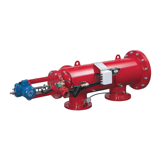
The SAF-3000 is a sophisticated yet easy-to-operate automatic filter, with a self-cleaning mechanism driven by an electric motor. The SAF-3000 is designed to work with various types of screens in filtration degrees from 10 to 500 micron, and is available in 3", 4"... - Page 10 Initiation of self-cleaning: The filter initiates the self-cleaning process under any one of the following conditions: 1. PD flush - The Pressure Differential Switch (PDS) closes a free potential contact signal when the pressure differential across the screen reaches the pre-set value (usually 0.5 bar =7 psi). The control board registers the signal and activates the flushing cycle. 2.
-
Page 11: Installation
Installation Design recommendations: Design recommendations: 1. Often, flow increases and pressure drop dramatically during fill-up of a water system. In this case, a pressure-sustaining valve installed downstream of the filter will ensure the minimum required pressure for the filter and a controlled filling-up of the line. 2. -
Page 12: Start-Up And First Operation
Start-up and first operation Make sure all the electric wiring is correct, according to the enclosed drawings. Turn on control power and 24VAC but leave OL protector off. Verify that the limit switches are wired correctly by manually toggling them. Monitor the appropriate inputs according to the wiring diagram accompanying the control panel. Proceed to next step only after verifying correct wiring of all limit switches in the system. -
Page 13: Maintenance
Maintenance General inspection Initiate a flush cycle by closing the 1/4" valve at the low pressure sensing port of the pressure differential switch for 5 seconds. Check that the exhaust valve opens, that the scanner moves properly, and when it reaches the limit switch - verify that the exhaust valve closes. -
Page 14: Cleaning The Coarse Screen
Cleaning the coarse screen: 1. Close the filter inlet valve. 2. Release pressure from the filter by performing a flush cycle. 3. Remove the filter lid (16), pull out the flushing chamber (14) with its seal (15). 4. Pull out the coarse screen (13) and clean it. 5. -
Page 15: Dismantling And Assembling The Filter Components
Dismantling and Assembling the Filter Components Prior to opening the filter perform a flush cycle by pressing the "TEST" push button. The screens Dismantling: 1. Close the filter inlet and outlet valves and release the pressure by performing a flush cycle. Power down the control board. 2. - Page 16 The drive shaft housing: Dismantling: 1. Close the filter’s inlet valve, release the pressure and disconnect power supply from the control board. 2. Dismantle the suction scanner and screens as described above. 3. Remove the limit switch sling (6 on page 21) from the drive shaft housing by unscrewing the bolts (17 on page 21). Carefully put the limit switch sling near the filter to avoid damaging the electrical wires.
-
Page 17: Parts Schedule - Saf-3000 Section 1
Parts Schedule – Standard SAF-3000 Section 1 No. Description Qty. Housing SAF-3000 Slotted Pin 10x30 DIN1481 O-Ring Seal P2-433 (Drive Unit Adaptor EBS H-SAF) NBR N/F Hex Bolt Partial Thread M16X60 Zinc Plated C/ST Flat Washer M16 DIN125 Zinc Plated C/ST... -
Page 18: Parts Drawing #1
No. Description Qty. Flat Washer M6 DIN125S/ST316 Hex Bolt Full Thread M6X20 S/ST304 DIN933 Spring Washer M6 DIN127 S/ST316 Hex Nut M6 S/ST316 DIN934 Ball Valve 3/4" M/F (BRASS) L-Connector 3/4" F/M Galvanized Raccord Nipple 1/4" for 3/4" Filter O-Ring Seal P2-112 NBR Raccord Nut 3/4"... - Page 19 Parts Drawing – Standard SAF-3000 Section 1: Page 1 SAF 3000 07.2019 Page 19 of 25...
-
Page 20: Parts Drawing #1
Parts Drawing – Standard SAF-3000 Section 1: Page 2 SAF 3000 07.2019 Page 20 of 25... -
Page 21: Parts Schedule And Drawing - Saf-3000 Section 2
Parts Schedule and Drawing – Standard SAF-3000 Section 2 No. Description Qty. Drive Shaft Housing SAF-1500/3000 Ployester Drive Shaft (SAF-1500,3000,4500) Drive Bushing (SAF) Limit Switch Plate (SAF) HD EXT RETAINING RING 17MM S/ST304 DIN471 HD Limit Switch Sling (SAF) Limit Switch NC (EBS,SAF) FA 4131-2DN... -
Page 22: Parts Schedule And Drawing - Saf-3000 Section 3 - Scanner
Parts Schedule and Drawing – Standard SAF-3000 Section 3: Scanner DESCRIPTION QTY. Scan Assembly for SAF-3000 Injection Nozzels Without Shaft Molded Scanner Nossle - Part 1 Molded Scanner Nossle - Part 2 Phillips Pan Tap Screw PT4x20 S/ST316 Suction Scanner Shft SAF-3000... -
Page 23: Parts Schedule And Drawing - Saf-3000 Section 4 - Sln Scanner
Parts Schedule and Drawing – Standard SAF-3000 Section 4: SLN Scanner DESCRIPTION QTY. SLN Suction Scanner Machined Improved SAF-3000 SLN Spring Seat SAF-3000/4500 SLN Cap SAF-3000/4500 SLN Tightening Nut SAF-4500/3000 SLN Body SAF-3000/1500 SLN Seal 16mm O-Ring Seal 2-016 NBR... -
Page 24: Amiad Limited Warranty
In no event shall Amiad be liable to the Buyer or any third party for any damages to property, or for any intangible or economic loss, including loss of profits, loss of customers or damage to reputation, for any damages, including indirect, special, consequential damages, or punitive damage arising out of or in connection with this Warranty, or arising out of or in connection with the product's performance or failure to perform, even if it has been advised of the possibility of such damages. - Page 25 Amiad Water Systems Ltd. D.N. Galil Elyon 1, 1233500, Israel. Tel: +972 4690 9500 | Fax: +972 48141159 | Email: info@amiad.com Obelis s.a. Bd Général Wahis 53, 1030 Brussels, Belgium. Tel: +(32) 2732 5954 | Fax: +(32) 27326003 | Email: mail@obelis.net...
Need help?
Do you have a question about the SAF-3000 and is the answer not in the manual?
Questions and answers