Table of Contents

Subscribe to Our Youtube Channel
Related Manuals for amiad Filtomat MG-110P


Summary of Contents for amiad Filtomat MG-110P
- Page 1 AMIAD Water Systems Filtomat MG-110P Serial Number: Order Number: Catalog Number: Filtration Degree: Tested By: Installation, Operation and Maintenance Instructions 910101-000571 /07.2013 Filtomat orders and support...
- Page 2 Disclaimer: This document and the information enclosed within it contain restricted and/or privileged information that are intended only for usage by authorized Amiad technicians. If you are not a qualified Amiad technician you must not take nay action in reliance to this document, unless permitted by Amiad.
-
Page 3: Table Of Contents
www.irrigationglobal.com TABLE OF CONTENTS Technical specifications ......................4 Dimensional drawing ........................5 Safety instructions ........................6 Introduction ..........................9 Installation ..........................12 Servicing ............................ 13 Maintenance ..........................15 The Flushing Controller ......................16 Parts schedule Section 1 ......................41 Parts drawing - Section 1 ......................42 Parts schedule Section 2 ...................... -
Page 4: Technical Specifications
www.irrigationglobal.com TECHNICAL SPECIFICATIONS General Maximum flow rate Consult manufacturer for optimum flow depending on MG-110P 350m /h; 1542USgpm filtration degree & water quality. Min. Working pressure 2.0bar; 30psi Or lower if pressure is increased for flushing Max. Working pressure 10bar; 150psi Filter area 13,600cm²;... -
Page 5: Dimensional Drawing
www.irrigationglobal.com DIMENSIONAL DRAWINGS MG110P 7.2013 Page 5 of 51... -
Page 6: Safety Instructions
Always observe standard safety instructions and good engineering practices whilst working in the filter’s vicinity. Use the filter only for its intended use as designed by Amiad, any misuse of the filter may lead to undesired damage and may affect your warranty coverage. - Page 7 Operation procedures exactly as described in this manual. Commissioning the filter should be done by an authorized Amiad technician, do not attempt to commission the filter unaccompanied since this may lead to undesired damage and may affect your warranty coverage.
- Page 8 Maintenance Before any maintenance or non-regular operation please read the following: Servicing the filter should be done only by technicians authorized by Amiad. Disconnect the filter from the power supply and lock the Main Power Switch. Disconnect the compressed air supply, release the residual pressure and lock the Pneumatics Main Valve.
-
Page 9: Introduction
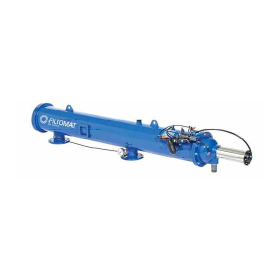
INTRODUCTION General Description The FILTOMAT MG110 is a sophisticated, yet easy-to-operate automatic filter, with a self-cleaning mechanism driven by a hydraulic turbine. It is designed to work with various types of screens in filtration degrees from 800 to 50 micron, and is available in 10" inlet/outlet diameter. - Page 10 Exhaust valve Nozzle Fine screen Rotor chamber Coarse screen Piston Dirt collector Rotor Drain Inlet Outlet Figure 3: Internal Components of the MG 110 Figure 4: Hydraulic Control Line Routing MG110P 7.2013 Page 10 of 51...
- Page 11 How the Flushing Controller Works The flushing controller is operated by 12 VDC. It receives a signal from the Differential Pressure Switch when the pressure differential reaches the preset value (0.5 Bar, 7 PSI). The flushing controller then sends a 12 VDC pulse to the Pulse Solenoid, which provides hydraulic pressure to the Hydraulic Relay which actuates the piston.
-
Page 12: Installation
INSTALLATION Design Recommendations The inlet and outlet pipes must be the same or a larger diameter than the inlet and outlet diameters of the filter. The upstream pressure source should not drop below 30 psi (2 bar) during the rinse cycle. If this cannot be ensured, consult the manufacturer. -
Page 13: Servicing
FIRST-TIME OPERATION 1. Remove a plastic plug from one of the outlet holes on the top of the filter to bleed air from the filter. 2. Open the inlet valve. 3. Close the plastic plug when all the air is bled from the filter. 4. - Page 14 Replacing the Piston 1. Drain the filter. 2. Remove the eight nuts holding the piston and cylinder assembly, and remove the assembly. 3. Inspect the suction scanner to make sure it moves freely in its bearings and the end that mates with piston is not damaged. 4.
-
Page 15: Maintenance
Maintenance It is recommended to inspect the filter once a year, in the off season. Remove the filter as described above and inspect the screen and O-rings, clean as necessary, and lubricate with silicone grease before reassembling. In cases where clogging of the inlet screen occurs, experience with the local conditions will determine how often the screen should be checked as a routine. -
Page 16: The Flushing Controller
PROGRAMMING THE FLUSHING CONTROLLER Amiad’s Flushing-Controllers product line is a family of electronic devices capable of controlling the flushing process of various automatic-filter models. Currently this line consists of three products; one AC controller and two DC controllers. This document is the user-manual of the 6 solenoids DC Controller and it describes the configuration process and the operation procedures of the V7 controller version. -
Page 17: Controller Can Serve
Introduction & How to use this manual Amiad’s Flushing-Controllers product line is a family of electronic devices capable of controlling the flushing process of various automatic-filter models. Currently this line is consisting of three products; one AC controller and two DC controllers. - Page 18 2. Only a qualified technician may remove this lid and only when the controller is properly disconnected from its power source. 3. Servicing the unit can be done only by Amiad’s qualified technician. 4. Make sure that the filters controlled by the controller are disconnected from the water system whenever servicing the controller.
- Page 19 The controller's enclosure is made of Polycarbonate and is designed for outdoor use (IP 65). B. Flushing Methods This chapter lists and describes the sequence of operation of the major flushing methods possible to operate using Amiad Flushing Controller: 1. Controlling Amiad TAF Electronic filter:...
- Page 20 A battery of TAF filters: A battery of Amiad TAF filters consists of several TAF filters installed in parallel and serves the same water system. Each one of these filters has its own flushing controller but the actual DP sensor is connected only to the first filter of the battery.
- Page 21 A battery of automatic screen or gravel media filters consists of 2-6 filters installed in parallel and serves the same water system, where one Amiad Flushing Controller controls the system. This arrangement allows a sequential flushing process where only one filter flushes at a time and the filters are flushed one after the other.
- Page 22 A battery of screen or gravel media filters with a Main Valve: Starting the flushing cycle: The same as in “A single TAF filter” above. The flushing cycle: The Main Valve solenoid is switched on and closes the battery’s Main Valve. The controller counts down the “Delay Main Valve Close”...
- Page 23 C. The User Interface Panel Amiad’s Flushing Controller User Interface Panel consists of: Display screen - a 2 X 16 characters LCD display. (See picture on the front page of this manual.) Keyboard – a 5 keys keyboard divided into 4 directional Arrow keys and an Enter key.
- Page 24 Amiad's DC Filter Flushing Controller - User Interface Layout (Page #1) For manual flush DC CONTROLLER v7 Status:B.Flushin TimeBet.Flushing FlushTime: 00:20 Flu Til Fault: 3 Press <ENTER> 09/10/07 11:13 Time: 4:23:35 5:00:00 (D:H:M) Bet.Filt.: 00:10 Delay: 10 Enter Enter Enter...
- Page 25 Amiad's DC Filter Flushing Controller - User Interface Layout (Page #2) Continues from page #1 See Chapter: How to Enter numbers and parameters Main valve: *yes Select language Filter number: 4 DP Input: *yes Delay valve: *yes * English Disc filter: *no...
- Page 26 D. Entering Data When the controller is first installed it is necessary to enter and/or adjust its basic parameters. These parameters, entered to the controller’s nonvolatile memory through a Configuration Process, enable it to perform the suitable flushing method designed for the type of filters it serves. Once the controller is properly configured a Flushing Program has to be entered.
- Page 27 Main valve: *no Main valve: *no Main valve: *no Delay valve: █no Delay valve: █no Delay valve: █no Enter Enter Enter Main valve: *no Main valve: *no Main valve: *no Delay valve: *no Delay valve: *no Delay valve: *no Entering a Number: 1.
- Page 28 Example: Changing the Delay Parameter from 10 to 37: Press the Right Arrow Key to delete the “10” digits. Use the Up or the Down Arrow Key to select "3". Press the Left Arrow Key to push the “3” to the left. Select "7"...
- Page 29 The layout of the screens involved in the configuration process can be found on page 11 of this manual. The following table describes each one of the screens of the configuration process and it contains three columns. The first column shows the screen number as appears at the upper left corner of the screen drawing in the layout diagram on page 11 of this manual.
- Page 30 Inputs: INPUTS OUTPUTS ------00 Left digit - DP sensor status: 0= no DP signal 1= DP signal is present Right digit – Pause input status: 0=no Pause signal 1= Pause signal is present Outputs: The first 6 digits from the left show the status of the filters, the main valve and the delay valve outputs: 0= The output is switched off 1= The output is switched on...
- Page 31 Number Screen Description This screen defines the time between scheduled flushing cycles. The entry format is Days (0-99), Hours (0-23) and minutes (0-59). TimeBet.Flushing 5:00:00 (D:H:M) Upper line: Defines the flushing time (the duration of flushing) of one filter. The FlushTime: 00:20 entry format is Minutes (0-99) and Seconds (0-59).
- Page 32 G. Monitoring During the regular operation of the controller it is possible to: Monitor the current status of the controller Read information on past activities of the system Perform manual operation and intervene in the flushing process Read and monitor the voltage of the controllers battery The layout of the screens involved in the controller’s Monitoring can be found on page 10 of this manual.
- Page 33 H. Handling faults Amiad’s flushing controller can detect and respond to filter clogs. This is done by monitoring the status of the D.P. signal. The user can configure the controller’s response through the following two screens: Number Screen Description If by the end of a flushing cycle the D.P signal remains ON the controller...
- Page 34 Battery and power levels: In order to prolong the battery life the controller switches off the display screen of the unit once the keyboard is not used. In such case the operation of the unit continues as usual. Press any key to switch on the display screen. The required voltage level for regular operation is 4.7-12 Volts.
- Page 35 D.P. input of an external controller (slave). This pulse lasts 5 seconds and takes place after all the other outputs of the flushing process have been activated and de-activated. See “Chaining Amiad Controllers” drawing at the end of this chapter.
- Page 36 Installing and replacing the batteries: The controller is powered by four D batteries. The unit starts to operate automatically 10 seconds after inserting the batteries. Alternatively, an external 6-12V DC supply can be connected to the power connection terminal; (Labeled as 6- 12 VDC on the terminal board circuit board.) If an external power supply is connected while a set of batteries is installed, the batteries are served as a backup and are not in use as long as the external power supply is connected.
- Page 37 I/O Terminal Connections Drawing: MG110P 7.2013 Page 37 of 51...
- Page 38 Chaining Amiad Controllers: In order to operate a battery of screen or gravel media filters that include a larger number of filters than one Amiad’s Flushing Controller can handle, it is possible to chain few controllers for the job. The D.P. switch that reads the pressure drop across the battery is connected to the first controller of the chain (the Master). The SEQ (or End of Cycle) output of the master controller is connected to the D.P.
- Page 39 Valve is used for sampling the flushing water. Amiad’s Flushing Controller contains two parameters which allow the user to control a filtration system that requires a Delay Valve; these are the “Delay Valve Open” and the “Delay Valve Close” parameters...
- Page 40 Starting the flushing cycle: The same as in “A single TAF filter” above. The flushing cycle: Solenoid valve number 1 is switched on and the flushing of the first filter of the battery starts. The controller starts to counts down two parameters in parallel: The “Flushing Time” parameter (see screen number and the “Delay Valve Open”...
-
Page 41: Parts Schedule Section 1
PARTS SCHEDULE Section 1 CAT. No. Description Material 710105-002509 Housing MG110-P ISO16 (2x10⁸LP) POLY PKPK-5010 ST. 37-2 760104-000075 Stud Bolt Special1/2"UNCX50 Long 20/12 S/ST 303 760103-000077 Flat Washer M12 DIN125 Zinc Plated C/ST Z.PLATED C/ST 760102-000052 DIN934 Nut UNC Galvanize ANSI 1/2 Z.PLATED C/ST 700190-001670 Various... -
Page 42: Parts Drawing - Section 1
PARTS DRAWING #1 (Page 1) MG110P 7.2013 Page 42 of 51... - Page 43 PARTS DRAWING #1 (Page 2) MG110P 7.2013 Page 43 of 51...
-
Page 44: Parts Schedule Section 2
PARTS SCHEDULE Section 2 CAT. No. Description Material 710103-000819 Cover 8 Holes Blue M10X(X)(L) Cast Iron 710103-000901 Seat Valve Seal M106 (Cast-Iron Cover) Delrin 710103-000902 Ring Retaining Cover Seat Seal M106 770102-000156 O-Ring Seal (P2-351) 50+5 NBR 710103-000869 Rod Piston M1XX(L)(P) S/St316 S/ST 316 770102-000126 O-Ring Seal (P2-237) Nat... -
Page 45: Parts Drawing - Section 2
PARTS DRAWING #2 MG110P 7.2013 Page 45 of 51... -
Page 46: Parts Schedule - Section 3
PARTS SCHEDULE Section 3 CAT. No. Description Material 710103-000920 Body Dirt Collector S/St304 (6 Noz) S/ST 304 710103-001483 Shaft Dirt Collector M-X04L/8L(P) Brass Brass 710103-001490 Connector Brass Dirt Col/Shaft MX04L/16P Brass 710103-000800 Central Support Collector NYLON 30%GF 710103-000802 Upper Plug Collector NYLON 30%GF 760101-000688 Phillips Pan Tap Screw #8x3/8"... -
Page 47: Parts Drawing - Section 3
www.irrigationglobal.com PARTS DRAWING #3 MG110P 7.2013 Page 47 of 51... -
Page 48: Parts Schedule - Section 4
www.irrigationglobal.com PARTS SCHEDULE Section 4 CAT. No. Description Material 700190-001707 M100-6800B Molded Screen 130 Micron Various 770102-000217 O-Ring Seal674 Shore 55-60 710103-001369 Ring Spacer For Bearing Assembly S/ST316 S/ST 316 710103-001424 Bearing Upper F/Screen MX03L/16P S/St 316 S/ST 316 710101-000717 Handle Screen Type 2 Nylon 6 NYLON 760101-000706... -
Page 49: Parts Drawing - Section 4
www.irrigationglobal.com PARTS DRAWING #4 Filtomat self cleaning filters on-line orders MG110P 7.2013 Page 49 of 51... -
Page 50: Parts Schedule - Section 5
Description Material 710102-000301 Bracket Plate MG Electronic COMP. Various 720103-000308 Solenoid Latch Valve Body S982-2L Various 720101-000334 AMIAD 6V/DC-6 Controller EN/SP Various 760101-000510 Phillips Pan Machine Screw M4x15 S/ST304 S/ST 304 760103-000092 Flat Washer M4 DIN125 S/ST304 S/ST 304 760102-000083... -
Page 51: Parts Drawing - Section 5
www.irrigationglobal.com PARTS DRAWING #5 Filtomat filters on-line orders MG110P 7.2013 Page 51 of 51...
Need help?
Do you have a question about the Filtomat MG-110P and is the answer not in the manual?
Questions and answers