Table of Contents
Advertisement
Quick Links
Advertisement
Table of Contents

Related Manuals for Siko SA01


Summary of Contents for Siko SA01
- Page 1 User manual Inclinometer with Analog-RS232-Interface IK360L – SA01...
-
Page 2: Table Of Contents
IK360L - Voltage ......................17 IK360L – Current ......................18 6.1.2 IK360L - ANALOG OUTPUT GRAPHS ..................19 IK360L (1 ......................19 AXIS OLTAGE IK360L (1 ......................19 AXIS URRENT IK360L-SA01-RS232 Date: 25.01.2017 Page 2 of 19 Art.no. 89211 Mod. Status 10/17... -
Page 3: General Safety Advice
Please Note Electrical equipment should be serviced only by qualified personnel. No responsibility is assumed by SIKO for any consequences arising out of the use of this material. This document is not intended as an instruction manual for untrained persons. -
Page 4: Analog Interface
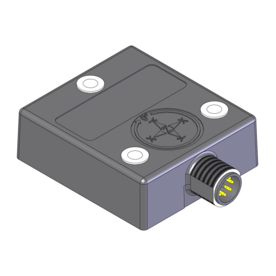
It is protected against polarity inversion and over voltage peak protection. In addition to that, the fully molded plastic housing provides an high resistance to shock/vibration and environmental protection of up to IP67. IK360L-SA01-RS232 Date: 25.01.2017 Page 4 of 19 Art.no. -
Page 5: Installation
"anywhere" makes it versatile. The IK360L inclinometer can be mounted in any number of fashions, depending on the situation. The mounting surface must be plane and free of dust and grease. It is absolutely IK360L-SA01-RS232 Date: 25.01.2017 Page 5 of 19 Art.no. -
Page 6: Measurement Axis
IK360L Inclinometers over long period of time. Measurement axis IK360L (1 axis) Measurement axis and mid angle position (factory setting ~ connector facing down) IK360L-SA01-RS232 Date: 25.01.2017 Page 6 of 19 Art.no. 89211 Mod. Status 10/17... -
Page 7: Ik360L Software Configuration
RS232. Teach-In Mode (Scaling) This is used for scaling of the analog output over a desired range, using RS232 or Analog inputs. IK360L-SA01-RS232 Date: 25.01.2017 Page 7 of 19 Art.no. 89211 Mod. Status 10/17... -
Page 8: Programmable Parameters
Preparation of IK360L 8- Wire open ended connection cable with M12 8-pin female connector RS232 Communication Cable D-Sub9 Female Connector only in Preset/Direction mode only in Teach-In mode IK360L-SA01-RS232 Date: 25.01.2017 Page 8 of 19 Art.no. 89211 Mod. Status 10/17... -
Page 9: Rs232 Communicarion - Pin Configuration
RS232 Communicarion – Pin Configuration 5.1.2 Description Receive data Transmit data Common Ground 5.1.3 Wiring & Connection 5.1.4 Connection Setup IK360L Analog -> M12 Connector -> RS232 Connector -> PC RS232 Port IK360L-SA01-RS232 Date: 25.01.2017 Page 9 of 19 Art.no. 89211 Mod. Status 10/17... -
Page 10: Software Communication Setup
Serial in Connection type and then type in the appropriate COM port in the Serial line column and the current Baud rate in the Speed dialog box. Then select, SSH -> Serial to setup the parameters for interface communication. IK360L-SA01-RS232 Date: 25.01.2017 Page 10 of 19 Art.no. -
Page 11: Boot-Up Message Representation
Serial Number IK360L Output – Programming Index The following table is of the character and its corresponding decimal/ hexadecimal equivalents to assist a user in the output programming. IK360L-SA01-RS232 Date: 25.01.2017 Page 11 of 19 Art.no. 89211 Mod. Status 10/17... - Page 12 In case of changing the baud rate, the new baud rate will be active direct after a <CR>, a "save" command is not required. Only sensors with version 1.86 software will have teach-in functionality. Refer to bootup message for version. Setorg is used for both setting the preset and scaling in both teach-in and Preset/direction modes. IK360L-SA01-RS232 Date: 25.01.2017 Page 12 of 19 Art.no.
-
Page 13: Preset/Direction And Teach-In Mode
Inverted according to the user’s requirement. The default setting is clockwise (IK360L). The analog input SET2 can be used for this function only if compl is set to "2". Default Factory settings IK360L-SA01-RS232 Date: 25.01.2017 Page 13 of 19 Art.no. 89211... -
Page 14: Teach-In Mode (Teach 1)
Preset of origin – 0° Reference for measurement Inversion of measurement direction Output scaling according to the set measurement range The IK360L has two configuration modes for the abov functionalities: IK360L-SA01-RS232 Date: 25.01.2017 Page 14 of 19 Art.no. 89211 Mod. Status 10/17... - Page 15 SET1 input SET2 input Voltage 100 ms Voltage 100 ms 5. Leave the teach-in mode by using the command "exit <CR>" via RS232 communication. Measurement range: Range Range IK360L-SA01-RS232 Date: 25.01.2017 Page 15 of 19 Art.no. 89211 Mod. Status 10/17...
-
Page 16: Preset
The scaling can be done also counter-clockwise. The output is scaled according to the direction of the sensor motion for the SET inputs. Upon scaling, the RS232 angular output sets preset automatically at SET1 position. IK360L-SA01-RS232 Date: 25.01.2017 Page 16 of 19 Art.no. -
Page 17: Analog Interface
Position Angle = (1.6662 V) / (0.02777 V per °) = 60° 2. U = 5.554 V Position Angle = (5.554 V) / (0.02777 V per °) = 200° IK360L-SA01-RS232 Date: 25.01.2017 Page 17 of 19 Art.no. 89211 Mod. Status 10/17... -
Page 18: Ik360L - Current
Position Angle = (8.31 mA - 4 mA) / (0.0444 mA per °) = 97.07° 2. I = 11.6 mA Position Angle = (11.6 mA - 4 mA) / (0.0444 mA per °) = 171.17° IK360L-SA01-RS232 Date: 25.01.2017 Page 18 of 19 Art.no. 89211... -
Page 19: Ik360L - Analog Output Graphs
IK360L - Analog Output Graphs IK360L (1 axis) Voltage Output circuit IK360L sensor Angle (°) IK360L (1 axis) Current Output circuit IK360L sensor Angle (°) IK360L-SA01-RS232 Date: 25.01.2017 Page 19 of 19 Art.no. 89211 Mod. Status 10/17...
Need help?
Do you have a question about the SA01 and is the answer not in the manual?
Questions and answers