Siko AP10S User Manual
Absolute / electronic position indicator with plug connector for magnetic sensor and io-link interface
Hide thumbs
Also See for AP10S:
- User manual (48 pages) ,
- Translation of the original installation instructions (44 pages)

Related Manuals for Siko AP10S


Summary of Contents for Siko AP10S
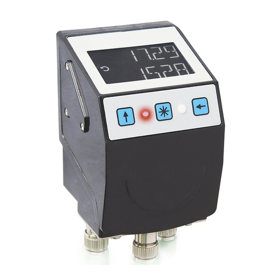
- Page 1 AP10S Absolute / Electronic Position Indicator with plug connector for magnetic sensor and interface User manual 110/20...
-
Page 2: Table Of Contents
Parameterization via interface ................18 Calibration ......................18 Sensor ........................19 Alignment travel ....................19 Additional functions ....................19 3.7.1 Device data ......................19 3.7.2 Restore factory settings ..................20 AP10S Date: 12.05.2020 Art. No. 90304 Mod. status 110/20 Page 2 of 44... - Page 3 IO-Link ........................35 Process data input / output ..................36 5.1.1 Process data in Absolute position operating mode ........... 37 Process data output (master device) .............. 37 5.1.1.1 AP10S Date: 12.05.2020 Art. No. 90304 Mod. status 110/20 Page 3 of 44...
- Page 4 5.1.2.2 Directory of objects ....................40 5.2.1 IO-Link specific objects..................40 SystemCommands ....................41 DeviceAccessLocks ....................42 EventCodes ......................42 ErrorCodes ......................42 Block diagram ......................43 AP10S Date: 12.05.2020 Art. No. 90304 Mod. status 110/20 Page 4 of 44...
-
Page 5: General Information
In addition, the position status of two two-color LEDs (green and red) is displayed. Device malfunctions or inadmissible operating conditions are displayed. Since both linear magnet sensors are used with the AP10S, a clockwise direction of rotation must be equated with a positive travel path. -
Page 6: Switching On The Operating Voltage
Switching on the operating voltage The AP10S will be initialized after switching on the supply voltage. A system and display test is executed during initialization, the LEDs are lighted consecutively and the parameters are loaded from the non-volatile memory into the RAM of the controller. -
Page 7: Extended Display Range
In the "Alphanumeric display" operating mode, the receipt of a target value is acknowledged by this action. Pressing the Configuration button starts the parameterization. See also chapter 3.3.1 Fig. AP10S Date: 12.05.2020 Art. No. 90304 Mod. status 110/20 Page 7 of 44... -
Page 8: Key Lock And Enable Time
A target window is formed to be able to define a tolerance range. Target window = TargetValue ± TargetWindow Example Position monitoring: TargetWindow = 5 TargetValue = 100 AP10S Date: 12.05.2020 Art. No. 90304 Mod. status 110/20 Page 8 of 44... - Page 9 The actual value is outside the programmed target window. The sensor must be moved in positive counting direction in order to reach the target. Table 2: LED display AP10S Date: 12.05.2020 Art. No. 90304 Mod. status 110/20 Page 9 of 44...
-
Page 10: Loop Positioning
This direction of approach can be defined. Since both linear magnet sensors are used with the AP10S, a clockwise direction of rotation must be equated with a positive travel path. -
Page 11: Statusword In Absolute Position Operating Mode
Table 3: ControlWord in Absolute Position operating mode 3.1.1.4 StatusWord in Absolute Position operating mode The Status Word shows the current status of the AP10S. The designation of the individual bits of the StatusWord as well as their meaning: Meaning... -
Page 12: Alpha-Numeric Display Operating Mode
LED1 green Display data acknowledged LED2 red Target value not acknowledged LED2 green Target value acknowledged Table 5: Status LED display in the alpha-numeric display operating mode AP10S Date: 12.05.2020 Art. No. 90304 Mod. status 110/20 Page 12 of 44... -
Page 13: Controlword: Alpha-Numeric Display
Activate LED Table 6: ControlWord alpha-numeric display operating mode 3.1.2.2 StatusWord: Alpha-numeric display The Status Word shows the current status of the AP10S. The designation of the individual bits of the StatusWord as well as their meaning: Meaning Value = 0... -
Page 14: Battery Buffering
For battery replacement it is mandatory to follow the instructions of the installation instructions. Replacement can also take place at the SIKO distribution partners or in the SIKO main plant. Behavior of the StatusWord: The charge status of the battery is signified in the StatusWord. -
Page 15: Manual Parameterization
For some parameters you can select values from a list. Direct value input is not possible there. Pressing the key, the value can be selected from the list. By pressing the key, the selection is confirmed. AP10S Date: 12.05.2020 Art. No. 90304 Mod. status 110/20 Page 15 of 44... -
Page 16: Overview Of The Operating Menu
>QUIT< Fig. 5: Menu selection 3.3.1.5 "Changeable parameters" menu The "Changeable parameters" menu is structured as follows: Description Display Page POSI Positioning VISUAL Visualization LEDS LED function AP10S Date: 12.05.2020 Art. No. 90304 Mod. status 110/20 Page 16 of 44... -
Page 17: Positioning
The following parameters can be set in the "LED function" menu: Description Display Chapter LED1GN Led1GreenMode 4.4.2 LED2GN Led2GreenMode 4.4.3 LED1RD Led1RedMode 4.4.4 LED2RD Led2RedMode 4.4.5 LED FL ActiveLedsFlashing 4.4.6 Table 11: "LED function" menu AP10S Date: 12.05.2020 Art. No. 90304 Mod. status 110/20 Page 17 of 44... -
Page 18: Device Options
With calibration, the CalibrationValue is adopted for calculation of the actual value. The following equation is applied in case (time) of calibration: Actual value = ActualValue = 0 + CalibrationValue AP10S Date: 12.05.2020 Art. No. 90304 Mod. status 110/20 Page 18 of 44... -
Page 19: Sensor
3.4). Alignment travel The AP10S is fully functional as delivered. To adjust the display to the connected sensor and to achieve optimum measuring accuracy, alignment travel must be carried out whenever a new/different sensor is connected to the AP10S. A safe sensor error detection is also only possible after a alignment travel has been carried out. -
Page 20: Restore Factory Settings
(see chapter 2.3). If calibration is required, this is indicated in the display as "CALIB". Independent of acknowledgment of the error status. AP10S Date: 12.05.2020 Art. No. 90304 Mod. status 110/20 Page 20 of 44... -
Page 21: Corrective Actions
All parameters stored in the EEPROM can be reset to factory default settings if necessary (see chapter 3.7.2). Chapter Starting with page Process data Positioning Visualization LEDs Device options AP10S Date: 12.05.2020 Art. No. 90304 Mod. status 110/20 Page 21 of 44... -
Page 22: Process Data
Sub-index Datastorage 4.1.2 StatusWord General characteristics EEPROM Unit Value range see chapter Default IO-Link Data type UnsignedInteger16 Access Index Sub-index Datastorage 4.1.3 TargetValue General characteristics EEPROM Unit AP10S Date: 12.05.2020 Art. No. 90304 Mod. status 110/20 Page 22 of 44... -
Page 23: Actualvalue
-2147483648 ... 2147483647 Default Display Value range -199999 ... 999999 4.1.5 DisplayData General characteristics EEPROM Unit Value range 6 character Default IO-Link Data type OctetString6 Access Index Sub-index Datastorage AP10S Date: 12.05.2020 Art. No. 90304 Mod. status 110/20 Page 23 of 44... -
Page 24: Targetvalueleft
IO-Link Data type UnsignedInteger32 Access Index Sub-index Datastorage Display chPARAM \ POSI \ RESOL Menu 4.2.2 DecimalPlaces General characteristics EEPROM Unit Value range 0 ... 4 Default AP10S Date: 12.05.2020 Art. No. 90304 Mod. status 110/20 Page 24 of 44... -
Page 25: Displaydivisor
Sub-index Datastorage Display chPARAM \ POSI \ DISDIV Menu Parameter selection Value Display Description Division by 1 Division by 10 Division by 100 1000 Division by 1000 AP10S Date: 12.05.2020 Art. No. 90304 Mod. status 110/20 Page 25 of 44... -
Page 26: Countingdirection
4.2.5 CalibrationValue General characteristics EEPROM Unit Value range -999999 ... 999999 Default IO-Link Data type SignedInteger32 Access Index Sub-index Datastorage Display chPARAM \ POSI \ CALVAL Menu AP10S Date: 12.05.2020 Art. No. 90304 Mod. status 110/20 Page 26 of 44... -
Page 27: Targetwindow
To compensate for the spindle play, the target value is always approached in the positive direction. To compensate for the spindle play, the target value is always approached in the negative direction. AP10S Date: 12.05.2020 Art. No. 90304 Mod. status 110/20 Page 27 of 44... -
Page 28: Looplength
0 ... 1 Default IO-Link Data type UnsignedInteger8/Bool Access Index Sub-index Datastorage Display chPARAM \ VISUAL \ DISPL Menu Parameter selection Value Display Description Orientation 0° Orientation 180° AP10S Date: 12.05.2020 Art. No. 90304 Mod. status 110/20 Page 28 of 44... -
Page 29: Leds
Index Sub-index Datastorage Display chPARAM \ LEDS \ LED1GN Menu Parameter selection Value Display Description Depending on the ControlBit Depending on the device status (see chapter 3.1) AP10S Date: 12.05.2020 Art. No. 90304 Mod. status 110/20 Page 29 of 44... -
Page 30: Led2Greenmode
Index Sub-index Datastorage Display chPARAM \ LEDS \ LED1Rd Menu Parameter selection Value Display Description Depending on the ControlBit Depending on the device status (see chapter 3.1) AP10S Date: 12.05.2020 Art. No. 90304 Mod. status 110/20 Page 30 of 44... -
Page 31: Led2Redmode
ActiveLedsFlashing General characteristics EEPROM Unit Value range 0 ... 1 Default IO-Link Data type Bool Access Index Sub-index Datastorage Display chPARAM \ LEDS \ LED FL Menu AP10S Date: 12.05.2020 Art. No. 90304 Mod. status 110/20 Page 31 of 44... -
Page 32: Device Options
\ OPTION \ SENSOR Menu Parameter selection Value Description MS500H GS04 4.5.2 KeyEnableTime General characteristics EEPROM Unit IO-Link Data type No access No access Index Sub-index Datastorage AP10S Date: 12.05.2020 Art. No. 90304 Mod. status 110/20 Page 32 of 44... -
Page 33: Keycalibration
General characteristics EEPROM Unit Value range 0 ... 1 Default IO-Link Data type UnsignedInteger8 / Bool Access Index Sub-index Datastorage Display chPARAM \ OPTION \ K INC Menu AP10S Date: 12.05.2020 Art. No. 90304 Mod. status 110/20 Page 33 of 44... -
Page 34: Operatingmode
PIN required to change parameters via buttons and display. General characteristics EEPROM Unit Value range 0 ... 999999 Default IO-Link Data type SignedInteger32 Access Index Sub-index Datastorage AP10S Date: 12.05.2020 Art. No. 90304 Mod. status 110/20 Page 34 of 44... -
Page 35: Loaddefault
IODD finder of the IO-Link Community. IO-Link Version V1.1 SIO-Mode Port Class A COM-Mode COM2 (38.4 kbaud) Min Cycle Time 9.2 ms Process Data In 8 Byte AP10S Date: 12.05.2020 Art. No. 90304 Mod. status 110/20 Page 35 of 44... -
Page 36: Process Data Input / Output
Table 19: Assignment of transfer sequence, sub-index and bit offset Byte 63 … 56 55 … 48 47 … 40 39 … 32 Fig. 6: Transmission sequence Fig. 7: Example representation in IO-Link master AP10S Date: 12.05.2020 Art. No. 90304 Mod. status 110/20 Page 36 of 44... -
Page 37: Process Data In Absolute Position Operating Mode
Bool see bc11 bc14_Led2Red Bool see bc11 bc15_LedBlinking Bool If true LEDs are blinking when on Table 21: Process data output in Absolute position operating mode AP10S Date: 12.05.2020 Art. No. 90304 Mod. status 110/20 Page 37 of 44... -
Page 38: Process Data Input (Device Master)
Octet Length operating mode) ActualValue TargetValue 4 … 7 Reserved TargetValueLeft 2 … 3 3 … 18 ControlWord StatusWord 0 … 1 Table 23: Process data definition AP10S Date: 12.05.2020 Art. No. 90304 Mod. status 110/20 Page 38 of 44... -
Page 39: Process Data Output (Master Device)
Process data input (device master) 5.1.2.2 Sub- Name Data Comment index offset length type PositionValue Signed- Absolute position value Integer Reserved bs00_Reserved Bool Used in AbsoluteMode bs01_Reserved Bool Used in AbsoluteMode AP10S Date: 12.05.2020 Art. No. 90304 Mod. status 110/20 Page 39 of 44... -
Page 40: Directory Of Objects
Record 2 Byte See IO-Link (0Ch) Interface Spec. ProfileCharacteristic Record 2 Byte See IO-Link (0Dh) Interface Spec. PDInputDescriptor Unsigned 3 Byte See IO-Link (0Eh) Integer16 Interface Spec. AP10S Date: 12.05.2020 Art. No. 90304 Mod. status 110/20 Page 40 of 44... -
Page 41: Systemcommands
Type Length Access Default Comment (hex) PDOutputDescriptor Unsigned 3 Byte See IO-Link (0Fh) Integer16 Interface Spec. VendorName String 9 Byte SIKO GmbH (10h) VendorText String 19 Byte www.siko- (11h) global.com ProduktName String 6 Byte _AP10S_ (12h) ProduktID String 1 Byte... -
Page 42: Deviceaccesslocks
Parameter value above limit Parameter value below limit Parameter length overrun Parameter length underrun Function not available Function temporarily not available Invalid parameter set Inconsistent parameter set AP10S Date: 12.05.2020 Art. No. 90304 Mod. status 110/20 Page 42 of 44... -
Page 43: Block Diagram
Table 30: Error codes Block diagram IO-Link master IO-Link interface reverse IO-Link master Power Position polarity pack indicator protection External Encoder magnetic sensor Battery Fig. 8: Block diagram AP10S Date: 12.05.2020 Art. No. 90304 Mod. status 110/20 Page 43 of 44... - Page 44 SIKO GmbH Weihermattenweg 2 79256 Buchenbach Phone + 49 7661 394-0 + 49 7661 394-388 E-Mail info@siko-global.com Internet www.siko-global.com Service support@siko-global.com AP10S Date: 12.05.2020 Art. No. 90304 Mod. status 110/20 Page 44 of 44...
Need help?
Do you have a question about the AP10S and is the answer not in the manual?
Questions and answers