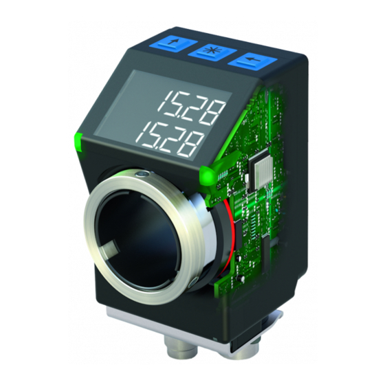
Siko AP05 User Manual
Absolute position indicator with interface
Hide thumbs
Also See for AP05:
- Installation instructions manual (40 pages) ,
- Translation of the original installation instructions (44 pages)
Table of Contents
Advertisement
Quick Links
Advertisement
Table of Contents

Subscribe to Our Youtube Channel
Related Manuals for Siko AP05


Summary of Contents for Siko AP05
- Page 1 AP05 Absolute Position Indicator with interface User manual 108/22...
-
Page 2: Table Of Contents
3.3.1.9 Device options ....................18 3.3.2 Parameterization via interface ................18 Calibration ......................18 Additional functions ....................19 3.5.1 Device information ....................19 3.5.2 Diagnosis ......................19 AP05 Date: 22.08.2022 Art. No. 90885 Mod. status 108/22 Page 2 of 50... - Page 3 3.6.2.1 Error memory ....................22 3.6.2.2 Error counter ....................23 3.6.3 Corrective actions ....................23 Adjustment run (already carried out at the factory for AP05) ........23 Parameter ....................... 24 Process data ......................24 4.1.1 ControlWord ....................... 24 4.1.2 StatusWord ......................24 4.1.3...
- Page 4 5.1.2.2 Directory of objects ....................46 5.2.1 IO-Link specific objects..................46 SystemCommands ....................47 DeviceAccessLocks ....................47 EventCodes ......................47 ErrorCodes ......................48 Block diagram ......................49 AP05 Date: 22.08.2022 Art. No. 90885 Mod. status 108/22 Page 4 of 50...
-
Page 5: General Information
• IODD file (IO-Link Device Description); with the help of this file, the connection and configuration with an IO-Link master is possible by means of commercially available IO- Link masters and their configurators. You can also download these documents at http://www.siko-global.com/p/ap05. 1.1.1 History Mod. -
Page 6: Switching On The Operating Voltage
Switching on the operating voltage The AP05 will be initialized after switching on the supply voltage. A system and display test is executed during initialization, the LEDs are lighted consecutively and the parameters are loaded from the non-volatile memory into the RAM of the controller. -
Page 7: Extended Display Range
COM LED state Description green Operating voltage OK green, Operating voltage OK blinks 90:10 IO-Link SDCI communication active Operating voltage too low Table 1: COM LED state AP05 Date: 22.08.2022 Art. No. 90885 Mod. status 108/22 Page 7 of 50... -
Page 8: Control Keys
The target value must be set to valid in the ControlWord (bc09_TargetValueActive). 3.1.1.1 Positioning Target window: A target window is formed to be able to define a tolerance range. AP05 Date: 22.08.2022 Art. No. 90885 Mod. status 108/22 Page 8 of 50... - Page 9 LED2 red The actual value is outside the programmed target window. The axis must be rotated clockwise to reach the target window. Table 3: LED display AP05 Date: 22.08.2022 Art. No. 90885 Mod. status 108/22 Page 9 of 50...
-
Page 10: Loop Positioning
The designation of the individual bits of the ControlWord as well as their meaning: Meaning Value = 0 Value = 1 bc00_CalibrationExecute Trigger calibration (edge controlled, positive) bc01_Reserved ever 0 bc02_Reserved ever 0 AP05 Date: 22.08.2022 Art. No. 90885 Mod. status 108/22 Page 10 of 50... -
Page 11: Statusword In Absolute Position Operating Mode
Table 4: ControlWord in Absolute Position operating mode 3.1.1.4 StatusWord in Absolute Position operating mode The Status Word shows the current status of the AP05. The designation of the individual bits of the StatusWord as well as their meaning: Meaning... -
Page 12: Alpha-Numeric Display Operating Mode
LED1 green Display data acknowledged. LED2 red Target value not acknowledged. LED2 green Target value acknowledged. Table 6: Status LED display in the alpha-numeric display operating mode AP05 Date: 22.08.2022 Art. No. 90885 Mod. status 108/22 Page 12 of 50... -
Page 13: Controlword: Alpha-Numeric Display
Activate LED Table 7: ControlWord alpha-numeric display operating mode 3.1.2.2 StatusWord: Alpha-numeric display The Status Word shows the current status of the AP05. The designation of the individual bits of the StatusWord as well as their meaning: Meaning Value= 0... -
Page 14: Battery Buffering
For battery replacement it is mandatory to follow the instructions of the installation instructions. Replacement can also take place at the SIKO distribution partners or in the SIKO main plant. Behavior of the StatusWord: The charge status of the battery is signified in the StatusWord. -
Page 15: Manual Parameterization
For some parameters you can select values from a list. Direct value input is not possible there. Pressing the key, the value can be selected from the list. By pressing the key, the selection is confirmed. AP05 Date: 22.08.2022 Art. No. 90885 Mod. status 108/22 Page 15 of 50... -
Page 16: Overview Of The Operating Menu
KeyEnableTime expired? PIN entry required Changeable parameter chPAr "Changeable PIN correct? parameters" menu Read-only device data Device information Diagnosis Diagnosis DIAGn Quit qu1t Fig. 5: Menu selection AP05 Date: 22.08.2022 Art. No. 90885 Mod. status 108/22 Page 16 of 50... -
Page 17: Changeable Parameters" Menu
OOP Table 10: "Positioning" menu 3.3.1.7 Visualization The following parameters can be set in the "Visualization" menu: Description Display Chapter DisplayOrientation 4.3.1 DIP Table 11: "Visualization" menu AP05 Date: 22.08.2022 Art. No. 90885 Mod. status 108/22 Page 17 of 50... -
Page 18: Led Function
ControlWord see chapter 5.1.1.1). During calibration using the control buttons, a countdown of 5 seconds is started and displayed. Calibration is completed after the countdown. AP05 Date: 22.08.2022 Art. No. 90885 Mod. status 108/22 Page 18 of 50... -
Page 19: Additional Functions
Reading the error memories Two different error histories can be output here. The "AP05" list contains errors found by the device such as "Low battery voltage" or "Velocity exceeded". With errors occurring, the error number and overall quantity are output on the upper line. The type of error appears in the lower line, with error number 1 containing the latest error. -
Page 20: Presentation
Table 16: Access to factory settings 3.5.4 Operation hours counter Various operating hours counters are in operation in the AP05. 3.5.4.1 General operating hours counter Detects the time during which the device is sufficiently supplied via the connection line and is therefore in operation. -
Page 21: Customer-Specific Operating Hours Counter
This warning is displayed with a blinking battery symbol. Warning messages are output via the interface via an IO-Link event and the StatusWord (see chapter 3.5.1, chapter 5.1.1.2 and chapter 5.5). AP05 Date: 22.08.2022 Art. No. 90885 Mod. status 108/22... -
Page 22: Errors
Sensor error, magnetic field faulty n Sensor error, reading head faulty non Sensor error, SIN COS monitoring nr Sensor error, internal error nIC Data memory faulty tor AP05 Date: 22.08.2022 Art. No. 90885 Mod. status 108/22 Page 22 of 50... -
Page 23: Error Counter
The value changes in the positive direction up to "103" in the lower line. If this value is exceeded in the end, the adjustment process has been completed. The AP05 is back in normal operation and shows the corresponding display. If values above "103" are displayed during the adjustment, the travel speed must be reduced during the adjustment. -
Page 24: Parameter
EEPROM Unit Value range See chapter Default IO-Link Data type UnsignedInteger16 Access Index Sub-index Data Storage 4.1.2 StatusWord General characteristics EEPROM Unit Value range See chapter Default AP05 Date: 22.08.2022 Art. No. 90885 Mod. status 108/22 Page 24 of 50... -
Page 25: Targetvalue
4.1.4 ActualValue General characteristics EEPROM Unit IO-Link Data type SignedInteger32 Access Index Sub-index Data Storage Value range -2147483648 ... 2147483647 Default Display Value range -19999 ... 99999 AP05 Date: 22.08.2022 Art. No. 90885 Mod. status 108/22 Page 25 of 50... -
Page 26: Displaydata
TargetValueLeft General characteristics EEPROM Unit Value range 2 characters Default IO-Link Data type OctetString2 Access Index Sub-index Data Storage Positioning 4.2.1 Resolution General characteristics EEPROM Unit Default AP05 Date: 22.08.2022 Art. No. 90885 Mod. status 108/22 Page 26 of 50... -
Page 27: Decimalplaces
\ POI \ DP Parameter selection Value Display Description 1 decimal place .1 2 decimal places .1 3 decimal places .1 4 decimal places .1 AP05 Date: 22.08.2022 Art. No. 90885 Mod. status 108/22 Page 27 of 50... -
Page 28: Displaydivisor
General characteristics EEPROM Unit Value range 0 ... 1 Default IO-Link Data type UnsignedInteger8 / Bool Access Index Sub-index Data Storage Display Menu chPAr \ POI \ CntDI AP05 Date: 22.08.2022 Art. No. 90885 Mod. status 108/22 Page 28 of 50... -
Page 29: Calibrationvalue
General characteristics EEPROM Unit User units Value range 0 ... 9999 Default IO-Link Data type UnsignedInteger16 Access Index Sub-index Data Storage Display Menu chPAr \ POI \ r1 AP05 Date: 22.08.2022 Art. No. 90885 Mod. status 108/22 Page 29 of 50... -
Page 30: Looptype
LoopLength General characteristics EEPROM Unit Value range 0 ... 9999 Default IO-Link Data type UnsignedInteger16 Access Index Sub-index Data Storage Display Menu chPAr \ POI \ OOP AP05 Date: 22.08.2022 Art. No. 90885 Mod. status 108/22 Page 30 of 50... -
Page 31: Visualization
Orientation 180° 1 LEDs 4.4.1 LEDMode General characteristics EEPROM Unit Value range 0 ... see sub-indexes Default IO-Link Data type UnsignedInteger8 Access Index Sub-index Data Storage AP05 Date: 22.08.2022 Art. No. 90885 Mod. status 108/22 Page 31 of 50... -
Page 32: Led1Greenmode
Data Storage Display Menu chPAr \ D \ rn Parameter selection Value Display Description Depending on the ControlBit O Depending on the device status O (see chapter 3.1) AP05 Date: 22.08.2022 Art. No. 90885 Mod. status 108/22 Page 32 of 50... -
Page 33: Led1Redmode
Data Storage Display Menu chPAr \ D \ r Parameter selection Value Display Description Depending on the ControlBit O Depending on the device status O (see chapter 3.1) AP05 Date: 22.08.2022 Art. No. 90885 Mod. status 108/22 Page 33 of 50... -
Page 34: Activeledsflashing
General characteristics EEPROM Unit IO-Link Data type Access No access Index Sub-index Data Storage Display Menu chPAr \ OPIO \ Value range 1 ... 60 Default AP05 Date: 22.08.2022 Art. No. 90885 Mod. status 108/22 Page 34 of 50... -
Page 35: Keycalibration
Access Index Sub-index Data Storage Display Menu chPAr \ OPIO \ ICn Parameter selection Value Display Description Functions disabled via key O Functions enabled via key O AP05 Date: 22.08.2022 Art. No. 90885 Mod. status 108/22 Page 35 of 50... -
Page 36: Operatingmode
PIN required to change parameters via buttons and display. General characteristics EEPROM Unit Value range 0 ... 99999 Default IO-Link Data type UnsignedInteger32 Access Index Sub-index Data Storage Display Menu chPAr \ OPIO \ PI AP05 Date: 22.08.2022 Art. No. 90885 Mod. status 108/22 Page 36 of 50... -
Page 37: Loaddefault
Start adjustment 10101 Start Presentation mode 11100 Reset all parameters to factory settings 50000 Reset customer-specific operating hours counter Error counter General characteristics EEPROM Unit Value range Default AP05 Date: 22.08.2022 Art. No. 90885 Mod. status 108/22 Page 37 of 50... -
Page 38: Event Counter For The Error "Battery Dead
IO-Link Data type UnsignedInteger8 Access Index Sub-index Data Storage Parameter selection Value Description 0 … 255 Number of newly detected errors of this type that have occurred AP05 Date: 22.08.2022 Art. No. 90885 Mod. status 108/22 Page 38 of 50... -
Page 39: Event Counter For The Error "Sensor Error, Magnetic Field Faulty
Number of newly detected errors of this type that have occurred 4.6.5 Event counter for the error "Sensor error, SIN COS Monitoring" General characteristics EEPROM Unit Value range 0 ... 255 Default AP05 Date: 22.08.2022 Art. No. 90885 Mod. status 108/22 Page 39 of 50... -
Page 40: Event Counter For The Error "Sensor Error, Internal Error3
Event counter for the error "Sensor error, internal error4" General characteristics EEPROM Unit Value range 0 ... 255 Default IO-Link Data type UnsignedInteger8 Access Index Sub-index Data Storage AP05 Date: 22.08.2022 Art. No. 90885 Mod. status 108/22 Page 40 of 50... -
Page 41: Io-Link
Table 21: Assignment of transfer sequence, sub-index and bit offset Byte 63 … 56 55 … 48 47 … 40 39 … 32 Fig. 6: Transmission sequence AP05 Date: 22.08.2022 Art. No. 90885 Mod. status 108/22 Page 41 of 50... -
Page 42: Process Data In Absolute Position Operating Mode
Used in DisplayMode bc00_CalibrationExecute Bool If true calibration becomes executed bc01_Reserved Bool bc02_Reserved Bool Used in DisplayMode bc03_DisplayRange Bool If true display range is extended bc04_GuardingBit Bool Communication guarding AP05 Date: 22.08.2022 Art. No. 90885 Mod. status 108/22 Page 42 of 50... -
Page 43: Process Data Input (Device Master)
Bool True if error occurred bs08_Reserved Bool Used in DisplayMode bs09_IncMeasurement Bool True if incremental measurement is active bs10_TargetValueState Bool True if target value is active AP05 Date: 22.08.2022 Art. No. 90885 Mod. status 108/22 Page 43 of 50... -
Page 44: Process Data In Alphanumeric Display Operating Mode
Bool If true the actual error is acknowledged bc06_TargetValueAckMode Bool If true TargetValue becomes acknowledged bc07_TargetValueTypeSelect 55 Bool Format of TargetValue bc08_DisplayDataTypeSelect 56 Bool Format of DisplayData AP05 Date: 22.08.2022 Art. No. 90885 Mod. status 108/22 Page 44 of 50... -
Page 45: Process Data Input (Device Master)
True if battery state is critical or low bs12_SpeedError Bool True if speed limit is violated bs13_KeyConfiguration Bool True if key is actuated bs14_KeyCalibration Bool True if key is actuated AP05 Date: 22.08.2022 Art. No. 90885 Mod. status 108/22 Page 45 of 50... -
Page 46: Directory Of Objects
3 Byte See IO-Link (0Eh) Integer16 Interface Spec. PDOutputDescriptor Unsigned 3 Byte See IO-Link (0Fh) Integer16 Interface Spec. VendorName String 9 Byte SIKO GmbH (10h) VendorText String 19 Byte www.siko- (11h) global.com ProduktName String 6 Byte _AP05_ (12h) ProduktID String... -
Page 47: Systemcommands
6146 (1802h) Battery empty Error Battery undervoltage (dead) 6158 (180Eh) Internal error 3 Error Sensor error, internal error3 6159 (180Fh) Internal error 4 Error Sensor error, internal error4 AP05 Date: 22.08.2022 Art. No. 90885 Mod. status 108/22 Page 47 of 50... -
Page 48: Errorcodes
Parameter length underrun Function not available Function temporarily not available Invalid parameter set Inconsistent parameter set Application not ready Vendor specific error code Table 32: Error codes AP05 Date: 22.08.2022 Art. No. 90885 Mod. status 108/22 Page 48 of 50... -
Page 49: Block Diagram
Block diagram Block diagram IO-Link master IO-Link interface IO-Link master reverse Power Position polarity pack indicator protection Axis Encoder Battery Fig. 8: Block diagram AP05 Date: 22.08.2022 Art. No. 90885 Mod. status 108/22 Page 49 of 50... - Page 50 SIKO GmbH Weihermattenweg 2 79256 Buchenbach Phone + 49 7661 394-0 + 49 7661 394-388 E-Mail info@siko-global.com Internet www.siko-global.com Service support@siko-global.com AP05 Date: 22.08.2022 Art. No. 90885 Mod. status 108/22 Page 50 of 50...
Need help?
Do you have a question about the AP05 and is the answer not in the manual?
Questions and answers