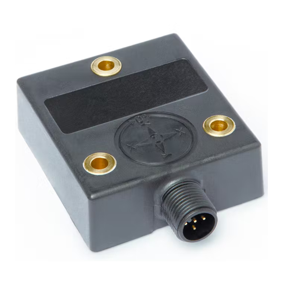
Siko IK360L User Manual
Inclinometer with analog-interface
Hide thumbs
Also See for IK360L:
- User information (8 pages) ,
- Translation of the original installation instructions (28 pages) ,
- User manual (19 pages)
Table of Contents
Advertisement
Quick Links
Advertisement
Table of Contents

Summary of Contents for Siko IK360L
- Page 1 User manual Inclinometer with Analog-Interface IK360L...
-
Page 2: Table Of Contents
Analog Inputs (SET1) ......................7 ANALOG INTERFACE ........................7 ..........................7 UTPUT YPES 4.1.1 IK360L - Voltage ........................ 7 IK360L – Current ....................... 8 4.1.2 IK360L - ANALOG OUTPUT GRAPHS ..................9 IK360L (1 ......................9 AXIS OLTAGE IK360L (1 ......................10 AXIS URRENT... -
Page 3: General Safety Advice
Please Note Electrical equipment should be serviced only by qualified personnel. No responsibility is assumed by SIKO for any consequences arising out of the use of this material. This document is not intended as an instruction manual for untrained persons. -
Page 4: Analog Interface
PLCs. An analog signal is a continuous signal which is analogous i. e. comparable to another time varying signal. In our case the variation of current or voltage signal from IK360L is analogous to the variation of measured position. -
Page 5: Installation
Installation Pin assignment The inclinometer is connected via a 8 pin round M12 connector (Standard M12, male connector on IK360L, female connector at connection cable). Description for IK360L (1 axis) Description für IK360L (2 axis) 10-30 V DC 10-30 V DC... -
Page 6: Mounting Instructions
Mounting instructions IK360L is a pre-calibrated device, which can be put into immediate operation, upon simple and easy installation with a three point mount and setting of preset. Its compact design and installation "anywhere" makes it versatile. The IK360L inclinometer can be mounted in any number of fashions, depending on the situation. -
Page 7: Analog Inputs (Set1)
IK360L (2 axis) 3.4.1 Analog Inputs (SET1) The IK360L has ab analog input, SET1 which can be used to configure in the IK360L. To trigger/activate these functionalities: The user must apply a positive voltage (5 V – 30 V, R >... -
Page 8: Ik360L - Current
IK360L – Current 4.1.2 Connect the corresponding (current analog output Pin 5) open end of the connection cable to the measurement system. IK360L output current, I can be directly measured or indirectly ≤270 Ω). measured as voltage, using a shunt resistor (Note: R... -
Page 9: Ik360L - Analog Output Graphs
Calculation of angle from IK360L (1 axis) current: Position angle (in °) = (I - 4 mA) / (0.0444 mA per °) For example: 1. I = 8.31 mA Position Angle = (8.31 mA - 4 mA) / (0.0444 mA per °) = 97.07°... -
Page 10: Ik360L (1 Axis ) Current
IK360L (1 axis) Current Output circuit IK360L sensor Angle (°) IK360L (2 axis) X-Axis Voltage Output Angle (°) X-axis IK360L (2 axis) Y-Axis Voltage Output Angle (°) Y-axis IK360L Date: 20.03.2017 Page 10 of 11 Art.no. 89210 Mod. Status 95/17... -
Page 11: Ik360L (2 Axis ) X-Axis Current Output
IK360L (2 axis) X-Axis Current Output Angle (°) X-axis IK360L (2 axis) Y-Axis Current Output Angle (°) Y-axis IK360L Date: 20.03.2017 Page 11 of 11 Art.no. 89210 Mod. Status 95/17...


Need help?
Do you have a question about the IK360L and is the answer not in the manual?
Questions and answers