Siko IK360L Translation Of The Original Installation Instructions
Inclinometer
Hide thumbs
Also See for IK360L:
- User manual (11 pages) ,
- User information (8 pages) ,
- User manual (19 pages)

Related Manuals for Siko IK360L


Summary of Contents for Siko IK360L
- Page 1 IK360L Inklinometer Deutsch Originalmontageanleitung Seite 2 Inclinometer English Translation of the Original Installation Instructions page 14 198/20...
-
Page 2: Table Of Contents
5.1 Analoger Spannungsausgang 5.2 Analoger Stromausgang 6 Transport, Lagerung, Wartung und Entsorgung 7 Zubehör Anschluss-Stecker 7.1 Gegenstecker M12 gerade inkl. Kabel 7.2 Gegenstecker M12 gerade 8 Technische Daten IK360L · Datum 01.09.2020 · Art. Nr. 89208 · Änd. Stand 198/20... -
Page 3: Dokumentation
Sicherheitshinweise bestehen aus dem Signalzeichen und einem Signal- wort. Gefahrenklassen Unmittelbare Gefährdungen, die zu schweren irreversiblen Körperverlet- GEFAHR zungen mit Todesfolge, Sachschäden oder ungeplanten Gerätereaktionen führen können, sofern Sie die gegebenen Anweisungen missachten. IK360L · Datum 01.09.2020 · Art. Nr. 89208 · Änd. Stand 198/20... -
Page 4: Zielgruppe
Automatisierungstechnik vertraut sind; • als Inbetriebnahme- und Monatagepersonal berechtigt sind, Strom- kreise und Geräte/Systeme gemäß den Standards der Sicherheitstech- nik in Betrieb zu nehmen, zu erden und zu kennzeichnen. IK360L · Datum 01.09.2020 · Art. Nr. 89208 · Änd. Stand 198/20... -
Page 5: Grundlegende Sicherheitshinweise
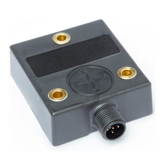
Beachten Sie das gleichmäßige Anzugsmoment von 1.5 … 2.5 Nm der Schrauben. Die Seite mit den markierten Achsen und dem Typenschild ist die Oberseite des Inklinometers. Ausgangspunkt Mitte Winkelstellung (Werkseinstellung) Z = 0° Abb. 1: Anzahl Achsen 1 IK360L · Datum 01.09.2020 · Art. Nr. 89208 · Änd. Stand 198/20... -
Page 6: Elektrische Installation
Schirmbleche oder metallisierte Gehäuse vorzusehen. Das Anschlusskabel ist mit einer Kabelklemme im Abstand von 10 ... 12 cm vom Sensor zu fixieren, um unbeabsichtigtes Verstellen des Inklinometer zu vermeiden. IK360L · Datum 01.09.2020 · Art. Nr. 89208 · Änd. Stand 198/20... -
Page 7: Inbetriebnahme
2 Achsen: für die X-Achse Pin 5 und 4, für die Y-Achse Pin 7 und 4, siehe Kapitel 4.2. 00.00 V Ausgang Z-Achse Folgeelektronik Abb. 3: Analoger Spannungsausgang IK360L · Datum 01.09.2020 · Art. Nr. 89208 · Änd. Stand 198/20... - Page 8 Beispiel: Uout = 1 V Positionswinkel = (1 V - 5 V) / (0.0625 V pro °) = -64° -40 -30 -20 -10 10 20 30 40 50 60 Winkel (°) X-Achse IK360L · Datum 01.09.2020 · Art. Nr. 89208 · Änd. Stand 198/20...
-
Page 9: Analoger Stromausgang
Widerstand (Hinweis: RLast ≤270 Ω) gemessen werden. 4 mA Ausgang X-Achse Folgeelektronik Beispiel für RL = 270 Ω: Vout = 270 Ω * 4 mA Vout = 1.08 V 1.08 V RLast ≤270 Ω Vout Abb. 4: Analoger Stromausgang IK360L · Datum 01.09.2020 · Art. Nr. 89208 · Änd. Stand 198/20... - Page 10 Beispiel: Iout = 8.31 mA Positionswinkel = (8.31 mA - 12 mA) / (0.1 mA pro °) = -36.9° -40 -30 -20 -10 10 20 30 40 50 60 Winkel (°) X-Achse IK360L · Datum 01.09.2020 · Art. Nr. 89208 · Änd. Stand 198/20...
-
Page 11: Transport, Lagerung, Wartung Und Entsorgung
Stoffe und sind zugleich Wertstoffträger. Der Inklinometer muss deshalb nach seiner endgültigen Stilllegung einem Recycling zuge- führt werden. Die Umweltrichtlinien des jeweiligen Landes müssen hierzu beachtet werden. IK360L · Datum 01.09.2020 · Art. Nr. 89208 · Änd. Stand 198/20... -
Page 12: Zubehör Anschluss-Stecker
4. Schirm kürzen und umlegen. klemmen (entspr. Anschlussplan Kapitel 4.2). 5. Litzen in Einsatz 6. Teile montieren. Schirm wird um Schirmring gelegt. 7. Druckschraube mit Kupplunghülse verschrauben. Abb. 5: Gegenstecker M12 gerade IK360L · Datum 01.09.2020 · Art. Nr. 89208 · Änd. Stand 198/20... -
Page 13: Technische Daten
IP6K9K ISO 20653, verbaut mit geeigne- tem Gegenstecker Schockfestigkeit ≤1000 m/s , 6 ms EN 60068-2-27 Vibrationsfestigkeit 1.5 mm, 10 … 58 Hz EN 60068-2-6 ≤200 m/s , 58 Hz … 2 kHz EN 60068-2-6 IK360L · Datum 01.09.2020 · Art. Nr. 89208 · Änd. Stand 198/20... - Page 14 5.2 Analog current output 6 Transport, Storage, Maintenance and Disposal 7 Accessory connector 7.1 Mating connector M12 straight inclusive cable 7.2 Straight mating connector M12 8 Technical data IK360L · Date 01.09.2020 · Art. No. 89208 · Mod. status 198/20...
-
Page 15: Documentation
Danger that may cause serious bodily harm, property damage or WARNING unplanned device reactions if you disregard the instructions given. IK360L · Date 01.09.2020 · Art. No. 89208 · Mod. status 198/20... -
Page 16: Target Group
• are authorized to commission, earth and label circuits and devices/ systems in accordance with the safety standards. 2.4 Basic safety information Danger of explosion DANGER ` Do not use the inclinometer in explosive zones. IK360L · Date 01.09.2020 · Art. No. 89208 · Mod. status 198/20... -
Page 17: Identification
4 Installation 4.1 Mechanical mounting The IK360L is a pre-calibrated instrument that can be put into operation immediately. The mounting area must be level, free from dust and grease. Use 3 pieces of M4 cylinder bolts for fastening. Ensure a uniform bolt tightening torque of 1.5 …... -
Page 18: Electrical Installation
Z axis Output U/I X axis Output U/I viewing side = SET1 SET1 plug-in side Do Not Connect Y axis Output U/I Do Not Connect Do Not Connect IK360L · Date 01.09.2020 · Art. No. 89208 · Mod. status 198/20... -
Page 19: Commissioning
Position angle (in °) = (10 V) / (0.02777 Volt pro °) Example: Uout = 1.6662 V Position angle = (1.6662 V) / (0.02777 V pro °) = 60° 359.9 Angle (°) IK360L · Date 01.09.2020 · Art. No. 89208 · Mod. status 198/20... -
Page 20: Analog Current Output
2 axes: for X axis pins 5 and 4, for Y axis pins 7 and 4, see chapter 4.2. You can measure the Iout current directly, or indirectly as voltage using load- resistance (note: RLoad ≤270 Ω). IK360L · Date 01.09.2020 · Art. No. 89208 · Mod. status 198/20... - Page 21 Position angle (in °) = (Iout - 12 mA) / (0.1 mA pro °) Example: Iout = 8.31 mA Position angle = (8.31 mA - 12 mA) / (0.1 mA pro °) = -36.9° IK360L · Date 01.09.2020 · Art. No. 89208 · Mod. status 198/20...
-
Page 22: Transport, Storage, Maintenance And Disposal
• Do not damage connections through mechanical or thermal impact. • Prior to installation inspect the inclinometer for transport damages. Do not install damaged inclinometer. Maintenance With correct installation according to chapter the inclinometer requires no maintenance. IK360L · Date 01.09.2020 · Art. No. 89208 · Mod. status 198/20... -
Page 23: Accessory Connector
4. Shorten and turn down screen. (follow connection diagram chapter 4.2). 5. Clamp wires into socket 6. Mount parts . Place screen around screen ring 7. Screw pressure screw on coupling sleeve IK360L · Date 01.09.2020 · Art. No. 89208 · Mod. status 198/20... -
Page 24: Technical Data
System data Additional information Resolution 0.01° Measuring range 360° 1 axis X and Y = -80 … 80° 2 axes Ambient conditions Additional information Ambient temperature -40 … 85 °C IK360L · Date 01.09.2020 · Art. No. 89208 · Mod. status 198/20... - Page 25 ISO 20653, installed with suit- able mating connector Shock resistance ≤1000 m/s , 6 ms EN 60068-2-27 Vibration resistance 1.5 mm, 10 … 58 Hz EN 60068-2-6 ≤200 m/s , 58 Hz … 2 kHz EN 60068-2-6 IK360L · Date 01.09.2020 · Art. No. 89208 · Mod. status 198/20...
- Page 26 IK360L...
- Page 27 IK360L...
- Page 28 SIKO GmbH Weihermattenweg 2 79256 Buchenbach Telefon/Phone + 49 7661 394-0 Telefax/Fax + 49 7661 394-388 E-Mail info@siko-global.com Internet www.siko-global.com Service support@siko-global.com...
Need help?
Do you have a question about the IK360L and is the answer not in the manual?
Questions and answers