
Subscribe to Our Youtube Channel
Related Manuals for SCHUNK JGZ 40


Summary of Contents for SCHUNK JGZ 40
- Page 1 Assembly and Operating Manual JGZ 3-finger centric gripper Original operating manual...
- Page 2 Imprint Imprint Copyright: This manual is protected by copyright. The author is SCHUNK SE & Co. KG. All rights reserved. Technical changes: We reserve the right to make alterations for the purpose of technical improvement. Document number: 389161 Version: 17.00 | 21/07/2023 | en...
-
Page 3: Table Of Contents
Table of contents Table of Contents 1 General ..................... 5 About this manual................1.1.1 Presentation of Warning Labels ............. 1.1.2 Definition of Terms ..............1.1.3 Applicable documents ..............1.1.4 Sizes..................1.1.5 Variants ................... 1.2 Warranty ................... 1.3 Scope of delivery................. 1.3.1 Accessory pack................ - Page 4 Table of contents 5.2 Connections ..................20 5.2.1 Mechanical connection..............20 5.2.2 Pneumatic connection..............21 5.3 Mounting the sensor................23 5.3.1 Overview of sensors ..............23 5.3.2 Setting dimensions for magnetic switches ........23 5.3.3 Switch-off hysteresis for magnetic switches ........24 5.3.4 Turn control cam................
-
Page 5: General
General 1 General 1.1 About this manual This manual contains important information for a safe and appropriate use of the product. This manual is an integral part of the product and must be kept accessible for the personnel at all times. Before starting work, the personnel must have read and understood this operating manual. -
Page 6: Applicable Documents
Assembly and operating manuals of the accessories * The documents labeled with an asterisk (*) can be downloaded from schunk.com. 1.1.4 Sizes This operating manual applies to the following sizes: JGZ 40 JGZ 50 JGZ 64 JGZ 80 JGZ 100... -
Page 7: Accessory Pack
6 x Centering sleeves for mounting 2 x O-ring for hose-free direct connection 2 x screw plug for hose connection 2 x cylindrical pin for mounting Accessory pack for ID number JGZ 40 5521694 JGZ 50 5520796 JGZ 64 5512728... -
Page 8: Basic Safety Notes
Use of unauthorized spare parts Using unauthorized spare parts can endanger personnel and damage the product or cause it to malfunction. Use only original spare parts or spares authorized by SCHUNK. 2.4 Gripper fingers Requirements of gripper fingers Accumulated energy can make the product unsafe and risk the danger of serious injuries and considerable material damage. -
Page 9: Ambient Conditions And Operating Conditions
Basic safety notes Execute the gripper fingers in such a way that the product reaches either the "open" or "closed" position in a de- energized state. Only change gripper fingers if no residual energy can be released. Make sure that the product and the top jaws are a sufficient size for the application. -
Page 10: Personal Protective Equipment
Basic safety notes Service personnel of Due to its technical training, knowledge and experience, service the manufacturer personnel of the manufacturer is able to perform the delegated tasks and to recognize and avoid possible dangers. 2.7 Personal protective equipment Use of personal protective equipment Personal protective equipment serves to protect staff against danger which may interfere with their health or safety at work. -
Page 11: Transport
Basic safety notes 2.9 Transport Handling during transport Incorrect handling during transport may impair the product's safety and cause serious injuries and considerable material damage. When handling heavy weights, use lifting equipment to lift the product and transport it by appropriate means. Secure the product against falling during transportation and handling. -
Page 12: Protection During Handling And Assembly
Basic safety notes Do not reach into the open mechanism or movement area of the product during operation. 2.12.1 Protection during handling and assembly Incorrect handling and assembly Incorrect handling and assembly may impair the product's safety and cause serious injuries and considerable material damage. Have all work carried out by appropriately qualified personnel. -
Page 13: Protection Against Electric Shock
Basic safety notes To avoid accidents and/or material damage, human access to the movement range of the machine must be restricted. Limit/ prevent accidental access for people in this area due through technical safety measures. The protective cover and protective fence must be rigid enough to withstand the maximum possible movement energy. -
Page 14: Notes On Particular Risks
Basic safety notes 2.13 Notes on particular risks DANGER Risk of fatal injury from suspended loads! Falling loads can cause serious injuries and even death. Stand clear of suspended loads and do not step within their swiveling range. Never move loads without supervision. Do not leave suspended loads unattended. - Page 15 Secure the end positions of the product with SCHUNK SDV-P pressure maintenance valves. 17.00 | JGZ | Assembly and Operating Manual | en | 389161...
-
Page 16: Technical Data
* For use in dirty ambient conditions (e.g. sprayed water, vapors, abrasion or processing dust) SCHUNK offers corresponding product options as standard. SCHUNK also offers customized solutions for special applications in dirty ambient conditions. 17.00 | JGZ | Assembly and Operating Manual | en | 389161... -
Page 17: Design And Description
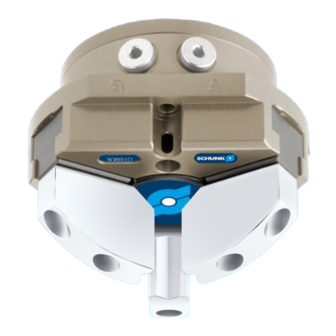
Design and description 4 Design and description 4.1 Design 3-finger centric gripper Housing Base jaw Compressed air main connection 4.2 Description Universal 2-finger centric gripper with T-slot guidance. 17.00 | JGZ | Assembly and Operating Manual | en | 389161... -
Page 18: Assembly
Assembly 5 Assembly 5.1 Installing and connecting WARNING Risk of injury due to unexpected movements! If the power supply is switched on or residual energy remains in the system, components can move unexpectedly and cause serious injuries. Before starting any work on the product: Switch off the power supply and secure against restarting. - Page 19 Assembly ð Observe the maximal tightening torque, admissible screw-in depth and, if necessary, strength class. Secure the gripper fingers to the base jaws, } 5.2.1 [/ 20]. ð Use centering sleeves from the enclosed accessory pack. If necesssary, mount the pressure piece for spring-supported positioning of the work piece against a stop, [/ 21].
-
Page 20: Connections
Assembly 5.2 Connections 5.2.1 Mechanical connection Evenness of the The values apply to the whole mounting surface to which the mounting surface product is mounted. Edge length Permissible unevenness < 100 < 0.02 > 100 < 0.05 Tab.: Requirements for evenness of the mounting surface (Dimensions in mm) Requirements for If the adapter plate has bores or recesses and therefore the customer adapter... -
Page 21: Pneumatic Connection
Assembly Item Mounting with gripping force maintenance (AS / IS) Fitting hole for cylindrical Ø2H7 Ø3H7 Ø4H7 Ø5H7 Ø5H7 Ø6H7 Ø 6H7 pins * Possible recess in the adapter plate Max. recess [mm] Ø24 Ø32 Ø40 Ø55 Ø70 Ø85 Ø115 Affixing the gripper fingers Mounting screw(2x) M2.5 Max. - Page 22 Assembly are also offered with mechanical gripping force via springs, which also ensure a minimum clamping force in the event of a pressure drop. Air connections Main connections (Hose connection) (A = open, B = close) Hose-free direct connection (a = open, b = close) Air purge connection Hose-free direct connection Product...
-
Page 23: Mounting The Sensor
– The assembly and operating manual and catalog datasheet are included in the scope of delivery for the sensors and are available at schunk.com. Information on handling sensors is available at schunk.com or from SCHUNK contact persons. 5.3.1 Overview of sensors... -
Page 24: Switch-Off Hysteresis For Magnetic Switches
The magnetic switch MMS 22-PI1 can be adjusted and taught in two ways. "Standard mode" allows for quick installation on the T-nut preset by SCHUNK in the groove or the defined setting dimension "l1." In "Optimal Mode", the sensor identifies the optimal position in the groove itself. -
Page 25: Turn Control Cam
Assembly 7 mm * 20% = 1.4 mm 5.3.4 Turn control cam Turn control cam, example control cam for inductive monitoring Depending on the jaw stroke, it may be necessary to change the alignment of the control cam for the sensors IN 80 and RMS 80. In the image, the installation situation (A) shows the control cam in the delivery state of the product and the installation situation (B) shows the turned control cam. - Page 26 Assembly Position "Gripper open" or "Part gripped (I.D. gripping)" Slide the sensor 1 (1) or sensor 2 (1) to the stop into the bracket (2). Tighten the screw (3) on the bracket (2). Tightening torque: 0.2 Nm Open gripper or grip part. Undo the screw (4).
-
Page 27: Mounting Magnetic Switch Mms 22
Assembly Turn the screw (5) to push the position of the control cam (6). ð Slide control cam (6) outwards until the sensor 3 (1) no longer responds. Move the control cam (6) back towards the inside until the sensor 3 (1) begins to switch. Tighten screw (4) and in doing so press the control cam in the direction of the gripper fingers. -
Page 28: Mounting Programmable Mms 22-Pi2 Magnetic Switch
Assembly Secure the sensor 1 (1) using the set-screw (4). Tightening torque: 10 Ncm Bring product into the "Gripper open" or "Part gripped" position and test the function. Position "Gripper closed" or "Part gripped (O.D. gripping)" Bring product in the position in which it is to be set. If necessary remove T-nut (3). -
Page 29: Mounting Programmable Magnetic Switch Mms-P 22
Assembly Adjust sensor (1), see sensor assembly and operating manual. 5.3.8 Mounting programmable magnetic switch MMS-P 22 CAUTION Risk of damage to the sensor during assembly! Observe the maximal tightening torque. NOTE If there is no T-nut available, slide the sensor according to dimension I1 into the groove (2), [/ 23]. -
Page 30: Mounting Programmable Magnetic Switch Mms 22-Pi1
Assembly NOTE If there is no T-nut available, slide the sensor according to dimension I1 into the groove (2), [/ 23]. } 5.3.2 Turn the sensor (1) into the groove (2). OR: Slide the sensor (1) into the groove (2) until the sensor (1) stops at the T-nut (3). - Page 31 The magnetic switch MMS 22-PI1 can be adjusted and taught in two ways. "Standard mode" allows for quick installation on the T-nut preset by SCHUNK in the groove or the defined setting dimension "l1." In "Optimal Mode", the sensor identifies the optimal position in the groove itself.
-
Page 32: Mounting Analog Position Sensor Aps-Z80
With O.D. gripping the "Gripper closed" position and with I.D. gripping the "Gripper opened" position cannot be queried. Should you have questions, do not hesitate to contact SCHUNK. Actual signal Optimum signal Stroke [mm] Analog signal on O.D. - Page 33 ð SCHUNK recommends the adhesive Loctite 290 or 638. Slide control cam (6) into the base jaw to the stop. ð Ensure that the higher front side of the control cam (6) is pointing outwards.
-
Page 34: Mounting Reed Switch Rms 80
Assembly Tighten the screw (3) on the bracket (2). Tightening torque: 0.2 Nm Adjust sensor (1), see the Sensor Assembly and Operating Manual. 5.3.12 Mounting reed switch RMS 80 CAUTION Blockade of the gripper after setting or replacing of the switching cam! The switching cam can be tilt in the guide, if it was not fixed exactly in the base jaw. -
Page 35: Mounting Flexible Position Sensor Fps
Assembly ð Switching point is set. Bring product into the "Gripper open" or "Part gripped" position and test the function. NOTE If the switching position cannot be queried, it may be that the alignment of the control cam has to be changed, } 5.3.4 [/ 25]. -
Page 36: Mounting Analog Position Sensor Aps-M1
Assembly Move product to the "gripper open" position. Loosen screw (4) and remove control cam (6) for the inductive monitoring from the base jaw. Remove screw (5) from the base jaw. Slide control cam (7) from the mounting kit with the recess at the front into the base jaw. -
Page 37: Mounting The Radio System Rss-R1/T2
ð Make sure that there is no adhesive on the bottom of the control cam (6), which comes into contact with the sensor. ð SCHUNK recommends the adhesive Loctite 290 or 638. Slide control cam (6) out of the mounting kit front into the base jaw. - Page 38 Assembly Adjust the sensor, see the assembly and operating manual for the sensor. Connect the radio system, see the assembly and operating manual for the radio system. 17.00 | JGZ | Assembly and Operating Manual | en | 389161...
-
Page 39: Troubleshooting
Unused air connections open. Close unused air connections. Flow control valve closed. Open the flow control valve. Component part defective. Replace component or send it to SCHUNK for repair. 6.2 Product is not executing the complete stroke Possible cause Corrective action Dirt deposits between cover and piston. -
Page 40: Gripping Force Is Dropping
Pressure drops below minimum. Check air supply. } 3 [/ 16] Component part defective. Replace component or send it to SCHUNK for repair. 6.5 Product does not achieve the opening and closing times Possible cause Corrective action Compressed air lines are not installed If present: Open the flow control couplings on optimally. -
Page 41: Maintenance
Maintenance 7 Maintenance 7.1 Notes Original spare parts Use only original spare parts of SCHUNK when replacing spare and wear parts. Replacement of the housing and base jaws The base jaws and the guides in the housing are matched to each other. -
Page 42: Lubricants/Lubrication Points
Maintenance 7.3 Lubricants/Lubrication points During maintenance, treat all greased areas with lubricant. Thinly apply lubricant with a lint-free cloth. SCHUNK recommends the lubricants listed. Lubricant point Lubricant Metallic sliding surfaces Rivolta F.L.G. GT-2 All seals Rivolta F.L.G. GT-2 Bore hole at the piston Rivolta F.L.G. -
Page 43: Disassembly And Assembly
Maintenance 7.4 Disassembly and assembly 7.4.1 Disassemble the product 7.4.1.1 Version without gripping force maintenance Position of the item numbers } 7.5 [/ 50] WARNING Risk of injury due to unexpected movements! If the power supply is switched on or residual energy remains in the system, components can move unexpectedly and cause serious injuries. - Page 44 Maintenance WARNING Risk of injury due to spring forces! Products that use spring force or have gripping force maintenance contain parts that are under spring tension. This can cause components to move unexpectedly when being dismantled, which may result in serious injuries. Carefully dismantle the product.
- Page 45 Maintenance 7.4.1.3 Version with gripping force maintenance I.D. Position of the item numbers } 7.5 [/ 50] WARNING Risk of injury due to unexpected movements! If the power supply is switched on or residual energy remains in the system, components can move unexpectedly and cause serious injuries.
-
Page 46: Assembling The Product
Maintenance 7.4.2 Assembling the product 7.4.2.1 Notes for assembly Assembly takes place in the opposite order to disassembly. Observe the following: For variant with "O.D. gripping" maintenance of gripping force (AS) – Sizes 40-100: assemble cylinder piston using an assembly device, } 7.4.2.3 [/ 47] –... - Page 47 Position of the item numbers } 7.5 [/ 50] Installation of the sizes 40-100 using an assembly device Assembly device 1 cylinder piston Item Type JGZ 40 JGZ 50 JGZ 64 JGZ 80 Assembly device 1 Cylindrical pin Ø2H7 Ø3H7 Ø4H7 Ø5H7 Ø5H7...
- Page 48 Maintenance Assembly of sizes 125-160 with two assembly devices Installing cylinder pistons with a assembly devices 1 and 2 Item Type JGZ 125 JGZ 160 Device 1 Device 2 Cylindrical pin Ø6H7 (2x) Ø6H7 (2x) Screw ISO 4762 M8x50 M8x60 Screw ISO 4762 M8x40 M8x45...
- Page 49 Maintenance 7.4.2.4 Assembly device for cylinder piston with gripping force maintenance Assembly devices Assembly device 1 Assembly device 2 Tab.: Assembly device 1 - dimensions in mm Size Ø A Ø d 27.5 Ø d ±0.02 36.0 45.0 56.0 70.0 90.0 29.9 41.2...
-
Page 50: Assembly Drawing
Maintenance Tab.: Assembly device 2 (with assembly device 1) - dimensions in mm Size Ø A Ø C Ø d 94.5 127.5 Ø d 94.5 127.5 Ø d Ø d Ø d ±0.02 112.0 146.0 97.0 126.4 56.0 73.0 56.0 73.0 97.0 126.4... - Page 51 Maintenance Assembly of the variants O.D. gripping (AS) / I.D. gripping (IS) / without maintenance of gripping force unit Wearing part, replace during maintenance. Included in the seal kit. Seal kit can only be ordered completely. Positions are adapted to each other and can not be replaced by the customer. from size 125 **** from size 160...
-
Page 52: Translation Of The Original Declaration Of Incorporation
8 Translation of the original declaration of incorporation in terms of the Directive 2006/42/EG, Annex II, Part 1 Section B. Manufacturer/ SCHUNK SE & Co. KG Distributor Toolholding and workholding | Gripping Technology | Automation technology Bahnhofstr. 106 - 134... -
Page 53: Ukca Declaration Of Incorporation
UKCA declaration of incorporation 9 UKCA declaration of incorporation in accordance with the Supply of Machinery (Safety) Regulations 2008. Manufacturer/ SCHUNK Intec Limited Distributor Clamping and gripping technology 3 Drakes Mews, Crownhill MK8 0ER Milton Keynes We hereby declare that on the date of the declaration the following partly completed machine complied with all basic safety and health regulations found in the "Supply of Machinery (Safety) Regulations 2008". -
Page 54: Information On The Rohs Directive, Reach Regulation And Substances Of Very High Concern (Svhc)
"on the restriction of the use of certain hazardous substances in electrical and electronic equipment (RoHS)", or fulfill their intended function only as part of one. Therefore products from SCHUNK do not fall within the scope of the directive at this time. REACH Regulation Products from SCHUNK fully comply with the regulations of Regulation (EC) No. 1907/2006... - Page 55 17.00 | JGZ | Assembly and Operating Manual | en | 389161...
- Page 56 SCHUNK SE & Co. KG Toolholding and workholding | Gripping Technology | Automation technology Bahnhofstr. 106 - 134 D-74348 Lauffen/Neckar Tel. +49-7133-103-0 Fax +49-7133-103-2399 info@de.schunk.com schunk.com Folgen Sie uns I Follow us Wir drucken nachhaltig I We print sustainable...
Need help?
Do you have a question about the JGZ 40 and is the answer not in the manual?
Questions and answers