
Subscribe to Our Youtube Channel
Related Manuals for SCHUNK JGP-P


Summary of Contents for SCHUNK JGP-P
- Page 1 Translation of Original Operating Manual Assembly and Operating Manual JGP-P 2-finger parallel gripper...
- Page 2 Imprint Imprint Copyright: This manual is protected by copyright. The author is SCHUNK GmbH & Co. KG. All rights reserved. Technical changes: We reserve the right to make alterations for the purpose of technical improvement. Document number: 1469637 Version: 02.00 | 05/10/2021 | en...
-
Page 3: Table Of Contents
Assembly and settings .................... 20 Installing and connecting.................. 20 Connections...................... 22 5.2.1 Mechanical connection................ 22 5.2.2 Pneumatic connection................ 26 Attaching additional structure................ 28 Mounting the sensor .................. 30 5.4.1 Overview of sensors ................ 30 02.00 | JGP-P | Assembly and Operating Manual | en | 1469637... - Page 4 Installation position of the magnets in the piston.......... 55 Tightening torques ..................... 56 Assembly drawing.................... 57 Translation of original declaration of incorporation .......... 61 Annex to Declaration of Incorporation .............. 62 02.00 | JGP-P | Assembly and Operating Manual | en | 1469637...
-
Page 5: General
• Catalog data sheet of the purchased product * • Assembly and operating manuals of the accessories * The documents marked with an asterisk (*) can be downloaded on our homepage schunk.com 02.00 | JGP-P | Assembly and Operating Manual | en | 1469637... -
Page 6: Sizes
JGP-P 50-160 200-240 Warranty duration [months] or maximum cycles [mil.] * One cycle consists of a complete gripping process: "Open gripper" (release workpiece) and "Close gripper" (grip workpiece). 02.00 | JGP-P | Assembly and Operating Manual | en | 1469637... -
Page 7: Scope Of Delivery
A wide range of accessories are available for this product For information regarding which accessory articles can be used with the corresponding product variants, see catalog data sheet. 02.00 | JGP-P | Assembly and Operating Manual | en | 1469637... -
Page 8: Spare Parts Packages
1326027 JGP-P 125 1326031 JGP-P 160 1326040 JGP-P 200 1326045 JGP-P 200-AS 1477531 JGP-P 200-IS 1489746 JGP-P 240 1326048 JGP-P 240-AS 1489780 JGP-P 240-IS 1489781 JGP-P 300 1479146 02.00 | JGP-P | Assembly and Operating Manual | en | 1469637... -
Page 9: Basic Safety Notes
• Any utilization that exceeds or differs from the appropriate use is regarded as misuse. 02.00 | JGP-P | Assembly and Operating Manual | en | 1469637... -
Page 10: Constructional Changes
• Make sure that the product is used only in the context of its } 3 defined application parameters, [/ 18]. 02.00 | JGP-P | Assembly and Operating Manual | en | 1469637... -
Page 11: Personnel Qualification
Due to its technical training, knowledge and experience, service the manufacturer personnel of the manufacturer is able to perform the delegated tasks and to recognize and avoid possible dangers. 02.00 | JGP-P | Assembly and Operating Manual | en | 1469637... -
Page 12: Personal Protective Equipment
• Eliminate any malfunction immediately. • Observe the care and maintenance instructions. • Observe the current safety, accident prevention and environmental protection regulations regarding the product's application field. 02.00 | JGP-P | Assembly and Operating Manual | en | 1469637... -
Page 13: Transport
The incorrect handling of disposal may impair the product's safety and cause serious injuries as well as considerable material and environmental harm. • Follow local regulations on dispatching product components for recycling or proper disposal. 02.00 | JGP-P | Assembly and Operating Manual | en | 1469637... -
Page 14: Fundamental Dangers
Falling loads may cause serious injuries and even death. • Stand clear of suspended loads and do not step into their swiveling range. • Never move loads without supervision. • Do not leave suspended loads unattended. 02.00 | JGP-P | Assembly and Operating Manual | en | 1469637... -
Page 15: Protection During Commissioning And Operation
Before starting up the machine or automated system, check that the EMERGENCY STOP system is working. Prevent operation of the machine if this protective equipment does not function correctly. 02.00 | JGP-P | Assembly and Operating Manual | en | 1469637... -
Page 16: Protection Against Electric Shock
Before starting any work on the product: Switch off the power • supply and secure against restarting. Make sure, that no residual energy remains in the system. • 02.00 | JGP-P | Assembly and Operating Manual | en | 1469637... - Page 17 EN IEC 61000, are not exceeded. Take suitable protective measures to secure the danger zone. • 02.00 | JGP-P | Assembly and Operating Manual | en | 1469637...
-
Page 18: Technical Data
JGP-P Ambient temperature [°C] min. max. Protection class IP Noise emission [dB(A)] ≤70 More technical data is included in the catalog data sheet. Whichever is the latest version. 02.00 | JGP-P | Assembly and Operating Manual | en | 1469637... -
Page 19: Design And Description
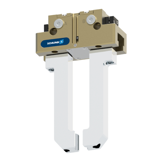
Groove for magnetic switch Housing 4.2 Description Universal 2-finger parallel gripper with a high gripping force and high maximum moments due to the use of a T-slot guidance. 02.00 | JGP-P | Assembly and Operating Manual | en | 1469637... -
Page 20: Assembly And Settings
A jaw movement always has to be without jerks and bounce. • You must therefore implement sufficient reduction and/or • damping. Observe the diagrams and information in the catalog data • sheet. 02.00 | JGP-P | Assembly and Operating Manual | en | 1469637... - Page 21 6. Attach additional structure to the product if necessary, } 5.3 [/ 28] 7. Connect the sensor, see assembly and operating manual of the sensor. } 5.4 8. Mount the sensor, [/ 30]. 02.00 | JGP-P | Assembly and Operating Manual | en | 1469637...
-
Page 22: Connections
Ø10 Ø14 Ø16 Ø16 Ø22 Thread in base jaws M10 M12 M12 M16 Mounting screw strength 12.9 class Max. depth of engagement 14.2 19.3 21.1 27.9 from locating surface [mm] 02.00 | JGP-P | Assembly and Operating Manual | en | 1469637... - Page 23 Side C Bore for mounting screws M2.5 M3 Mounting screw according DIN EN ISO 4762 to standard Max. strength class 8.8 Centering sleeve Ø5 Ø6 Ø8 Ø8 Ø10 02.00 | JGP-P | Assembly and Operating Manual | en | 1469637...
- Page 24 Side C Bore for mounting screws M10 M12 M16 Mounting screw according DIN EN ISO 4762 to standard Max. strength class 8.8 Centering sleeve Ø12 Ø12 Ø14 Ø16 Ø22 02.00 | JGP-P | Assembly and Operating Manual | en | 1469637...
- Page 25 Ø3 Ø4 Ø4 Ø4 Ø5 Item Mounting JGP-P Thread in the housing Max. depth of engagement 10.9 from locating surface [mm] Centering sleeve Ø6 Ø8 Ø10 Ø10 Ø12 02.00 | JGP-P | Assembly and Operating Manual | en | 1469637...
-
Page 26: Pneumatic Connection
• Open only the air connections that are needed. • Close unused main air connections using the screw plugs from the enclosed pack. • For a hose-free direction connection, use the O-rings from the enclosed pack. 02.00 | JGP-P | Assembly and Operating Manual | en | 1469637... - Page 27 Air purge connection The air purge is used in order to make it more difficult for dirt and dust to penetrate into the product and the guiding areas. 02.00 | JGP-P | Assembly and Operating Manual | en | 1469637...
-
Page 28: Attaching Additional Structure
The external dimensions of the additional structure can exceed the external dimensions of the gripper but not interfere with the operating cycle of the gripper fingers. 02.00 | JGP-P | Assembly and Operating Manual | en | 1469637... - Page 29 With sizes 50 – 100 the threaded holes (5) of the cover (2) ✓ are used for securing the additional structure. From size 125, the additionally attached threaded holes (6) ✓ are used for securing the additional structure. 02.00 | JGP-P | Assembly and Operating Manual | en | 1469637...
-
Page 30: Mounting The Sensor
– – Analog magnetic switch – – MMS 22-A Analog position sensor APS-Z80 – – Flexible position sensor FPS – – – Analog position sensor APS-M1 – – 02.00 | JGP-P | Assembly and Operating Manual | en | 1469637... -
Page 31: Setting Dimensions For Magnetic Switches
• In "Optimal Mode", the sensor identifies the optimal position in the groove itself. SCHUNK recommends "Optimal Mode" for setting the sensors. Further information on the installation of the sensor, } 5.4.9 [/ 38] 02.00 | JGP-P | Assembly and Operating Manual | en | 1469637... -
Page 32: Switch-Off Hysteresis For Magnetic Switches
80-1 80-2 -2.6 -3.3 100-1 -2.7 100-2 -3.8 125-1 -3.8 +1.7 125-2 -7.8 -2.3 160-1 160-2 -4.2 -7.1 200-1 +2.2 200-2 -7.5 -3.6 240-1 240-2 -8.2 -4.6 300-1 02.00 | JGP-P | Assembly and Operating Manual | en | 1469637... -
Page 33: Mounting Inductive Proximity Switch In
2. Tighten the screw (3) on the bracket (2). Tightening torque: 0.2 Nm 3. Clamp the part to be gripped. 4. Loosen expander bolt (4) by unscrewing it from the control cam (6). 02.00 | JGP-P | Assembly and Operating Manual | en | 1469637... - Page 34 64 80 100 125 160 200 240 300 Max. tightening torque 0.2 0.2 0.3 0.3 0.4 0.4 0.4 0.4 [Nm] Max. adjusting torque 0.2 0.2 0.3 0.3 0.4 0.4 0.4 0.4 [Nm] 02.00 | JGP-P | Assembly and Operating Manual | en | 1469637...
-
Page 35: Mounting Mms 22 Magnetic Switch
4. Secure the sensor 2 (1) using the set-screw (4). Tightening torque: 10 Ncm 5. Bring product into the "Gripper closed" or "Part gripped" position and test the function. 02.00 | JGP-P | Assembly and Operating Manual | en | 1469637... -
Page 36: Mounting Programmable Mms 22-Pi2 Magnetic Switch
OR: Slide the sensor (1) into the groove (2) until the sensor (1) stops at the T-nut (3). 2. Secure the sensor (1) using the set-screw (4). Tightening torque: 10 Ncm 3. Adjust sensor (1), see sensor assembly and operating manual. 02.00 | JGP-P | Assembly and Operating Manual | en | 1469637... -
Page 37: Mounting Programmable Mms 22-P 22 Magnetic Switch
OR: Slide the sensor (1) into the groove (2) until the sensor (1) stops at the T-nut (3). 2. Secure the sensor (1) using the set-screw (4). Tightening torque: 10 Ncm 3. Adjust sensor (1), see sensor assembly and operating manual. 02.00 | JGP-P | Assembly and Operating Manual | en | 1469637... -
Page 38: Mounting Mms 22-Pi1 Programmable Magnetic Switch
4. Secure the sensor 1 (1) using the set-screw (4). Tightening torque: 10 Ncm 5. Hold teaching tool to the sensor 1 (1) to confirm the position. The sensor 1 (1) has been taught in. ✓ 02.00 | JGP-P | Assembly and Operating Manual | en | 1469637... -
Page 39: Mounting The Magnetic Switch Mms 22-Iol
OR: Slide the sensor (1) into the groove (2) until the sensor (1) stops at the T-nut (3). 2. Secure the sensor (1) using the set-screw (4). Tightening torque: 10 Ncm 02.00 | JGP-P | Assembly and Operating Manual | en | 1469637... - Page 40 50 IS 125 IS 17.8 64 AS 17.8 160 AS 33.5 64 IS 35.8 160 IS 78.5 25.8 80 AS 25.8 200 AS 80 IS 43.8 200 IS 02.00 | JGP-P | Assembly and Operating Manual | en | 1469637...
-
Page 41: Mounting Analog Mms 22-A Magnetic Switch
SCHUNK. Size Stroke 1 Stroke 2 100% 100% JGP-P 50 4 mm 0.6 mm 2 mm 0.3 mm JGP-P 200 25 mm 3.75 mm 14 mm 2.1 mm 02.00 | JGP-P | Assembly and Operating Manual | en | 1469637... - Page 42 3. Mount a throttle reduction M5 - 0.8 (5) at both main connections "A" and "B". 4. Adjust sensor (1), see the Sensor Assembly and Operating Manual. 5. Remove throttle reduction (5) after finishing the sensor teaching process. 02.00 | JGP-P | Assembly and Operating Manual | en | 1469637...
-
Page 43: Mounting Analog Position Sensor Aps-Z80
Optimum signal Stroke [mm] Analog signal on O.D. gripping Actual signal Optimum signal Stroke [mm] Analog signal on I.D. gripping 1. Move product to the "gripper open" position. 02.00 | JGP-P | Assembly and Operating Manual | en | 1469637... -
Page 44: Mount The Flexible Position Sensor Fps
} 5.4.11 [/ 41] 1. Assembling the sensor, 2. Connect the control unit output and adjust the sensor (see assembly and operating manual of the sensor). 02.00 | JGP-P | Assembly and Operating Manual | en | 1469637... - Page 45 7. Slide the sensor (1) to the stop into the bracket (2). 8. Tighten the screw (3) on the bracket (2). Tightening torque: 0.2 Nm 9. Adjust sensor (1), see Translation of Sensor Assembly and Operating Manual. 02.00 | JGP-P | Assembly and Operating Manual | en | 1469637...
-
Page 46: Mounting Analog Position Sensor Aps-M1
6. Slide the sensor (1) to the stop into the bracket (2). 7. Tighten the screw (3) on the bracket (2). Tightening torque: 0.2 Nm 8. Connect the sensor, see assembly and operating manual of the sensor. 02.00 | JGP-P | Assembly and Operating Manual | en | 1469637... -
Page 47: Troubleshooting
One-way flow control valve is missing or Install and adjust one-way flow control adjustet incorrectly. valve. Loading too large. Check permissible weight and length of the gripper fingers. 02.00 | JGP-P | Assembly and Operating Manual | en | 1469637... -
Page 48: Product Does Not Achieve The Opening And Closing Times
Too much grease in the mechanical Clean and lubricate product. movement space. Pressure drops below minimum. Check air supply. } 3 [/ 18] Component part defective. Replace component or send it to SCHUNK for repair. 02.00 | JGP-P | Assembly and Operating Manual | en | 1469637... -
Page 49: Maintenance
CAUTION Material damage due to hardening lubricants! Lubricants harden more quickly at temperatures above 60°C, leading to possible product damage. Reduce the lubricant intervals accordingly. • 02.00 | JGP-P | Assembly and Operating Manual | en | 1469637... -
Page 50: Lubricants/Lubrication Points (Basic Lubrication)
When moving the gripper fingers, body parts may get squashed/ hit causing severe injuries. Do not interfere with moving parts during operation. • Observe position and direction of movement of the gripper • fingers. 02.00 | JGP-P | Assembly and Operating Manual | en | 1469637... -
Page 51: Replace Seals
13. Insert base jaws (3) into the housing (2).IMPORTANT! Observe installation position of the base jaws (3) in the housing (2). 14. Insert wedge hook (1) into the housing (2). 02.00 | JGP-P | Assembly and Operating Manual | en | 1469637... -
Page 52: Replace Seal (Variant With Gripping Force Maintenance "O.d. Gripping")
During assembly, the cylinder piston must be aligned precisely. We therefore recommend having SCHUNK change the seals. } 5.2.2 1. Remove all compressed air lines, [/ 26]. 2. Remove product from the system/machine. 3. Remove the cover (12). 02.00 | JGP-P | Assembly and Operating Manual | en | 1469637... - Page 53 21. Fasten the cover (6) with the screws. } 7.7 [/ 56] Tightening torque: 22. Fasten the cover (12) with the screws. 23. Mount product onto the system/machine. 24. Connect all compressed air lines. 02.00 | JGP-P | Assembly and Operating Manual | en | 1469637...
-
Page 54: Replace Seal (Variant With Gripping Force Maintenance "I.d. Gripping")
11. Attach new seals (2 and 9) from the seal kit. 12. Re-lubricating guiding areas 13. Insert base jaws (3) into the housing (10). IMPORTANT! Observe installation position of the base jaws (3) in the housing (10). 02.00 | JGP-P | Assembly and Operating Manual | en | 1469637... -
Page 55: Installation Position Of The Magnets In The Piston
Size Variant without maintenance of gripping force JGP-P 40 JGP-P 50 - 240 JGP-P 300 Variant with "O.D. gripping" maintenance of gripping force JGP-P 40 O.D. JGP-P 50-125 O.D. 02.00 | JGP-P | Assembly and Operating Manual | en | 1469637... -
Page 56: Tightening Torques
JGP-P 300: Tightening torques for screws – details in Nm Size Item 40 Item 45 Item 41 Item 46 JGP-P 300 -1 JGP-P 300 O.D. JGP-P 300 I.D. 02.00 | JGP-P | Assembly and Operating Manual | en | 1469637... -
Page 57: Assembly Drawing
Maintenance 7.8 Assembly drawing JGP-P 40 – 240 standard * Position of the magnets in the piston depends on the variant and size, } 7.6 [/ 55]. 02.00 | JGP-P | Assembly and Operating Manual | en | 1469637... - Page 58 Maintenance JGP-P 300 standard * Position of the magnets in the piston depends on the variant and size, } 7.6 [/ 55]. 02.00 | JGP-P | Assembly and Operating Manual | en | 1469637...
- Page 59 Maintenance JGP-P 40 – 160 with maintenance of gripping force O.D. gripping (A) and I.D. gripping (B) * Position of the magnets in the piston depends on the variant and size, } 7.6 [/ 55]. 02.00 | JGP-P | Assembly and Operating Manual | en | 1469637...
- Page 60 Maintenance JGP-P 200 – 300 with maintenance of gripping force O.D. gripping (A) and I.D. gripping (B) * Position of the magnets in the piston depends on the variant and size, } 7.6 [/ 55]. 02.00 | JGP-P | Assembly and Operating Manual | en | 1469637...
-
Page 61: Translation Of Original Declaration Of Incorporation
Person authorized to compile the technical documentation: Robert Leuthner, Address: see manufacturer's address Lauffen/Neckar, June 2021 p.p. Ralf Winkler; Head of Technology & Engineering, Mechanics Gripping Systems 02.00 | JGP-P | Assembly and Operating Manual | en | 1469637... -
Page 62: Annex To Declaration Of Incorporation
Risks due to falling or ejected objects 1.3.4 Risks due to surfaces, edges or angles 1.3.5 Risks related to combined machinery 1.3.6 Risks related to variations in operating conditions 02.00 | JGP-P | Assembly and Operating Manual | en | 1469637... - Page 63 Risk of slipping, tripping or falling 1.5.16 Lightning Maintenance 1.6.1 Machinery maintenance 1.6.2 Access to operating positions and servicing points 1.6.3 Isolation of energy sources 1.6.4 Operator intervention 1.6.5 Cleaning of internal parts 02.00 | JGP-P | Assembly and Operating Manual | en | 1469637...
- Page 64 Supplementary essential health and safety requirements for machinery intended for underground work Supplementary essential health and safety requirements for machinery presenting particular hazards due to the lifting of persons 02.00 | JGP-P | Assembly and Operating Manual | en | 1469637...
- Page 68 Translation of Original Operating Manual SCHUNK GmbH & Co. KG Clamping and gripping technology Bahnhofstr. 106 - 134 D-74348 Lauffen/Neckar Tel. +49-7133-103-0 Fax +49-7133-103-2399 info@de.schunk.com schunk.com Folgen Sie uns I Follow us...
Need help?
Do you have a question about the JGP-P and is the answer not in the manual?
Questions and answers