
Subscribe to Our Youtube Channel
Related Manuals for SCHUNK JGP-P


Summary of Contents for SCHUNK JGP-P
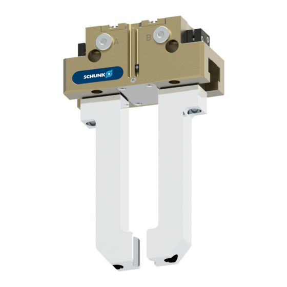
- Page 1 Assembly and Operating Manual JGP-P 2-finger parallel gripper Translation of Original Operating Manual...
- Page 2 Imprint Imprint Copyright: This manual is protected by copyright. The author is SCHUNK SE & Co. KG. All rights reserved. Technical changes: We reserve the right to make alterations for the purpose of technical improvement. Document number: 1469637 Version: 06.00 | 02/02/2024 | en...
-
Page 3: Table Of Contents
3 Technical data ..................18 4 Design and description ................19 4.1 Design ....................19 4.2 Description ..................19 5 Assembly and settings ................20 5.1 Installing and connecting ..............20 06.00 | JGP-P | Assembly and Operating Manual | en | 1469637... - Page 4 8 Translation of the original declaration of incorporation ......... 65 9 UKCA declaration of incorporation ............66 10 Information on the RoHS Directive, REACH Regulation and Substances of Very High Concern (SVHC) ..................67 06.00 | JGP-P | Assembly and Operating Manual | en | 1469637...
-
Page 5: General
Dangers for persons! Non-observance can lead to irreversible injury and even death. CAUTION Dangers for persons! Non-observance can cause minor injuries. CAUTION Material damage! Information about avoiding material damage. 06.00 | JGP-P | Assembly and Operating Manual | en | 1469637... -
Page 6: Applicable Documents
This operating manual applies to the following variations: JGP-P stroke 1 JGP-P stroke 2 JGP-P with gripping force maintenance "O.D. gripping" (AS) JGP-P with gripping force maintenance "I.D. gripping" (IS) 06.00 | JGP-P | Assembly and Operating Manual | en | 1469637... -
Page 7: Warranty
Parts touching the workpiece and wear parts are not included in the warranty. Size Warranty duration or maximum cycles [months] [mil.]* * A cycle consists of a complete gripping process: "Open gripper" and "Close gripper". 06.00 | JGP-P | Assembly and Operating Manual | en | 1469637... -
Page 8: Scope Of Delivery
4x centering sleeve for finger fastening 2 x O-ring for hose-free direct connection ID.-No. of the accessory pack Size ID number 5518410 5512043 5512044 5512045 5512046 5512047 5512048 5512049 5513858 5512050 06.00 | JGP-P | Assembly and Operating Manual | en | 1469637... -
Page 9: Accessories
ID number 1325991 1326003 1326011 1326019 1326027 1326031 1326040 1326045 200-AS 1477531 200-IS 1489746 1326048 240-AS 1489780 240-IS 1489781 1479146 Tab.: ID. No. spare part kit "Sealing kit" 06.00 | JGP-P | Assembly and Operating Manual | en | 1469637... -
Page 10: Basic Safety Notes
Use only original spare parts or spares authorized by SCHUNK. 2.4 Gripper fingers Requirements of gripper fingers Accumulated energy can make the product unsafe and risk the danger of serious injuries and considerable material damage. 06.00 | JGP-P | Assembly and Operating Manual | en | 1469637... -
Page 11: Ambient Conditions And Operating Conditions
Instructed person Instructed persons were instructed by the operator about the delegated tasks and possible dangers due to improper behaviour. 06.00 | JGP-P | Assembly and Operating Manual | en | 1469637... -
Page 12: Personal Protective Equipment
Eliminate any malfunction immediately. Observe the care and maintenance instructions. Observe the current safety, accident prevention and environmental protection regulations regarding the product's application field. 06.00 | JGP-P | Assembly and Operating Manual | en | 1469637... -
Page 13: Transport
If the energy supply is connected, do not move any parts by hand. Do not reach into the open mechanism or movement area of the product during operation. 06.00 | JGP-P | Assembly and Operating Manual | en | 1469637... -
Page 14: Protection During Handling And Assembly
Limit/ prevent accidental access for people in this area due through technical safety measures. The protective cover and protective 06.00 | JGP-P | Assembly and Operating Manual | en | 1469637... -
Page 15: Protection Against Electric Shock
The effectiveness of the potential equalisation must be verified by executing regular safety measurements. 06.00 | JGP-P | Assembly and Operating Manual | en | 1469637... -
Page 16: Notes On Particular Risks
Wear suitable protective equipment. Do not reach into the open mechanism or the movement area of the product. 06.00 | JGP-P | Assembly and Operating Manual | en | 1469637... - Page 17 Ensure adequate shielding against magnetic fields in the immediate vicinity of the product, so that exact limits according to relevant standards, e.g. EN IEC 61000, are not exceeded. Take suitable protective measures to secure the danger zone. 06.00 | JGP-P | Assembly and Operating Manual | en | 1469637...
-
Page 18: Technical Data
Ambient temperature [°C] min. max. Protection class IP Noise emission [dB(A)] ≤ 70 More technical data is included in the catalog data sheet. Whichever is the latest version. 06.00 | JGP-P | Assembly and Operating Manual | en | 1469637... -
Page 19: Design And Description
Groove for magnetic switch Housing 4.2 Description Universal 2-finger parallel gripper with a high gripping force and high maximum moments due to the use of a T-slot guidance. 06.00 | JGP-P | Assembly and Operating Manual | en | 1469637... -
Page 20: Assembly And Settings
Connect air purge connection if necessary. Attach additional structure to the product if necessary, } 5.3 [/ 26] Connect the sensor, see assembly and operating manual of the sensor. Mount the sensor, } 5.4 [/ 28]. 06.00 | JGP-P | Assembly and Operating Manual | en | 1469637... -
Page 21: Connections
M10 / 17 Ø16 M12 / 19.3 Ø16 M12 / 21.1 Ø22 M16 / 27.9 * Thread / max. depth of engagement from locating surface [mm], max. strength class 12.9 06.00 | JGP-P | Assembly and Operating Manual | en | 1469637... - Page 22 * Thread / max. depth of engagement from locating surface [mm] Seite B Size ④ Screws * ② Centering sleeve M2.5 Ø5 Ø6 Ø8 Ø8 Ø10 Ø12 Ø12 Ø12 Ø16 Ø22 * DIN EN 4762 06.00 | JGP-P | Assembly and Operating Manual | en | 1469637...
- Page 23 Ø6 M5 / 13 Ø8 M6 / 12 Ø10 M6 / 12 Ø10 M8 / 12 Ø12 * Thread / max. depth of engagement from locating surface [mm] 06.00 | JGP-P | Assembly and Operating Manual | en | 1469637...
-
Page 24: Pneumatic Connection
Open only the air connections that are needed. Close unused main air connections using the screw plugs from the enclosed pack. For a hose-free direction connection, use the O-rings from the enclosed pack. 06.00 | JGP-P | Assembly and Operating Manual | en | 1469637... - Page 25 Air purge connection The air purge is used in order to make it more difficult for dirt and dust to penetrate into the product and the guiding areas. 06.00 | JGP-P | Assembly and Operating Manual | en | 1469637...
-
Page 26: Attaching Additional Structure
Mounting surface, sizes: A - to 100, B - from 125 IMPORTANT! Die Größe des Zusatzaufbaus darf die Aussparung der Abdeckung nicht überschreiten. Schrauben (1) der Abdeckung (2) entfernen. Abdeckung (2) entfernen. 06.00 | JGP-P | Assembly and Operating Manual | en | 1469637... - Page 27 ð Bei den Baugrößen 50 – 100 werden für die Befestigung des Zusatzaufbaus die Gewindebohrungen (5) der Abdeckung verwendet. ð Ab der Baugröße 125 werden für die Befestigung des Zusatzaufbaus die zusätzlich angebrachten Gewindebohrungen (6) verwendet. 06.00 | JGP-P | Assembly and Operating Manual | en | 1469637...
-
Page 28: Mounting The Sensor
Information on handling sensors is available at schunk.com or from SCHUNK contact persons. 5.4.1 Overview of sensors 06.00 | JGP-P | Assembly and Operating Manual | en | 1469637... -
Page 29: Setting Dimensions For Magnetic Switches
80 AS 25.8 80 IS 43.8 100 AS 100 IS 125 AS 125 IS 160 AS 33.5 160 IS 78.5 40.5 200 AS 200 IS 92.2 Tab.: Setting dimensions 06.00 | JGP-P | Assembly and Operating Manual | en | 1469637... - Page 30 In "Optimal Mode", the sensor identifies the optimal position in the groove itself. SCHUNK recommends "Optimal Mode" for setting the sensors. Further information on the installation of the sensor, } 5.4.7 [/ 36] 06.00 | JGP-P | Assembly and Operating Manual | en | 1469637...
-
Page 31: Mounting Inductive Proximity Switch In
Slide control cam (6) outwards until the sensor (1) no longer responds. ð Move the control cam (6) back towards the inside until the sensor (1) begins to switch. 06.00 | JGP-P | Assembly and Operating Manual | en | 1469637... - Page 32 For tightening torque see following table Open the product and close it again in order to test its function. Size ④ Max. tightening torque ⑤ Max. Verstellmoment [Nm] [Nm] 06.00 | JGP-P | Assembly and Operating Manual | en | 1469637...
-
Page 33: Mounting Mms 22 Magnetic Switch
(3), until the sensor 2 (1) switches. Secure the sensor 2 (1) using the set-screw (4). Tightening torque: 10 Ncm Bring product into the "Gripper closed" or "Part gripped" position and test the function. 06.00 | JGP-P | Assembly and Operating Manual | en | 1469637... -
Page 34: Mounting Programmable Mms 22-Pi2 Magnetic Switch
OR: Slide the sensor (1) into the groove (2) until the sensor (1) stops at the T-nut (3). Secure the sensor (1) using the set-screw (4). Tightening torque: 10 Ncm Adjust sensor (1), see sensor assembly and operating manual. 06.00 | JGP-P | Assembly and Operating Manual | en | 1469637... -
Page 35: Mounting Programmable Mms 22-P 22 Magnetic Switch
OR: Slide the sensor (1) into the groove (2) until the sensor (1) stops at the T-nut (3). Secure the sensor (1) using the set-screw (4). Tightening torque: 10 Ncm Adjust sensor (1), see sensor assembly and operating manual. 06.00 | JGP-P | Assembly and Operating Manual | en | 1469637... -
Page 36: Mounting Mms 22-Pi1 Programmable Magnetic Switch
Slide sensor 1 (1) into the groove (2), until the sensor 1 flashes rapidly. ð The optimum position is displayed. Secure the sensor 1 (1) using the set-screw (3). Tightening torque: 10 Ncm Hold teaching tool to the sensor 1 (1) to confirm the position. 06.00 | JGP-P | Assembly and Operating Manual | en | 1469637... - Page 37 Adjust sensor 1 (1), see sensor assembly and operating manual. Repeat steps for sensor 2. NOTE If there is no T-nut available, slide the sensor according to dimension I1 into the groove (2), } 5.4.2 [/ 29]. 06.00 | JGP-P | Assembly and Operating Manual | en | 1469637...
-
Page 38: Mounting The Magnetic Switch Mms 22-Iol
Adjust sensor (1), see sensor assembly and operating manual. Size l1* [mm] 11.9 40 AS 11.9 40 IS 21.9 50 AS 50 IS 17.8 64 AS 17.8 64 IS 35.8 25.8 80 AS 25.8 06.00 | JGP-P | Assembly and Operating Manual | en | 1469637... - Page 39 Assembly and settings Size l1* [mm] 80 IS 43.8 100 AS 100 IS 125 AS 125 IS 160 AS 33.5 160 IS 78.5 Tab.: Setting dimensions 06.00 | JGP-P | Assembly and Operating Manual | en | 1469637...
-
Page 40: Mounting Analog Mms 22-A Magnetic Switch
OR: Slide the sensor (1) into the groove (2) until the sensor (1) stops at the T-nut (3). Secure the sensor (1) using the set-screw (4). Tightening torque: 10 Ncm Adjust sensor (1), see sensor assembly and operating manual. 06.00 | JGP-P | Assembly and Operating Manual | en | 1469637... - Page 41 OR: Slide the sensor (1) into the groove (2) until the sensor (1) stops at the T-nut (3). Secure the sensor (1) using the set-screw (4). Tightening torque: 10 Ncm 06.00 | JGP-P | Assembly and Operating Manual | en | 1469637...
- Page 42 Mount a throttle reduction M5 - 0.8 (5) at both main connections "A" and "B". Adjust sensor (1), see the Sensor Assembly and Operating Manual. Remove throttle reduction (5) after finishing the sensor teaching process. 06.00 | JGP-P | Assembly and Operating Manual | en | 1469637...
-
Page 43: Mounting Analog Position Sensor Aps-Z80
SCHUNK. Actual signal Optimum signal Stroke [mm] Analog signal on O.D. gripping Actual signal Optimum signal Stroke [mm] Analog signal on I.D. gripping 06.00 | JGP-P | Assembly and Operating Manual | en | 1469637... - Page 44 Setting dimension l3 [mm] 64-1 +0.7 64-2 -3.8 80-1 80-2 -3.3 100-1 100-2 -3.8 125-1 +1.7 125-2 -2.3 160-1 160-2 -7.1 200-1 200-2 -3.6 240-1 240-2 -4.6 300-1 Tab.: Setting dimension 06.00 | JGP-P | Assembly and Operating Manual | en | 1469637...
-
Page 45: Mount The Flexible Position Sensor Fps
Slide control cam (7) from the mounting kit into the base jaw. Screw the switching cam (7) into the base jaw by turning the adjusting spindle (5) until the adjustment dimension I3 is reached (see table below). 06.00 | JGP-P | Assembly and Operating Manual | en | 1469637... - Page 46 Setting dimension l3 [mm] 64-1 -0.8 64-2 -1.1 80-1 80-2 -2.6 100-1 -2.7 100-2 125-1 -3.8 125-2 -7.8 160-1 160-2 -4.2 200-1 +2.2 200-2 -7.5 240-1 240-2 -8.2 Tab.: Setting dimension 06.00 | JGP-P | Assembly and Operating Manual | en | 1469637...
-
Page 47: Mounting Analog Position Sensor Aps-M1
Slide the sensor (1) to the stop into the bracket (2). Tighten the screw (3) on the bracket (2). Tightening torque: 0.2 Nm Connect the sensor, see assembly and operating manual of the sensor. 06.00 | JGP-P | Assembly and Operating Manual | en | 1469637... - Page 48 Setting dimension l3 of the base jaw (2) up to the front of the control cam (1) Size Setting dimension l3 [mm] 64-1 64-2 80-1 80-2 100-1 100-2 125-1 125-2 160-1 160-2 200-1 200-2 240-1 240-2 300-1 Tab.: Setting dimension 06.00 | JGP-P | Assembly and Operating Manual | en | 1469637...
-
Page 49: Troubleshooting
One-way flow control valve is missing or Install and adjust one-way flow control valve. adjustet incorrectly. Loading too large. Check permissible weight and length of the gripper fingers. 06.00 | JGP-P | Assembly and Operating Manual | en | 1469637... -
Page 50: Product Does Not Achieve The Opening And Closing Times
Too much grease in the mechanical Clean and lubricate product. movement space. Pressure drops below minimum. Check air supply. } 3 [/ 18] Component part defective. Replace component or send it to SCHUNK for repair. 06.00 | JGP-P | Assembly and Operating Manual | en | 1469637... -
Page 51: Maintenance
CAUTION Material damage due to hardening lubricants! Lubricants harden more quickly at temperatures above 60°C, leading to possible product damage. Reduce the lubricant intervals accordingly. 06.00 | JGP-P | Assembly and Operating Manual | en | 1469637... -
Page 52: Lubricants/Lubrication Points (Basic Lubrication)
The product contains food-compliant lubricants as standard. The requirements of standard EN 1672-2:2020 are not fully met. NOTE Change contaminated food-compliant lubricant. Observe information in the safety data sheet from the lubricant manufacturer. 06.00 | JGP-P | Assembly and Operating Manual | en | 1469637... -
Page 53: Lubricate Product
} 7.3 [/ 52]. ð While lubricating, completely open and close the gripper alternately. Unscrew the lubrication nipple. Screw set-screws into both air purge connections (1). 06.00 | JGP-P | Assembly and Operating Manual | en | 1469637... -
Page 54: Replace Seal (Variant Without Gripping Force Maintenance)
Fasten the cover (4) with the screws. Tightening torque: } 7.9 [/ 60] Fasten the cover (10) with the screws. Mount product onto the system/machine. Connect all compressed air lines. 06.00 | JGP-P | Assembly and Operating Manual | en | 1469637... -
Page 55: Replace Seal (Variant With Gripping Force Maintenance "O.d. Gripping")
Take base jaws (3) out of the housing (11). Remove old seals (2, 7 and 9). Clean guiding areas. Attach new seals (2 and 9) from the seal kit. Re-lubricating guiding areas 06.00 | JGP-P | Assembly and Operating Manual | en | 1469637... - Page 56 Fasten the cover (6) with the screws. Tightening torque: } 7.9 [/ 60] Fasten the cover (12) with the screws. Mount product onto the system/machine. Connect all compressed air lines. 06.00 | JGP-P | Assembly and Operating Manual | en | 1469637...
-
Page 57: Replace Seal (Variant With Gripping Force Maintenance "I.d. Gripping")
Insert base jaws (3) into the housing (10). IMPORTANT! Observe installation position of the base jaws (3) in the housing (10). Insert wedge hook (1) into the housing (10). 06.00 | JGP-P | Assembly and Operating Manual | en | 1469637... - Page 58 Fasten the cover (5) with the screws. Tightening torque: } 7.9 [/ 60] Fasten the cover (11) with the screws. Mount product onto the system/machine. Connect all compressed air lines. 06.00 | JGP-P | Assembly and Operating Manual | en | 1469637...
-
Page 59: Installation Position Of The Magnets In The Piston
In the variant described in these operating instructions, the installation position corresponds to Detail B. In the variant described in these operating instructions, the installation position corresponds to Detail B. 06.00 | JGP-P | Assembly and Operating Manual | en | 1469637... -
Page 60: Tightening Torques
– – 65.5 – – – – 240-1 AS – – – – – 300 AS – – – 300 IS – – – Tab.: Tightening torque [Nm] 06.00 | JGP-P | Assembly and Operating Manual | en | 1469637... -
Page 61: Assembly Drawing
Maintenance 7.10 Assembly drawing JGP-P 40 – 240 standard Position of the magnets in the piston depends on the variant and size, [/ 59]. } 7.8 Not for JGP-P 40/50 06.00 | JGP-P | Assembly and Operating Manual | en | 1469637... - Page 62 Maintenance JGP-P 300 standard Position of the magnets in the piston depends on the variant and size, } 7.8 [/ 59]. Not for JGP-P 40/50 06.00 | JGP-P | Assembly and Operating Manual | en | 1469637...
- Page 63 JGP-P 40 – 160 with maintenance of gripping force O.D. gripping (A) and I.D. gripping (B) Position of the magnets in the piston depends on the variant and size, } 7.8 [/ 59]. Not for JGP-P 40/50 06.00 | JGP-P | Assembly and Operating Manual | en | 1469637...
- Page 64 JGP-P 200 – 300 with maintenance of gripping force O.D. gripping (A) and I.D. gripping (B) Position of the magnets in the piston depends on the variant and size, } 7.8 [/ 59]. 06.00 | JGP-P | Assembly and Operating Manual | en | 1469637...
-
Page 65: Translation Of The Original Declaration Of Incorporation
Person authorized to compile the technical documentation: Stefanie Walter, Address: see manufacturer's address Lauffen/Neckar, February 2024 Dr.-Ing. Manuel Baumeister, Head of Systems Engineering, Technology & Innovation 06.00 | JGP-P | Assembly and Operating Manual | en | 1469637... -
Page 66: Ukca Declaration Of Incorporation
Person authorized to compile the technical documentation: Marcel Machado, address: refer to manufacturer's address Lauffen/Neckar, February 2024 Dr.-Ing. Manuel Baumeister, Head of Systems Engineering, Technology & Innovation 06.00 | JGP-P | Assembly and Operating Manual | en | 1469637... -
Page 67: Information On The Rohs Directive, Reach Regulation And Substances Of Very High Concern (Svhc)
"on the restriction of the use of certain hazardous substances in electrical and electronic equipment (RoHS)", or fulfill their intended function only as part of one. Therefore products from SCHUNK do not fall within the scope of the directive at this time. REACH Regulation Products from SCHUNK fully comply with the regulations of Regulation (EC) No. 1907/2006... - Page 68 SCHUNK SE & Co. KG Toolholding and Workholding | Gripping Technology | Automation Technology Bahnhofstr. 106 - 134 D-74348 Lauffen/Neckar Tel. +49-7133-103-0 info@de.schunk.com schunk.com Folgen Sie uns I Follow us Wir drucken nachhaltig I We print sustainable...
Need help?
Do you have a question about the JGP-P and is the answer not in the manual?
Questions and answers