Table of Contents
Advertisement
Quick Links
Advertisement
Table of Contents

Related Manuals for SCHUNK SWS-L


Summary of Contents for SCHUNK SWS-L
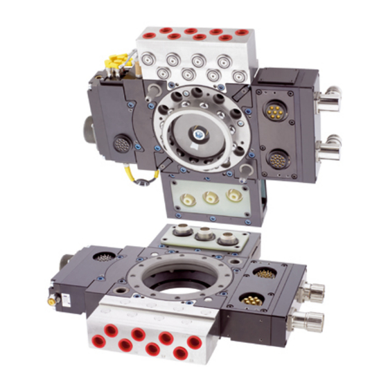
- Page 1 Original manual Assembly and operating manual SWS-L Heavy Load Change System...
- Page 2 Imprint Copyright: This manual is protected by copyright. The author is SCHUNK GmbH & Co. KG. All rights re- served. Any reproduction, processing, distribution (making available to third parties), translation or other usage - even excerpts - of the manual is especially prohibited and re- quires our written approval.
-
Page 3: Table Of Contents
8.2.2 Lock and Unlock Sensor Assembly Replacement........ 39 8.2.3 Lock/Unlock Sensor Adjustment and Replacement (Units using individual sensors) .................... 44 8.2.4 RTL Sensor Replacement ................ 46 8.2.5 Alignment Pin Replacement .............. 49 Recommended Spare Parts ................ 51 02.00 | SWS-L | Assembly and operating manual | en | 0389037... - Page 4 8.3.3 SWS-L-510.................... 51 8.3.4 SWS-L-1210..................... 51 Assembly drawings ..................... 52 8.4.1 SWS-L-210.................... 52 8.4.2 SWS-L-310.................... 54 8.4.3 SWS-L-510.................... 56 8.4.4 SWS-L-1210..................... 58 Translation of original declaration of incorporation .......... 60 Annex to Declaration of Incorporation............... 61 02.00 | SWS-L | Assembly and operating manual | en | 0389037...
-
Page 5: General
Dangers for persons! Non-observance can lead to irreversible injury and even death. CAUTION Dangers for persons! Non-observance can cause minor injuries. NOTICE Material damage! Information about avoiding material damage. 02.00 | SWS-L | Assembly and operating manual | en | 0389037... -
Page 6: Applicable Documents
A wide range of accessories are available for this product For information regarding which accessory articles can be used with the corresponding product variants, see catalog data sheet. 02.00 | SWS-L | Assembly and operating manual | en | 0389037... -
Page 7: Basic Safety Notes
• Make sure that the environment is free from splash water and vapors as well as from abrasion or processing dust. Exceptions are products that are designed especially for contaminated en- vironments. 02.00 | SWS-L | Assembly and operating manual | en | 0389037... -
Page 8: Personnel Qualification
• Wear protective gloves and safety goggles when handling haz- ardous substances. • Wear close-fitting protective clothing and also wear long hair in a hairnet when dealing with moving components. 02.00 | SWS-L | Assembly and operating manual | en | 0389037... -
Page 9: Notes On Particular Risks
Do not perform maintenance or repair on Tool Changer or • modules with power or air on. Turn off power and air before performing maintenance or re- • pair on Tool Changer or modules. 02.00 | SWS-L | Assembly and operating manual | en | 0389037... - Page 10 Damage to the Cover Plate and O-ring may result. Always attach the SWK to the Robot interface plate prior to at- • tempting any operations. 02.00 | SWS-L | Assembly and operating manual | en | 0389037...
-
Page 11: Technical Data
Meets ISO 9409- ISO 9409- Assembly 9409-1-A125 1-A200 1-200-12-M16 drawings Also supports (8) Also Supports (Position 12) 52] Fasteners on 160 (6) Fasteners on mm BC Pattern ABB ISO Pattern 02.00 | SWS-L | Assembly and operating manual | en | 0389037... - Page 12 SWK- to indicate SWK-L and L and SWA-L mating sur- SWA-L mating surfaces faces within close prox- within close proximity of imity of each other. each other. 02.00 | SWS-L | Assembly and operating manual | en | 0389037...
-
Page 13: Product Description
Flat ‘A’ is dedicated for mounting of the control/signal module along with SWK-L supply air that is provided through an air or valve adapter. Flats ‘B’, ‘C’, and ‘D’ (SWS-L-1210 Series and ‘F’) are fully interchangeable and optional modules can be arranged to suit the application or robot dress as required. - Page 14 Ball Bearing (9x) Cable Retaining Tabs Male Coupling Common Ledge Mounting Feature (3x) Internal Prox Sensors Alignment Pin (2x) Prox Sensor (Lock/Unlock) (RTL Signal) [Not visible] SWK-L 310 02.00 | SWS-L | Assembly and operating manual | en | 0389037...
- Page 15 Flats A, B, C, D, E and F Proximity Sensor (RTL Signal) Cable Retaining Tabs Proximity Sensor Lock/Unlock Air Supplied through (RTL Signal) Air/Valve Adapter Mounted to Flat A SWK-L 1210 02.00 | SWS-L | Assembly and operating manual | en | 0389037...
-
Page 16: Quick Change Adapter (Swa-L)
Flats A, B, C, and D SWA-L 210 SWA-L (Body) Alignment Pin Bushing (2x) Prox Sensor or Target (RTL) Bearing Race Prox Sensor Target (RTL) Common Ledge Mountong Feature (4x) SWA-L-310 02.00 | SWS-L | Assembly and operating manual | en | 0389037... - Page 17 Alignment Pin Bushing Common Ledge Feature For Module Mounting; Flats A, B, C, D, E and F Proximity Sensor Target (RTL) Bearing Race Proximity Sensor Target (RTL) SWA-L-1210 02.00 | SWS-L | Assembly and operating manual | en | 0389037...
-
Page 18: Optional Modules
If modules are added to a SWS-L in the field, then the SWK-L and SKA-L may have to be uninstalled to facilitate the cleat installation. 02.00 | SWS-L | Assembly and operating manual | en | 0389037... -
Page 19: Installation
Installation 5 Installation All fasteners used to mount the SWS-L to the robot and to user Tools should be tightened to a torque value as indicated below. Further- more, removable (blue) Loctite 242 must be used on these fasteners. NOTE Care should be taken to select fasteners for mounting that are not too long, such that a gap is formed at the interface. - Page 20 Minimum thread engagement of 15 mm (1.5 x fastener Ø) SWA-L (aluminum) to End-Effector Interface Plate (7075- M10–1.5 52 Nm T6 aluminum) Class 12.9 Minimum thread engagement of 15 mm (1.5 x fastener Ø) 02.00 | SWS-L | Assembly and operating manual | en | 0389037...
-
Page 21: Swk-L
SWK-L • The thickness of the interface plate must be great enough to provide the necessary thread engagement for the mounting bolts. 02.00 | SWS-L | Assembly and operating manual | en | 0389037... -
Page 22: Swa-L
• The interface plate should be designed to include bolt holes for mounting, dowel pins, and a boss that mates with SWA-L body recess for accurate positioning. • SWS-L-310: When using a locating boss, the race cover must be removed. • SWS-L-210: The locating boss height should not exceed 6.3mm. -
Page 23: Tool Stand Design
Installation 5.3 Tool Stand Design NOTICE Tool stand design is critical to proper operation of the SWS-L. Im- properly designed tool stands can cause misalignments that will cause jamming and/or excessive wear of SWS-L components. SWS-L-1210: Z-Compliance is required for the Tool Stand, in or- der to ensure that the SWK-L remains fully contacted with the SWA-L prior to issuing the Unlock command. - Page 24 * Maximum values shown. Decreasing actual values will minimize wear during coupling/ uncoupling. ** Actual allowable values may be higher in some cases but higher offsets will increase wear during coupling. 02.00 | SWS-L | Assembly and operating manual | en | 0389037...
-
Page 25: Operation
SWK-L enter the alignment holes on the Tool. The alignment pins should be relat- ively concentric with the alignment holes such that they do not rub against the edge. 02.00 | SWS-L | Assembly and operating manual | en | 0389037... - Page 26 SWS-L. SWS-L-1210: Turn the Unlatch output off. Turn the Latch output on. Air is supplied to the locking mechanism to couple the SWS-L. A sufficient delay must be programmed between the Lock com- mand being activated and reading the state of the Locked/Un- locked signals, so that the locking process is completed before checking the locked state.
-
Page 27: Fail-Safe Operation
Operation 6.2 Fail-Safe Operation In the event of air supply loss to the locking mechanism the SWS-L will not uncouple. A slight separation between the SWK-L and SWA-L occurs just after air loss, but at this point the locking balls become trapped and can- not move without air pressure being applied to the unlock port. - Page 28 SWK-L may be moved away from the SWA-L in the axial direction. SWS-L-1210: Check to verify that the RTLs are all “off” (false) after the SWK-L moves away from the SWA-L. The robot and SWK-L can now proceed to another SWA-Lfor coup- ling and subsequent operations.
-
Page 29: Integrated Sensors (Sws-L-1210)
6.4 Integrated Sensors (SWS-L-1210) The SWK-L-1210 has a total of 6 proximity sensors for detecting the Lock and Unlock state of the SWS-L. For each locking mechan- ism there is one Lock sensor and one Unlock sensor. Each sensor pair is distinguished by the corresponding locking mechanism. For example, locking mechanism #1 has “L1”... - Page 30 “R2” to give a second Tool presence signal. show the cables pertaining to the RTL sensors. The labels on the cables indic- ate which sensors the cables are connected to. 02.00 | SWS-L | Assembly and operating manual | en | 0389037...
-
Page 31: Troubleshooting
Unlock sensor is damaged Replace Unlock sensor Or Sensor Assembly as locked but Un- necessary Maintenance. lock signal Unlock sensor is out of Replace Unlock sensor or Sensor Assembly as does not read position necessary. “on” (true). 02.00 | SWS-L | Assembly and operating manual | en | 0389037... - Page 32 Check that the UNLATCH command is not being issued with the SWA-L sitting above the Tool Stand and the robot is not trying to “drop” the SWA-L into the nest. 02.00 | SWS-L | Assembly and operating manual | en | 0389037...
- Page 33 Both sensors must be “on” to get the R1 (RTL1) input “on”. Check splitter cable from R1 connector at the control module to RS1 and RS2 sensors. Re- place as needed. 02.00 | SWS-L | Assembly and operating manual | en | 0389037...
- Page 34 Check the RS3 sensor face for damage. Replace if necessary. Check cable between RS3 sensor and the R2 connector at control module for damage and replace as needed. 02.00 | SWS-L | Assembly and operating manual | en | 0389037...
-
Page 35: Maintenance And Care
Link Schmierstoffe/Schmierstellen. For this purpose, tubes of lubricant are shipped with every Tool Changer. NOTE: MobiGrease® XHP222 Special is a NLGI#2 lithium complex grease with molybdenum disulfide. 02.00 | SWS-L | Assembly and operating manual | en | 0389037... - Page 36 Clear debris from the area of the contacts using compressed air. Do not directly clean contacts as abrasion may occur and the per- formance of the contact may be compromised. 02.00 | SWS-L | Assembly and operating manual | en | 0389037...
-
Page 37: Cleaning, Lubrication, Adjustment And Replacement
Check each ball to make sure it moves freely in the male coup- Ø ling. Additional cleaning may be necessary to free up any balls that are sticking in place. 02.00 | SWS-L | Assembly and operating manual | en | 0389037... - Page 38 1. Use a clean rag to thoroughly remove any lubricant and debris from the bearing race and the bushings. 2. No re-lubrication is necessary on the SWA components. 02.00 | SWS-L | Assembly and operating manual | en | 0389037...
-
Page 39: Lock And Unlock Sensor Assembly Replacement
Attach the new assembly to the SWK-L body by tightening the Ø M3 screws to 1.36 Nm of torque. Re-attach cables and modules. Ø 02.00 | SWS-L | Assembly and operating manual | en | 0389037... - Page 40 Confirm operation of the Lock sensor by issuing the Lock com- Ø mand to lock a SWA-L to the SWK-L and then checking to see that the LED in the Lock sensor body is on. 02.00 | SWS-L | Assembly and operating manual | en | 0389037...
- Page 41 9. Confirm operation of the Lock sensor by issuing the Lock command to lock a SWA-L to the SWK-L and then checking to see that the LED in the Lock sensor body is on. 02.00 | SWS-L | Assembly and operating manual | en | 0389037...
- Page 42 Unplug the sensor cable connectors from lock and unlock sensors. Ø Remove the two M4 socket head cap screws that secure the as- Ø sembly to the SWK-L body. Slide the sensor assembly out and discard. Ø 02.00 | SWS-L | Assembly and operating manual | en | 0389037...
- Page 43 Ø Confirm operation of the Unlock sensor by issuing the Unlatch Ø command and then checking to see that the LED in the Unlock sensor body is on. 02.00 | SWS-L | Assembly and operating manual | en | 0389037...
-
Page 44: Lock/Unlock Sensor Adjustment And Replacement (Units Using Individual Sensors)
Turn proximity sensor clockwise until the LED in the sensor body Ø comes on. Turn the proximity sensor clockwise another 1/4 turn (90°). Ø Tighten jam nut to 2.26 Nm of torque. Ø 02.00 | SWS-L | Assembly and operating manual | en | 0389037... - Page 45 Turn proximity sensor clockwise until the LED in the sensor body Ø comes on. Turn the proximity sensor clockwise another 1/4 turn (90°). Ø Tighten jam nut to 2.26 Nm of torque. Ø 02.00 | SWS-L | Assembly and operating manual | en | 0389037...
-
Page 46: Rtl Sensor Replacement
Confirm operation of the new sensor by bringing a metallic ob- Ø ject into close proximity to the face of the sensor and watching for the LED in the body of the sensor to come on. 02.00 | SWS-L | Assembly and operating manual | en | 0389037... - Page 47 6. Confirm operation of the new sensor by bringing a metallic object into close proximity to the face of the sensor and watching for the LED in the body of the sensor to come on. 02.00 | SWS-L | Assembly and operating manual | en | 0389037...
- Page 48 “RS1” and “RS2” wired in series. Therefore, a metallic object has to be used at both locations in order to view the LED indicator of either sensor SWS-1210: Integrated Sensors . 02.00 | SWS-L | Assembly and operating manual | en | 0389037...
-
Page 49: Alignment Pin Replacement
Note: If for any reason the pin cannot be removed using the hex socket in the tip, it may be necessary to remove it by other means, such as Vise Grip pliers. Hex Key 3mm Hex Key - SWS-L-210 02.00 | SWS-L | Assembly and operating manual | en | 0389037... - Page 50 M8 set screw in the new alignment pin. Install the alignment pin into the bushing and screw it into Ø place. Apply 60 in-lb of torque to fully tighten it. 02.00 | SWS-L | Assembly and operating manual | en | 0389037...
-
Page 51: Recommended Spare Parts
Sensors complete Alignment Pin Alignment Pin 8.3.4 SWS-L-1210 Assembly Description SWK-L Complete SWK-L-1210, No Options SWA-L Complete SWA-L-1210, No Options Other Sensors Sensors complete Alignment Pin Alignment Pin 02.00 | SWS-L | Assembly and operating manual | en | 0389037... -
Page 52: Assembly Drawings
Maintenance and Care 8.4 Assembly drawings 8.4.1 SWS-L-210 SWS-L 210 02.00 | SWS-L | Assembly and operating manual | en | 0389037... - Page 53 Maintenance and Care SWK-L-310 SWA-L-210 02.00 | SWS-L | Assembly and operating manual | en | 0389037...
-
Page 54: Sws-L-310
Maintenance and Care 8.4.2 SWS-L-310 Assembly drawing SWS-L 310 02.00 | SWS-L | Assembly and operating manual | en | 0389037... - Page 55 Maintenance and Care SWK-L-310 SWA-L-310 02.00 | SWS-L | Assembly and operating manual | en | 0389037...
-
Page 56: Sws-L-510
Maintenance and Care 8.4.3 SWS-L-510 SWS-L 510 02.00 | SWS-L | Assembly and operating manual | en | 0389037... - Page 57 Maintenance and Care SWK-L 510 SWA-L 510 02.00 | SWS-L | Assembly and operating manual | en | 0389037...
-
Page 58: Sws-L-1210
Maintenance and Care 8.4.4 SWS-L-1210 SWS-L 1210 02.00 | SWS-L | Assembly and operating manual | en | 0389037... - Page 59 Maintenance and Care SWK-L 1210 SWA-L 1210 02.00 | SWS-L | Assembly and operating manual | en | 0389037...
-
Page 60: Translation Of Original Declaration Of Incorporation
Person authorized to compile the technical documentation: Robert Leuthner, Address: see manufacturer's address Lauffen/Neckar, November 2018 p.p. Ralf Winkler, Manager for development of gripping system components 02.00 | SWS-L | Assembly and operating manual | en | 0389037... -
Page 61: Annex To Declaration Of Incorporation
Risks due to falling or ejected objects 1.3.4 Risks due to surfaces, edges or angles 1.3.5 Risks related to combined machinery 1.3.6 Risks related to variations in operating conditions 02.00 | SWS-L | Assembly and operating manual | en | 0389037... - Page 62 Risk of slipping, tripping or falling 1.5.16 Lightning Maintenance 1.6.1 Machinery maintenance 1.6.2 Access to operating positions and servicing points 1.6.3 Isolation of energy sources 1.6.4 Operator intervention 1.6.5 Cleaning of internal parts 02.00 | SWS-L | Assembly and operating manual | en | 0389037...
- Page 63 Supplementary essential health and safety requirements for machinery intended for underground work Supplementary essential health and safety requirements for machinery presenting particular hazards due to the lifting of persons 02.00 | SWS-L | Assembly and operating manual | en | 0389037...
- Page 64 02.00 | SWS-L | Assembly and operating manual | en | 0389037...
Need help?
Do you have a question about the SWS-L and is the answer not in the manual?
Questions and answers