
Related Manuals for SCHUNK JGP 40


Summary of Contents for SCHUNK JGP 40
- Page 1 Assembly and Operating Manual JGP 2-Finger Parallel Gripper Translation of the original manual...
- Page 2 Imprint Imprint Copyright: This manual is protected by copyright. The author is SCHUNK SE & Co. KG. All rights reserved. Technical changes: We reserve the right to make alterations for the purpose of technical improvement. Document number: 389157 Version: 21.00 | 11/03/2024 | en...
-
Page 3: Table Of Contents
Table of contents Table of Contents 1 General ..................... 5 About this manual................1.1.1 Presentation of Warning Labels ............. 1.1.2 Definition of Terms ..............1.1.3 Applicable documents ..............1.1.4 Sizes..................1.1.5 Variants ................... 1.2 Warranty ................... 1.3 Scope of delivery................. 1.3.1 Accessories kit ................ - Page 4 Table of contents 5 Assembly.................... 18 5.1 Installing and connecting ..............18 5.2 Connections ..................20 5.2.1 Mechanical connection..............20 5.2.2 Pneumatic connection..............23 5.3 Mounting the sensor................24 5.3.1 Overview of sensors ..............24 5.3.2 Setting dimensions for magnetic switches ........25 5.3.3 Switch-off hysteresis for magnetic switches ........
-
Page 5: General
General 1 General 1.1 About this manual This manual contains important information for a safe and appropriate use of the product. This manual is an integral part of the product and must be kept accessible for the personnel at all times. Before starting work, the personnel must have read and understood this operating manual. -
Page 6: Definition Of Terms
Assembly and operating manuals of the accessories * Die mit Stern (*) gekennzeichneten Unterlagen können unter schunk.com/downloads heruntergeladen werden. 1.1.4 Sizes This operating manual applies to the following sizes: JGP 40 JGP 50 JGP 64 JGP 80 JGP 100 JGP 125... -
Page 7: Accessories Kit
1.3.1 Accessories kit Content of the accessory pack: 6 x Centering sleeves for mounting 2 x O-ring for hose-free direct connection 2 x screw plug for hose connection Accessory pack for JGP 40 5518410 JGP 50 5512043 JGP 64 5512044... -
Page 8: Basic Safety Notes
Use of unauthorized spare parts Using unauthorized spare parts can endanger personnel and damage the product or cause it to malfunction. Use only original spare parts or spares authorized by SCHUNK. 2.4 Gripper fingers Requirements of gripper fingers Accumulated energy can make the product unsafe and risk the danger of serious injuries and considerable material damage. -
Page 9: Ambient Conditions And Operating Conditions
Basic safety notes Execute the gripper fingers in such a way that the product reaches either the "open" or "closed" position in a de- energized state. Only change gripper fingers if no residual energy can be released. Make sure that the product and the top jaws are a sufficient size for the application. -
Page 10: Personal Protective Equipment
Basic safety notes Service personnel of Due to its technical training, knowledge and experience, service the manufacturer personnel of the manufacturer is able to perform the delegated tasks and to recognize and avoid possible dangers. 2.7 Personal protective equipment Use of personal protective equipment Personal protective equipment serves to protect staff against danger which may interfere with their health or safety at work. -
Page 11: Malfunctions
Basic safety notes Incorrect handling during transport may impair the product's safety and cause serious injuries and considerable material damage. When handling heavy weights, use lifting equipment to lift the product and transport it by appropriate means. Secure the product against falling during transportation and handling. -
Page 12: Protection During Handling And Assembly
Basic safety notes 2.12.1 Protection during handling and assembly Incorrect handling and assembly Incorrect handling and assembly may impair the product's safety and cause serious injuries and considerable material damage. Have all work carried out by appropriately qualified personnel. For all work, secure the product against accidental operation. Observe the relevant accident prevention rules. -
Page 13: Protection Against Electric Shock
Basic safety notes fence must be rigid enough to withstand the maximum possible movement energy. EMERGENCY STOP switches must be easily and quickly accessible. Before starting up the machine or automated system, check that the EMERGENCY STOP system is working. Prevent operation of the machine if this protective equipment does not function correctly. - Page 14 Basic safety notes WARNING Risk of injury from sharp edges and corners! Sharp edges and corners can cause cuts. Use suitable protective equipment. WARNING Risk of injury due to unexpected movements! If the power supply is switched on or residual energy remains in the system, components can move unexpectedly and cause serious injuries.
- Page 15 Secure the end positions of the product with SCHUNK SDV-P pressure maintenance valves. 21.00 | JGP | Assembly and Operating Manual | en | 389157...
-
Page 16: Technical Data
* For use in dirty ambient conditions (e.g. sprayed water, vapors, abrasion or processing dust) SCHUNK offers corresponding product options as standard. SCHUNK also offers customized solutions for special applications in dirty ambient conditions. 21.00 | JGP | Assembly and Operating Manual | en | 389157... -
Page 17: Design And Description
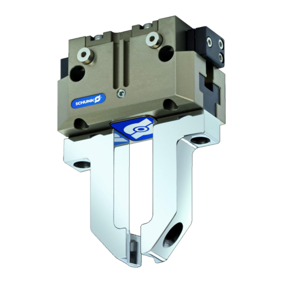
Design and description 4 Design and description 4.1 Design 2-Finger Parallel Gripper Housing Air purge connection Compressed air main connection Base jaw 4.2 Description Universal 2-finger parallel gripper with T-slot guidance 21.00 | JGP | Assembly and Operating Manual | en | 389157... -
Page 18: Assembly
Assembly 5 Assembly 5.1 Installing and connecting WARNING Risk of injury due to unexpected movements! If the power supply is switched on or residual energy remains in the system, components can move unexpectedly and cause serious injuries. Before starting any work on the product: Switch off the power supply and secure against restarting. - Page 19 Assembly Connect the product via the hose-free direct connection. ð Use O-rings from the accessory pack. ð Seal main air connections which are not required with locking screws. OR: Connect compressed air lines to the main air connections "A" and "B". ð Screw in air connections (plug connections). OR: Screw on throttle valve in order to be able to perform sufficient throttling and/or damping.
-
Page 20: Connections
Assembly 5.2 Connections 5.2.1 Mechanical connection Evenness of the The values apply to the whole mounting surface to which the mounting surface product is mounted. Edge length Permissible unevenness < 100 < 0.02 > 100 < 0.05 Tab.: Requirements for evenness of the mounting surface (Dimensions in mm) Connections at the base jaws Connections at the base jaws... - Page 21 Assembly Connections at the housing Item Mounting Side A Mounting screw Max. depth of engagement from locating surface [mm] for variants IS/AS Centering sleeve Ø5 Ø6 Ø8 Ø8 Ø10 Ø12 Fitting bore for – – Ø4 Ø4 Ø5 Ø6 centering pin [mm] Side B Mounting screw M2.5...
- Page 22 Assembly Item Mounting Side A Mounting screw Max. depth of engagement 25.5 from locating surface [mm] for variants IS/AS Centering sleeve Ø12 Ø14 Ø16 Ø22 Fitting bore for centering Ø6 – – Ø10 pin [mm] Side B Mounting screw Mounting screw according DIN EN ISO 4762 to standard Centering sleeve...
-
Page 23: Pneumatic Connection
Assembly 5.2.2 Pneumatic connection Air connections Main connections (Hose connection) (A = open, B = close) Hose-free direct connection at the base (a = open, b = close) Hose-free direct connection Air purge connection Hose-free direct connection O-ring Attachment Product Item R1/8 R1/8... -
Page 24: Mounting The Sensor
– The assembly and operating manual and catalog datasheet are included in the scope of delivery for the sensors and are available at schunk.com. Information on handling sensors is available at schunk.com or from SCHUNK contact persons. 5.3.1 Overview of sensors... -
Page 25: Setting Dimensions For Magnetic Switches
The magnetic switch MMS 22-PI1 can be adjusted and taught in two ways. "Standard mode" allows for quick installation on the T-nut preset by SCHUNK in the groove or the defined setting dimension "l1." In "Optimal Mode", the sensor identifies the optimal position in the groove itself. -
Page 26: Switch-Off Hysteresis For Magnetic Switches
Assembly 5.3.3 Switch-off hysteresis for magnetic switches Sensors MMS 22, MMS 22-PI1, MMS 22-PI2 and MMS-P 22 The smallest detectable difference in stroke is defined in the following table: For products with X mm Min. query range per jaw/ nominal stroke per jaw min. -
Page 27: Mounting Magnetic Switch Mms 22
Assembly 5.3.5 Mounting magnetic switch MMS 22 CAUTION Risk of damage to the sensor during assembly! Observe the maximal tightening torque. Positioning the magnetic switches Position "Gripper open" or "Part gripped (I.D. gripping)" Bring product in the position to be set. If necessary remove T-nut (3). -
Page 28: Mounting Programmable Magnetic Switch Mms 22-Pi1
The magnetic switch MMS 22-PI1 can be adjusted and taught in two ways. "Standard mode" allows for quick installation on the T-nut preset by SCHUNK in the groove or the defined setting dimension "l1." In "Optimal Mode", the sensor identifies the optimal position in the groove itself. - Page 29 Assembly Alternatively for size 40 – 160, except size 50: Setting the sensor in "Standard mode" Turn the sensor 1 (1) into the groove (2). OR: Slide the sensor 1 (1) into the groove (2) until the sensor 1 (1) stops at the T-nut (3). Secure the sensor 1 (1) using the set-screw (4).
-
Page 30: Mounting Programmable Magnetic Switch Mms 22-Pi2
Assembly 5.3.7 Mounting programmable magnetic switch MMS 22-PI2 CAUTION Risk of damage to the sensor during assembly! Observe the maximal tightening torque. NOTE If there is no T-nut available, slide the sensor according to dimension I1 into the groove (2), } 5.3.2 [/ 25]. -
Page 31: Mounting Programmable Magnetic Switch Mms-P 22
Assembly 5.3.8 Mounting programmable magnetic switch MMS-P 22 CAUTION Risk of damage to the sensor during assembly! Observe the maximal tightening torque. NOTE If there is no T-nut available, slide the sensor according to dimension I1 into the groove (2), [/ 25]. -
Page 32: Mounting The Mms 22-Iol Magnetic Switch
Assembly 5.3.9 Mounting the MMS 22-IOL magnetic switch CAUTION Risk of damage to the sensor during assembly! Observe the maximal tightening torque. NOTE If there is no T-nut available, slide the sensor according to dimension I1 into the groove (2), see following table. Turn the sensor (1) into the groove (2). -
Page 33: Mounting Inductive Proximity Switch In 80
Assembly 5.3.10 Mounting inductive proximity switch IN 80 CAUTION Blockade of the gripper after setting or replacing of the switching cam! The switching cam can be tilt in the guide, if it was not fixed exactly in the base jaw. Apply the switching cam in the direction of the base jaw, so that the cam does not contact the housing of the gripper. - Page 34 Assembly Position "Gripper closed" or "Part gripped (O.D. gripping)" Slide the sensor 2 (1) into the bracket (2) until it stops. Tighten the screw (3) on the bracket (2). Tightening torque: 0.2 Nm Close gripper or grip part. Unfasten the screw (4). Turn the screw (5) to adjust the position of the control cam (6).
-
Page 35: Mounting Reed Switch Rms 80
Assembly 5.3.11 Mounting reed switch RMS 80 CAUTION Blockade of the gripper after setting or replacing of the switching cam! The switching cam can be tilt in the guide, if it was not fixed exactly in the base jaw. Apply the switching cam in the direction of the base jaw, so that the cam does not contact the housing of the gripper. - Page 36 Assembly Position "Gripper closed" or "Part gripped (O.D. gripping)" Slide the sensor 2 (1) into the bracket (2) until it stops. Tighten the screw (3) on the bracket (2). Tightening torque: 0.2 Nm Close gripper or grip part. Unfasten the screw (4). Turn the screw (5) to adjust the position of the control cam (6).
-
Page 37: Mounting Flexible Position Sensor Fps
Assembly 5.3.12 Mounting flexible position sensor FPS The flexible position sensor FPS consists of a torque sensor system controller and the sensor FPS-S M8. To be able to mount the sensor, the gripper has to be retrofitted with a special mounting kit. CAUTION Risk of damage to the sensor during assembly! Observe the maximal tightening torque. -
Page 38: Mounting Analog Position Sensor Aps-M1
ð Make sure that there is no adhesive on the bottom of the control cam (6), which comes into contact with the sensor. ð SCHUNK recommends the adhesive Loctite 290 or 638. Slide control cam (6) out of the mounting kit front into the base jaw. - Page 39 Assembly Slide the sensor (1) to the stop into the bracket (2). Tighten the screw (3) on the bracket (2). Tightening torque: 0.2 Nm Adjust sensor (1), see assembly and operating manual of the sensor. 21.00 | JGP | Assembly and Operating Manual | en | 389157...
-
Page 40: Mounting Analog Position Sensor Aps-Z80
With O.D. gripping the "Gripper closed" position and with I.D. gripping the "Gripper opened" position cannot be queried. Should you have questions, do not hesitate to contact SCHUNK. Actual signal Optimum signal Stroke [mm] Analog signal on O.D. - Page 41 ð SCHUNK recommends the adhesive Loctite 290 or 638. Slide control cam (6) into the base jaw to the stop. ð Ensure that the higher front side of the control cam (6) is pointing outwards.
-
Page 42: Mounting The Radio System Rss-R1/T2
Assembly 5.3.15 Mounting the radio system RSS-R1/T2 The radio system RSS-R1/T2 can be used with the following sensors: Reed switch RMS 80 Assembly Install the sensor, [/ 35]. } 5.3.11 Adjust the sensor, see the assembly and operating manual for the sensor. Connect the radio system, see the assembly and operating manual for the radio system. -
Page 43: Troubleshooting
Proximity switch defective or set incorrect. Readjust or change sensor. Unused air connections open. Close unused air connections. Component part defective. Replace component or send it to SCHUNK for repair. 6.2 Product is not executing the complete stroke Possible cause Corrective action Dirt deposits between cover and piston. -
Page 44: Product Does Not Achieve The Opening And Closing Times
Corrective action Pressure drops below minimum. Check air supply. } 3 [/ 16] Component part defective. Replace component or send it to SCHUNK for repair. 6.5 Product does not achieve the opening and closing times Possible cause Corrective action Compressed air lines are not installed If present: Open the flow control couplings on optimally. -
Page 45: Maintenance
Maintenance 7 Maintenance 7.1 Notes Original spare parts Use only original spare parts of SCHUNK when replacing spare and wear parts. Replacement of the housing and base jaws The base jaws and the guides in the housing are matched to each other. -
Page 46: Lubricants/Lubrication Points (Basic Lubrication)
Seals and sealing surfaces SCHUNK grease 1 Cylinder surfaces SCHUNK grease 1 Details on the SCHUNK lubricant designations are available at schunk.com/lubricants The product contains food-compliant lubricants as standard. The requirements of standard EN 1672-2:2020 are not fully met. NOTE Change contaminated food-compliant lubricant. -
Page 47: Disassembly And Assembly
Maintenance 7.4 Disassembly and assembly 7.4.1 Disassemble the product 7.4.1.1 Variant without maintenance of gripping force Position of the item numbers, [/ 53]. } 7.5 Remove the compressed air hoses. Remove the cover (5). Mark the installation position of the piston (3) and the base jaws (2) in the housing (1). - Page 48 Maintenance WARNING Danger of injury due to spring forces! The cylinder piston is under spring tension. Carefully disassemble the product. Clamp the gripper carefully between the base jaws (2) and the cylinder piston (60). Unscrew the screws (45). Carefully unclamp the vise until the spring force is released Remove the cylinder piston (60) from the housing (1).
-
Page 49: Assembling The Product
Maintenance Remove the cover (9) and the compression spring (25). Unscrew screw (40) and remove cylinder piston (60) from the housing (1). Press the piston (3) upward out of the housing (1). Pull the base jaws (2) out of the housing (1). 7.4.2 Assembling the product 7.4.2.1 Notes for assembly Assembly takes place in the opposite order to disassembly. - Page 50 Maintenance Carefully put device (100) over the cylinder piston (60) and attach to the housing (50) using the screws (101). Screw in screw (45) and tighten with the appropriate tightening torque, [/ 53]. } 7.4.2.4 Remove the device (100) and continue to assemble the gripper in the opposite order to disassembly, [/ 53].
- Page 51 Maintenance 7.4.2.3 Assembly device cylinder piston with gripping force maintenance 7.4.2.3.1 Sizes 40 - 100 D H8 B - B 0.02 0.02 l 1 ± 0.02 Ø 15 A - A Tab.: Cylinder piston assembly device – dimensions in mm 22.5 14.5 Screw (DIN EN ISO 4762) Item 101 M3 x 20...
- Page 52 Maintenance 7.4.2.3.2 Sizes 160-300 C – C D – D Assembly device for maintaining the gripping force Tab.: Cylinder piston assembly device - dimensions in mm Type JGP 160 90.5 57.5 JGP 200 JGP 240 13.5 JGP 300 114.3 17.5 Tab.: Cylinder piston assembly device - dimensions in mm Size JGP 160...
-
Page 53: Assembly Drawing
7.4.2.4 Tightening torque for screws Position of the item numbers, } 7.5 [/ 53] Tab.: Screw tightening torques Item JGP 40 JGP 50 JGP 64 JGP 80 JGP JGP240 JGP 2.2 Nm 2.2 Nm 5.9 Nm 10 Nm 10 Nm 24 Nm 47 Nm... - Page 54 Maintenance Assembly of O.D. gripping (OD) / I.D. gripping (ID)/ without gripping force maintenance Wearing part, replace during maintenance. Included in the seal kit. Seal kit can only be ordered completely. Positions are adapted to each other and can not be replaced by the customer. for sizes 100 - 300 Item.
-
Page 55: Translation Of The Original Declaration Of Incorporation
8 Translation of the original declaration of incorporation in terms of the Directive 2006/42/EG, Annex II, Part 1 Section B. Manufacturer/ SCHUNK SE & Co. KG Distributor Toolholding and Workholding | Gripping Technology | Automation Technology Bahnhofstr. 106 - 134... -
Page 56: Ukca Declaration Of Incorporation
UKCA declaration of incorporation 9 UKCA declaration of incorporation in accordance with the Supply of Machinery (Safety) Regulations 2008. Manufacturer/ SCHUNK Intec Limited Distributor Clamping and gripping technology 3 Drakes Mews, Crownhill MK8 0ER Milton Keynes We hereby declare that on the date of the declaration the following partly completed machine complied with all basic safety and health regulations found in the "Supply of Machinery (Safety) Regulations 2008". -
Page 57: Information On The Rohs Directive, Reach Regulation And Substances Of Very High Concern (Svhc)
"on the restriction of the use of certain hazardous substances in electrical and electronic equipment (RoHS)", or fulfill their intended function only as part of one. Therefore products from SCHUNK do not fall within the scope of the directive at this time. REACH Regulation Products from SCHUNK fully comply with the regulations of Regulation (EC) No. 1907/2006... - Page 58 21.00 | JGP | Assembly and Operating Manual | en | 389157...
- Page 59 21.00 | JGP | Assembly and Operating Manual | en | 389157...
- Page 60 SCHUNK SE & Co. KG Toolholding and Workholding | Gripping Technology | Automation Technology Bahnhofstr. 106 - 134 D-74348 Lauffen/Neckar Tel. +49-7133-103-0 info@de.schunk.com schunk.com Folgen Sie uns I Follow us Wir drucken nachhaltig I We print sustainable...
Need help?
Do you have a question about the JGP 40 and is the answer not in the manual?
Questions and answers