
Related Manuals for ClimateMaster AVB32V02R


Summary of Contents for ClimateMaster AVB32V02R
- Page 1 AVB32V02R CM300 series Programmable Digital Thermostat Residential 7 Day Programmable Up to 3-heat & 2-cool • with Wi-Fi Local API Owner’s Manual & Installation Instructions...
- Page 2 CAUTION Follow the Installation Instructions before proceeding. Set the thermostat mode to “OFF” prior to changing settings in setup or restoring Factory Defaults. FCC Compliance Statement This equipment has been tested and found to comply with the limits for a Class B digital device, pursuant to part 15 of the FCC Rules.
- Page 3 Under Industry Canada regulations, this radio transmitter may only operate using an antenna of a type and maximum (or lesser) gain approved for the transmitter by Industry Canada. To reduce potential radio interference to other users, the antenna type and its gain should be so chosen that the equivalent isotropically radiated power (e.i.r.p.) is not more than that necessary for successful communication.
-
Page 4: Table Of Contents
Table of Contents Installation Instructions ....................1 Wire Connections ......................2 Thermostat Backplate .....................3 Dip Switch Settings and Wiring..................4 Connect to Wi-Fi.......................9 Front Panel & Display ....................12 Basic Operation......................15 User Setup Clock ........................18 Enable programmability...................19 Backlight/Nighttime dimmer ................19 Installer Setup Display Units F/C ....................20 Deadbands, timers ..................20, 22 Setpoint Limiting ....................21 Available Modes ....................21... - Page 5 Glossary of Terms Auto-Changeover: A mode in which the thermostat will turn on the heating or cooling based on room temperature demand. Cool Setpoint: The warmest temperature that the space should rise to before cooling is turned on (without regard to deadband). Deadband: The number of degrees the thermostat will wait, once a setpoint has been reached, before energizing heating or cooling.
-
Page 6: Installation Instructions
Installation Instructions Remove and Replace the old thermostat To install the thermostat properly, please follow these step by step instructions. If you are unsure about any of these steps, call a qualified technician for assistance. • Installation tools: Small flat blade screwdriver, Phillips screwdriver, wire cutters and wire strippers. -
Page 7: Wire Connections
Installation Instructions Wire Connections If the terminal designations on your old thermostat do not match those on the new thermostat, refer to the chart below or the wiring diagrams that follow. Install on the new Wire from the old thermostat Function thermostat terminal Function... -
Page 8: Thermostat Backplate
Installation Instructions The Thermostat Backplate To remove the thermostat backplate: Gently separate the display from the base by pulling from the center. IMPORTANT: This thermostat requires both R (24 VAC Return) and C (24 VAC Common) wires be connected to the backplate terminals to operate properly. -
Page 9: Dip Switch Settings And Wiring
Installation Instructions Check Dip Switch Ensure which switch is correct for your system. Dip switches are located on the GAS/EL back of the thermostat. ELEC GAS/EL ELEC This switch (GAS/ELEC or HP) configures the GAS/EL GAS/EL thermostat to control a conventional gas/electric system or a heat pump. - Page 10 Installation Instructions 1 Stage Heat, 1 stage Cool GAS/EL ELEC Dip Switch Settings GAS/EL ELEC Thermostat HVAC Equipment Condensate Switch (optional) Note: Set DRY CONTACT USE (setup step #26) to CONDENSATE...
- Page 11 Installation Instructions 2 Stage Heat, 2 Stage Cool with wired remote sensor GAS/EL ELEC Dip Switch Settings GAS/EL ELEC Thermostat HVAC Equipment 10KNTC Remote Sensor (optional)
- Page 12 Installation Instructions Single Stage Heat Pump with AUX Heat GAS/EL ELEC Dip Switch Settings GAS/EL ELEC Thermostat Single Stage Unit, CXM SCALE 1 : 1 Note: Do not clip jumper JW1 on CXM board...
- Page 13 Installation Instructions Dual Stage Heat Pump with AUX Heat and ClimaDry GAS/EL ELEC Dip Switch Settings GAS/EL ELEC Thermostat Two Stage Unit, DXM2 O/W2 Note: If using the integral condensate overflow sensing in the heatpump, SCALE 1 : 1 an overflow condition generates a FAULT signal which halts equipment operation.
-
Page 14: Connect To Wi-Fi
Skyport account setup). 3. A 6-digit code obtained from the thermostat is successfully entered into a Skyport account. 4. Successfully download and install the ClimateMaster Skyport app on your mobile device(s). Your thermostat operates on the 2.4 Ghz, Wi-Fi b/g/n band. - Page 15 Connect to Wi-Fi Overview Wi-Fi Setup The ClimateMaster Configurator App is needed to configure the Wi-Fi Settings of this thermostat • Download the ClimateMaster Configurator App from your mobile device’s App Store. • Open the ClimateMaster Configurator App - Choose the Mini thermostat picture.
- Page 16 Connect to Wi-Fi Overview Join a Thermostat to Skyport If the thermostat is connected to the local Wi-Fi access point but not yet joined to an existing Skyport account, you may join the thermostat to the account by doing the following: 1.
-
Page 17: Front Panel & Display
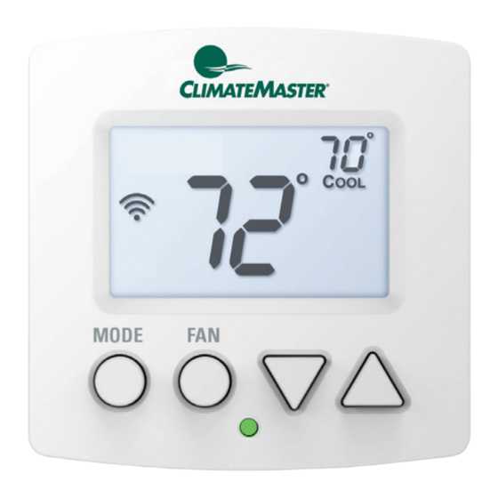
Front Panel 1 Backlit Display 2 Up/Warmer, Down/Cooler Buttons 3 MODE Button 4 FAN Button 5 Heat or Cool Indicator Heat = Red, Cool = Green... - Page 18 Display Mode Indicators Selects the operational mode of the equipment. HEAT - Indicates the heating mode. COOL - Indicates the cooling mode. AUTO - Indicates the system will automatically changeover between heat and cool modes as the temperature varies. OFF - Indicates heating and cooling are turned off. Clock with Day of the Week Indicates the current time and day.
- Page 19 Display 5 Morning, Day, Evening & Night icons Indicates the part of the time period program. 6 Setup icon Indicates the thermostat is in the setup mode. 7 Fan icon When only the FAN icon is displayed, the fan is always on.
-
Page 20: Basic Operation
Basic Operation Selecting Your Desired Temperature (adjusting the setpoints) Auto-Changeover Mode Pressing the WARMER or COOLER buttons in Auto mode will adjust both the heat and cool setpoints simultaneously. To adjust the heat and cool setpoints individually, choose HEAT mode to adjust the heat setpoint, and COOL mode to adjust the cool setpoint, then return to AUTO mode. - Page 21 Basic Operation Selecting Your Desired Humidity This thermostat is a perfect solution for reducing space humidity when using Climate Master two stage system with ClimaDry. To control dehu- midification, be sure to set AUX USE (Setup Step 29) to ‘dehumidifier’. Conversely, you can control a humidifier by setting AUX USE (Setup Step 29) to humidifier’.
-
Page 22: User Setup
User Setup TO ENTER MENUS BUTTON PRESS Setup Steps MODE & FAN for 5 seconds Table for button Time Schedule MODE & UP for 2 seconds presses that are Emergency Heat UP & FAN for 2 seconds required for Lockout Buttons MODE, UP &... -
Page 23: Clock
User Setup Setting the Clock and Day (setup step 1 & 2) When your thermostat is connected to Skyport Cloud Services, the time and day of the week are controlled by Skyport. There is no local adjustment, Skyport also adjusts the time for Daylight Savings Time as well. To set the time and day when not connected to Skyport;... -
Page 24: Enable Programmability
User Setup: Backlight Operation Prog (Setup Step 4) Adjust to ON or OFF to allow the thermostat to be 7 day programmable Backlight (Setup Steps 5-8) Backlight (Setup Step 5) OFF - Backlight turns on only with a button press and turns off after 8 seconds. -
Page 25: Display Units F/C
User Setup: Fan Operation Display Fahrenheit or Celsius (Setup Step 9) This feature allows the thermostat to display temperature in Fahrenheit or Celsius. Minimum Heat/Cool Spread (Setup Step 10) This feature allows the user to set the minimum gap between Heat and Cool setpoints in AUTO mode. -
Page 26: Setpoint Limiting
User Setup: Setpoints Setpoint Limits (Setup Steps 11-13) When this feature is set to ON, the Heat and Cool Setpoints may be restricted to preset levels in Setup Steps 12 and 13. Maximum Heat Setpoint (Setup Step 12) Minimum Cool Setpoint (Setup Step 13) Available Modes (Setup Step 14) This setup step may restrict the use of this thermostat to: Heat only or, Cool only, or Heat... - Page 27 User Setup Deadband Settings (Setup Steps 15-18) The Deadband is the number of degrees or minutes that the thermostat waits before it initiates the stages of heating or cooling. 1st Stage Deadband (Setup Step 15) Specifies the temperature difference between the room temperature and the desired setpoint before the first stage of heating or cooling is allowed to turn on.
-
Page 28: Fan Off Delay
User Setup Fan Off Delay (Setup Step 19) This feature allows the user to increase the cooling or electric strip heating efficiency of the system. The thermostat may be programmed to continue running the fan after a call for cooling or electric strip heating has been satisfied. -
Page 29: Filter Runtimes, Alerts
User Setup: Service Filter These setup steps allow the user to monitor FAN runtimes and program service alerts. Service alerts appear on the display. If the thermostat is joined to a Skyport account, then the user may be alerted by Skyport Cloud Services when to change the filter. -
Page 30: Comfort Recovery
User Setup Comfort Recovery (Setup Step 24) With Comfort Recovery on, the thermostat will attempt to reach the Morning setpoint temperature at the exact time programmed into the thermostat. Comfort Recovery, only works when the thermostat enters the Morning period from the Night Period. For example, if the Night Period is set for 11pm at 65°F heating and 85°F cooling, and the Morning Period is set for 6am at 72°F heating and 75°F cooling,... -
Page 31: Dry Contact
User Setup Dry Contact Operation Dry Contact Polarity (Setup Step 25) Open (Normally Open) - The dry contact is open until the connected device closes the circuit. ‘Idle’ ‘Active’ ‘Idle’ ‘Active’ Closed (Normally Closed) - The dry contact is closed until the connected device opens the circuit. ’... -
Page 32: Remote Sensor
User Setup FDD - If selected and the dry contact is active, “EQUIP FAULT” appears on the display. The equipment is still allowed to run unless the signal is due to an actual internal equipment fault or condensate sensor. Wired Sensor Type (Setup Step 27) RETURN, OUTDOOR, SUPPLY = the sensor temperature is reported to Skyport to monitor only... -
Page 33: Dehumidify/Humidify
User Setup Aux Polarity (Setup Step 30) Select NORMAL OPENED or NORMAL CLOSED to specify the output voltage on D / H terminal when there is no dehumidify/humidify call. Cool to Dehum (Setup Step 31) For use with non-ClimaDry equipment. Set to ON to possibly allow cooling to turn on exclusively to lower the room humidity. - Page 34 User Setup Dehum with Cool Only or Hum with Heat Only (Setup Step 34) Depending on how AUX USE (Setup Step 29) is configured, this step is used to control whether the equipment must be running before the D / H output can turn on. Humidifying for example, you might not want to turn on the humidifier unless the thermostat is calling for heat.
-
Page 35: Skyport Enable
User Setup Skyport (Setup Step 35) If set to ON, the thermostat may communicate and receive data from the Skyport Cloud Services. API (Setup Step 36) Turning on the local API allows 3rd party software to interface with the thermostat such as a home automation system. -
Page 36: Locking/Unlocking The Keypad
User Setup Locking/Unlocking the Keypad To prevent unauthorized use of the thermostat, the front panel buttons may be disabled. To disable, or ‘lock’ the keypad, press and hold the MODE button. While holding the MODE button, press the WARMER and COOLER buttons together, for two seconds. -
Page 37: Programming A Daily Schedule
Programming a Daily Schedule Programming a Daily Schedule - To enter MODE Time Period Programming screens, Press and hold MODE and UP until the scrolling prompt appears. Select Day of Week to program - Press the WARMER or COOLER buttons to choose the day of the week. Press MODE to advance to the next step. - Page 38 Programming a Daily Schedule Continued Select Morning Cool Setpoint - Press the WARMER or COOLER buttons to adjust the cool setpoint desired. This step will appear if Cool or Auto Mode was selected in the step where the Morning mode is specified. Press MODE to advance to the next step. Select Morning Heat Setpoint - Press the WARMER or COOLER buttons to adjust the heat setpoint desired.
-
Page 39: About Advanced Features & Operation
About Advanced Features & Operation DEADBAND OPERATION - Controls heat pump up to three Heat and two Cool stages and heat/cool up to two heat and two cool stages. The 1st Stage of heat or cool is turned on when: (A) The temperature spread from the setpoint is equal to or greater than: the setpoint plus the 1st stage deadband (Setup Step 15). - Page 40 About Advanced Features & Operation Heating Cooling Deadband Deadband Deadband Deadband Deadband db 3 db 2 db 1 db 1 db 2 (non-adj. 2˚) (adj. 0-10˚) (adj. 1-6˚ ) (adj. 1-6˚ ) (adj. 0-10˚ ) 3rd Stage 2nd Stage 1st Stage 1st Stage 2nd Stage Heat...
- Page 41 About Advanced Features & Operation Calibration Under normal circumstances it will not be necessary to adjust the calibration of the temperature sensor. If calibration is required, please contact a trained HVAC technician to correctly perform the following procedure. MODE Place the thermostat in the OFF mode. Press and hold the MODE button.
- Page 42 About Advanced Features & Operation Factory Defaults If, for any reason, you desire to return all the stored settings back to the factory default settings, follow the instructions below. WARNING: This will reset all Time Period and Advanced Programming to the default settings. Any information entered prior to this reset will be permanently lost.
- Page 43 About Advanced Features & Operation (Continued) You now have the option of restoring the factory settings to just Wi-Fi (Wi-Fi), or just the thermostat (STAT), or both the thermostat and Wi-Fi (ALL). C. Select one of the above options using the Up or Down buttons.
-
Page 44: Advanced Setup Table
Advanced Setup Table FD = Factory Default Setting Step# Description Pg# Range CLOCK 12A - 12A WEEKDAY Monday - Sunday Monday SHOW CLOCK On, Off PROG On, Off BACKLIGHT On, Off NIGHTLT On, Off NIGHTLT START 12A - 12A 8:00P NIGHTLT STOP 12A - 12A 6:00A... - Page 45 Advanced Setup Table FD = Factory Default Setting Step# Description Pg# Range DEHUM OVER-COOL 1 - 20 degrees FAN WITH DEHUM / FAN WITH HUM On, Off DEHUM WITH COOL ONLY / On, Off HUM WITH HEAT ONLY SKYPORT On, Off On, Off TIME API On, Off...
- Page 46 Warranty One-Year Warranty - This Product is warranted to be free from defects in material and workmanship. If it appears within one year from the date of original installation, whether or not actual use begins on that date, that the product does not meet this warranty, a new or remanufactured part, at the manufacturer’s sole option to replace any defective part, will be provided without charge for the part itself provided the defective part is returned to the distributor through a qualified servicing dealer.
- Page 47 P/N 88-1356 rev. 3 01/10/20...
Need help?
Do you have a question about the AVB32V02R and is the answer not in the manual?
Questions and answers