Table of Contents
Advertisement
Quick Links
Advertisement
Table of Contents

Related Manuals for ClimateMaster ATA32V01


Summary of Contents for ClimateMaster ATA32V01
- Page 1 ATA32V01 Controls Single or Dual Stage Geothermal Heatpump Systems with strip heat Up to 3-heat & 2-cool • Dual Setpoint • Large, Easy To Read Display • Thermoglow™ Backlight • Auto-Changeover • No batteries required • Locking Keypad Owner’s Manual & Installation Instructions...
-
Page 2: Table Of Contents
Basic Operation ...............8 Advanced Setup ..............9 Advanced Setup Table ..........12 About Advanced Features & Operation ....13 Warranty ................19 CAUTION IMPORTANT Follow Installation Instructions carefully. Disconnect Power to your heatpump before removing the old thermostat and installing the new thermostat. P/N ATA32V01 © Copyright 2019, All Rights Reserved... -
Page 3: Front Panel
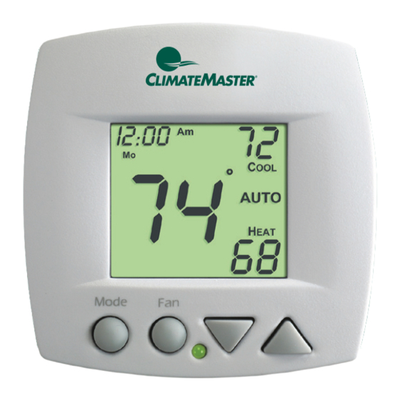
Front Panel Liquid Crystal Display with Thermoglow™ Up/Down Buttons Mode Button Fan Button Heat or Cool Indicator Red = Heat, Green = Cool... -
Page 4: Display
Display Setup SuMoTuWeThFrSa Locked Fan On Mode Indicators - Page 7 Selects the operational mode of the equipment. HEAT - Indicates the heating mode. COOL - Indicates the air conditioning mode. AUTO - Indicates the system will automatically changeover between heat and cool modes as the temperature varies. - Page 5 Display Setup SuMoTuWeThFrSa Locked Fan On Setup icon - Pages 9-12 Indicates the thermostat is in the setup mode. Fan On icon - Page 8 Indicates constant, continuous fan operation. When Fan On is not lit - indicates the fan will only operate when necessary to heat or to cool.
-
Page 6: Wiring Diagrams
Wiring Diagrams Single Stage Unit, CXM R G Y1 W O Y2 C figure 1 Two Stage Unit, DXM R G Y1 W O Y2 C O/W2 figure 2... -
Page 7: Quick Start Setting The Clock
Quick Start Setting the Clock How to Change Settings in the Setup Screens To enter the setup screens, press the MODE button, and simultaneously press FAN button for 2 seconds. Release the buttons when you see “Setup” on the display. Use the WARMER or COOLER buttons to adjust the value of your selection. -
Page 8: Selecting The Heat Or Cool Mode
Quick Start Selecting the Heat or Cool Mode Select Mode by Pressing the MODE Button MODE Heating Only The HEAT setting indicates the temperature the room has to reach before the furnace will turn on to heat the room. Cooling Only The COOL setting indicates the temperature the room has to reach before the air conditioner will turn on to cool the room. -
Page 9: Basic Operation
Basic Operation Selecting Your Desired Temperature (adjusting the setpoints) AUTO MODE Pressing the UP or DOWN buttons in Auto will adjust both the heat and cool set temperatures simultaneously. HEAT OR COOL MODE Pressing the UP or DOWN buttons in Heat OR Cool mode will adjust only the heat OR cool set temperature. -
Page 10: Advanced Setup
Advanced Setup MODE Press the MODE button. While holding MODE, press the FAN button for 10 seconds to enter setup screens. Pressing the FAN button while holding in the MODE button for 2 seconds will bring up the Clock Set screen on the display. Continuing to hold both buttons in for an additional 8 seconds will allow access to the Advanced Setup Steps that follow the Clock Set steps. - Page 11 Advanced Setup Adjust the deadband for the 1st stage (1˚ - 6˚) by pressing the UP and DOWN Setup buttons. Adjust the minimum difference between cooling & heating setpoints by pressing Setup the UP and DOWN buttons.
- Page 12 Advanced Setup Setup Select backlight operation: ON - Light continuously OFF - Light for 8 seconds after a button press Setup Select thermostat operation in degrees Fahrenheit or Celsius. After programming is complete, press the MODE and FAN buttons at the same time for two seconds to leave the Setup screens.
-
Page 13: Advanced Setup Table
Advanced Setup Table FD = Factory Default Setting Step# Description Pg# Range Set Time of Day 24 hour 12:00am Set Day of Week Monday - Sunday Deadband/Temp. Swing 1st Stage 1˚ - 6˚ 2˚ Minimum Heat/Cool Differential 0˚ - 6˚ 2˚... -
Page 14: About Advanced Features & Operation
About Advanced Features & Operation CALIBRATION - Under normal circumstances it will not be necessary to adjust the calibration of the temperature sensor. If calibration is required, please contact a trained HVAC technician to correctly perform the following procedure. Place the thermostat in the OFF mode by pressing the MODE button. - Page 15 About Advanced Features & Operation DEADBAND OPERATION - Controls up to three Heat and two Cool stages (please see the diagram on the next page). The 1st Stage of heat or cool is turned on when: (A) The temperature spread from the setpoint is equal to or greater than: the setpoint plus the 1st stage deadband (step #3, page 10).
- Page 16 About Advanced Features & Operation Heating Cooling Deadband Deadband Deadband Deadband Deadband db 3 db 2 db 1 db 1 db 2 (non-adj. 2˚) (non-adj. 2˚) (adj. 1-6˚ ) (adj. 1-6˚ ) (non-adj. 2˚ ) 3rd Stage 2nd Stage 1st Stage 1st Stage 2nd Stage Heat...
- Page 17 About Advanced Features & Operation FACTORY DEFAULTS - If, for any reason, you desire to return all the stored settings back to the factory default settings, follow the instructions below. Place the thermostat in the OFF mode by pressing the MODE button. MODE Press and hold the MODE button.
- Page 18 About Advanced Features & Operation WARNING: This will reset all Advanced Programming to the default set- tings. Any information entered prior to this reset will be permanently lost. HEAT/COOL DIFFERENTIAL - The Heat and Cool setpoints will not be allowed to come any closer to each other than the value set in Advanced Setup step #4, on page 10.
- Page 19 About Advanced Features & Operation KEYPAD LOCKOUT - To prevent unauthorized use of the thermostat, the front panel buttons may be disabled. To disable, or ‘lock’ the keypad, press and hold the MODE button. While holding the MODE button, press the UP and DOWN buttons together.
-
Page 20: Warranty
Warranty One-Year Warranty - This Product is warrantied to be free from defects in material and workmanship. If it appears within one year from the date of original installation, whether or not actual use begins on that date, that the product does not meet this warranty, a new or remanufactured part, at the manufacturer’s sole option to replace any defective part, will be provided without charge for the part itself provided the defective part is returned to the distributor through a qualified servicing dealer. - Page 21 rev. 2 10/19 88-1355...
Need help?
Do you have a question about the ATA32V01 and is the answer not in the manual?
Questions and answers