
Related Manuals for Polytron HDS 2 T/IP


Summary of Contents for Polytron HDS 2 T/IP
- Page 1 2x SDI/ASI in DVB-T / ASI / IP SDI Encoder/Modulator HDS 2 T/IP Bedienungsanleitung User manual 0902554 V1...
-
Page 2: Table Of Contents
Inhaltsverzeichnis / Table of Contents 3 / 25 1. Montage- und Sicherheitshinweise / Mounting and safety instructions 2. Allgemeine Funktionsbeschreibung, Gerätevarianten und Applikationsbeispiel General function description, device variants and application example 5 / 27 3. Funktions- und Bedienelemente / Function and control elements 6 / 28 7 / 29 4. -
Page 3: Montage- Und Sicherheitshinweise / Mounting And Safety Instructions
Informationen zur Installation, Umgebungsbedingungen sowie Wartung und Service am Gerät! Bewahren Sie die Bedienungsanleitung für den späteren Gebrauch auf. Alle Bedienungsanleitungen finden sie auf unserer Website unter: https://polytron.de/index.php/de/service/bedienungsanleitungen Bestimmungsgemäßer Gebrauch Verwenden Sie das Gerät nur an den zulässigen Betriebsorten, unter den zulässigen Umgebungs-bedingungen sowie zu den in der Bedienungsanleitung beschriebenen Zweck. - Page 4 Entsorgung zuzuführen. In Übereinstimmung mit folgenden Anforderungen: WEEE-Richtlinie (2012/19/EU) WEEE-Reg.-Nr. DE 51035844 Italien Direttiva RAEE (2012/19/UE) Raccolta carta Raccolta plastica § Garantiebedingungen Es gelten die allgemeinen Geschäftsbedingungen der Polytron-Vertrieb GmbH. Diese finden Sie auf unserer Website unter: https://polytron.de/index.php/de/unternehmen/agbs...
-
Page 5: General Function Description, Device Variants And Application Example
2. Allgemeine Funktionsbeschreibung Der HDS 2 T/IP ist ein MPEG-Encoder mit integriertem DVB-Modulator. Es können bis zu 2 SDI-Signale encodiert und aus diesen sowie einem zusätzlichen ASI-Transportstrom bis zu 4 Programm-Bouquets in DVB-T zusammengestellt werden. Der integrierte Modulator erzeugt DVB-konforme Signale, welche alle notwendigen Programm- und Service- Tabellen (PAT, PMT und SDT) enthalten. -
Page 6: Funktions- Und Bedienelemente / Function And Control Elements
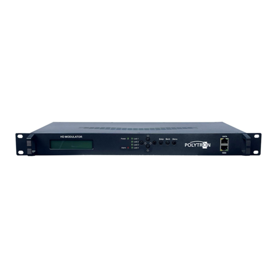
3. Funktions- und Bedienelemente Frontansicht 1 Anzeige Betriebsspannung 2 Anzeige Lock 1, Lock 2 SDI-Status, Lock 3 ASI-Status, Lock 4 nicht belegt 3 Bedientasten manuelle Programmierung Taste nach oben im Menü Taste nach unten im Menü Taste nach links im Menü Taste nach rechts im Menü... -
Page 7: Blockschaltbild / Block Diagram
4. Blockschaltbild MPEG-2 / ASI 1/2 OUT SDI 1 MPEG-4 HD TS-Auswahl Encoding SPTS1/SPTS2/ MPTS1-4 IP OUT MPEG-2 / SDI 2 MPEG-4 HD Encoding DVB-T Modulator RF OUT ASI IN... -
Page 8: Grundeinstellungen Im Werkszustand / Default Settings At Factory Reset
Signal des Modulators 1 (MPTS 1) zur Verfügung gestellt. Der Auslieferzustand kann jederzeit durch „Factory set“ hergestellt werden. Alle Transportstrominformationen werden neutral vorgegeben und können den Erfordernissen des Kabelnetzbetreibers angepasst werden. Die Grundeinstellungen der Geräte sind nachfolgend dargestellt: HDS 2 T/IP Netzwerk* IP Adresse 192.168.001.225 Subnetzmaske 255.255.255.000... -
Page 9: Manuelle Programmierung Am Gerät / Manual Programming On The Device
7. Manuelle Programmierung am Gerät 7.1 LCD Anzeige nach dem Einschalten Start up Please wait … (Konfiguration wird geladen und aktualisiert) Encoder Modulator IP-Adresse des Gerätes 192.168.1.225 7.2 Übersicht Hauptmenü Das Hauptmenü erscheint nach 2-maligen Betätigen der Taste „Menu“. Mit den Pfeiltasten erfolgt die Steuerung durch das Menü. Mit „Enter“... -
Page 10: Übersicht Untermenüs / Overview Sub Menus
7.3 Übersicht Untermenüs Input Settings Main menu Input Settings „Enter“ „Enter“ Input Settings 1. SDI HD Anzeige Eingangsstatus und - 1. SDI HD Status informationen SDI 1 1. SDI HD Konfiguration Video SDI 1 Video 1. SDI HD Konfiguration Audio SDI 1 Audio Input Settings „Enter“... - Page 11 Audio Audio Format MPEG2, MPEG2 AAC, MPEG4 AAC, AC3 Standard: MPEG2 -31 dB…-1 dB (nur änderbar im Format “AC3”) Dialog Normal Standard: -31 Audio Bitrate 64, 96, 128, 192, 256, 320 kbps Standard: 192 kbps Audio Gain 100…400 % Standard: 100 % Audio Group Group 1, Group 2, Group 3, Group 4 Standard: Group 1...
- Page 12 „Enter“ Modulator Einstellschritte gemäß „Channel 1“ Channel 3 „Enter“ Modulator Einstellschritte gemäß „Channel 1“ Channel 4 Channel 1 / Channel 2 / Channel 3 / Channel 4 Level (CH Carriers) -20 dBm…-3 dBm Standard: -3 dBm (106 dBµV) Channel Enable On, Off Standard: On 50 MHz…960 MHz...
- Page 13 Das Signal des ASI-Ausganges ASI OUT 1 liegt gespiegelt auch am ASI-Ausgang ASI OUT 2 an. Als ASI-Signal kön- nen die Transportströme MPTS 1, MPTS 2, MPTS 3, MPTS 4, SPTS 1 oder SPTS 2 ausgewählt werden. MPTS 1 / MPTS 2 / MPTS 3 / MPTS 4 Data enable On, Off Standard: MPTS 1: On, MPTS 2: Off,...
- Page 14 Einstellung der Daten für den Streaming-Port „Enter“ Data Network Konfiguration IP-Adresse Datenport Data Standard: 192.168.2.137 Konfiguration Subnetzmaske Data Datenport Subnet mask Standard: 255.255.255.0 Data Konfiguration Gateway des Gerätes Standard: 192.168.2.0 Gateway Data Anzeige MAC-Adresse (wird vom Hersteller zugewiesen) MAC address System Main menu System...
-
Page 15: Programmierung Über Das Ethernet-Interface (Nms) / Programming Via The Ethernet Interface (Nms)
Status Main menu Status „Enter“ „Enter“ Status Anzeige der Alarmmeldungen Alarm Status „Enter“ Anzeige der Betriebszeit Uptime 8. Programmierung über Webbrowser (NMS) Sollen Änderungen an der Grundkonfiguration via Ethernet-Interface vorgenommen werden, so ist die jeweilige HTML- Bedienoberfläche über einen angeschlossenen Computer aufzurufen. Als Bedienprogramm wird ein Internetbrowser benötigt. -
Page 16: Statusanzeige (Welcome) / Status Indication (Welcome)
HINWEIS Sind Passwort oder Username nicht (oder nicht mehr) bekannt, kann über den Menüpunkt „System Factory set“ ein Rücksetzen in den Auslieferzustand erfolgen. Das Gerät erhält dadurch wieder die oben beschriebenen Zugangsdaten und Grundeinstellungen. Bereits individualisierte Grundeinstellungen, außer den Ethernet-Zugangsdaten, gehen verlo- ren. - Page 17 Aspect Ratio Festlegung, wie das Signal für den MPEG-Header interpretiert werden soll. Auto, 4:3, 16:9 Standard: Auto Video Cache Aktivierung des Videobuffer On, Off Standard: On Video Bitrate (Mbps) Bandbreite für Video des jeweiligen Encoders. 1 Mbps…19,5 Mbps Standard: 14 Mbps H.264 Profile Festlegung des Profils entsprechend der spezifischen Anwendung.
-
Page 18: Menü „Modulator" Dvb-T / Menu "Modulator" Dvb-T
Bitrate Festlegung der Audio-Datenrate des jeweiligen Encoders. 64, 96, 128, 192, 256, 320 kbps Standard: 192 kbps Audio Delay Verzögerung des Ausgangssignals Standard: 0 ms -1000 ms…1000 ms 3. Status In diesem Bereich werden die Statusinformationen über das Eingangssignal (Eingangs-Erkennung, -Bitrate) sowie dem Encoder-Chipset angezeigt. - Page 19 Start Frequency / Frequency Festlegung der Start-Frequenz/Frequenz zur Vergabe der Ausgangsfrequenzen. 30…960 MHz Standard: 650,00 / 658,00 / 666,00 / 674,00 MHz BandWidth Festlegung der Kanal-Bandbreite zur automatischen Vergabe der Ausgangskanäle. 6 MHz, 7 MHz, 8 MHz Standard: 8 MHz Code Rate Konfiguration der Code-Rate der Ausgangssignale.
-
Page 20: Menü „Ts Config" / Menu "Ts Config
8.5 Menü „TS Config“ In diesem Menü erfolgt die Konfiguration der Ausgangstransportströme. Nach einem Klick auf „Output TS x” wird die Auswahlliste der TS-Ausgangskanäle 1-4 angezeigt. Durch Klicken auf den gewünschten TS-Ausgangskanal wird dieser ausgewählt. Der Button „Stream Select” dient der Zuordnung der Streams zum ausgewählten Ausgangstransportstrom. Zur Akti- vierung bitte den Button betätigen, danach öffnet sich das folgende Menüfenster. -
Page 21: Menü „Output Settings" / Menu "Output Settings
Der Button „General” dient der Anpassung der Transportstromdaten (Stream, NIT). Zur Aktivierung bitte den Button betätigen, danach öffnet sich das folgende Menüfenster und es können alle notwendigen Einstellungen vorgenommen werden. Die Einstellungen beziehen sich immer auf den ausgewählten Transportstrom (im Beispiel „Output TS 1). Die Übernahme der Einstellungen erfolgt durch Betätigen des Buttons „Apply“. -
Page 22: Menüpunkt „System" / Menu Item "System
Im Bereich „ASI Settings“ erfolgt die Zuordnung eines IP-Stream-Transportstromes zu den beiden ASI-Ausgängen. Die Übernahme der Einstellungen erfolgt durch Betätigen des Buttons „Apply“. 9. Menüpunkt „System“ Im Menüpunkt „System“ erfolgen die allgemeinen Einstellungen, das Update der gerätespezifischen Parameter sowie bietet dieser Menüpunkt die Möglichkeit der Speicherung von Daten. 9.1 Menü... -
Page 23: Menü „Configuration" / Menu "Configuration
9.3 Menü „Configuration“ Im Menü „Configuration“ stehen 5 Auswahlfelder, „Save“, „Restore“, „Factory Set“, „Backup“ und „Load“ zur Verfü- gung. Funktion auswählen „Save“ Durch Betätigen des Buttons „Save“ werden alle Einstellungen im Gerät dauerhaft gespeichert. Wurde der Button „Save“ nicht betätigt, gehen alle Einstellungen bei einem Reboot bzw. beim HINWEIS Ausschalten des Gerätes verloren! „Restore“... -
Page 24: Menü „Date/Time" / Menu "Date/Time
9.5 Menü „Date / Time“ Das Menü „Date / Time“ ermöglicht die Auswahl einer länderspezifischen Zeitzone sowie die Verbindung zu einem NTP-Server. Im Falle eines NTP-Servers muss die URL des Servers angegeben werden. Dafür müssen die "IP- Einstellungen" korrekt sein und es muss sichergestellt werden, dass das Gerät auf den NTP-Server zugreifen kann, um die korrekte Uhrzeit zu erhalten. - Page 25 Save the operating instructions for later use. All operating instructions can be found on our website at: https://polytron.de/index.php/en/services/operating-manuals Approved use Use the device only at the permissible operating locations, under the permissible environmental conditions and for the purpose described in the operating instructions.
- Page 26 In compliance with the following requirements: WEEE Directive (2012/19/EU) WEEE-Reg.-Nr. DE 51035844 Italy Direttiva RAEE (2012/19/UE) Raccolta carta Raccolta plastica Guarantee conditions § The general terms and conditions of Polytron-Vertrieb GmbH apply. The general terms and conditions can be found on our website at: https://polytron.de/index.php/en/company/general-terms-and-conditions...
- Page 27 2. General function description The HDS 2 T/IP is an MPEG encoder with integrated DVB modulator. Up to 2 SDI signals can be encoded and up to 4 program bouquets can be provided in DVB-T which contain of the SDI and the ASI IN signals. The integrated modula- tor generates DVB compliant signals that contain all the necessary program and service tables (PAT, PMT and SDT).
- Page 28 3. Function and control elements Front view 1 Power indicator 2 Lock 1, Lock 2 SDI status, Lock 3 ASI status, Lock 4 not used 3 Buttons for manually programing Button up in the menu Button down in the menu Button left in the menu Button...
- Page 29 4. Block diagram MPEG-2 / ASI 1/2 OUT SDI 1 MPEG-4 HD TS selection Encoding SPTS1/SPTS2/ MPTS1-4 IP OUT MPEG-2 / SDI 2 MPEG-4 HD Encoding DVB-T Modulator RF OUT ASI IN...
- Page 30 The delivery status can be reset at any time by "Factory set". All transport stream information is given neutral and can be adapted to the requirements of the cable network operator. The basic settings of the devices are shown below: HDS 2 T/IP Network* IP address 192.168.001.225...
- Page 31 7. Manual programing on the device 7.1 LCD Display after switching on Start up Please wait … (Configuration is loaded and updated) Encoder Modulator IP address of the device 192.168.1.225 7.2 Overview Main menu The main menu appears after pressing the "Menu" button twice. Use the arrow keys to control the menu.
- Page 32 7.3 Overview Submenus Input Settings Main menu Input Settings „Enter“ „Enter“ Input Settings 1. SDI HD Display input status and information 1. SDI HD Status for SDI 1 1. SDI HD Configuration video settings SDI 1 Video 1. SDI HD Configuration audio settings SDI 1 Audio Input Settings...
- Page 33 Audio Audio Format MPEG2, MPEG2 AAC, MPEG4 AAC, AC3 Standard: MPEG2 -31 dB…-1 dB (only changeable in format “AC3”) Dialog Normal Standard: -31 Audio bitrate 64, 96, 128, 192, 256, 320 kbps Standard: 192 kbps 100…400 % Audio Gain Standard: 100 % Audio Group Group 1, Group 2, Group 3, Group 4 Standard: Group 1...
- Page 34 „Enter“ Modulator Setting steps according to „Channel 1“ Channel 3 „Enter“ Modulator Setting steps according to „Channel 1“ Channel 4 Channel 1 / Channel 2 / Channel 3 / Channel 4 Level (CH Carriers) -20 dBm…-3 dBm Standard: -3 dBm (106 dBµV) Channel Enable On, Off Standard: On...
- Page 35 The signal of the ASI output ASI OUT 1 is also mirrored at the ASI output ASI OUT 2. The transport streams MPTS 1, MPTS 2, MPTS 3, MPTS 4, SPTS 1 or SPTS 2 can be selected as the ASI output signal. MPTS 1 / MPTS 2 / MPTS 3 / MPTS 4 Data enable On, Off...
- Page 36 Setting the data for streaming port Configuration of IP address of the „Enter“ Data Network data port Data Standard: 192.168.2.137 Configuration of subnet mask of the Data data port Subnet mask Standard: 255.255.255.0 Data Configuration of gateway of the device Standard: 192.168.2.0 Gateway Data...
- Page 37 Status Main menu Status „Enter“ „Enter“ Status Display the alarm messages Alarm Status „Enter“ Display the running time Uptime 8. Programming via the Ethernet interface (NMS) If changes to the basic configuration are made via the Ethernet interface, the respective HTML user interface must be accessed via a connected computer.
- Page 38 NOTE If the password or user name is not (or no longer) known, a reset to the factory setting can be carried out via the menu item "System Factory set“. The device receives the access data and basic settings described above. Even individu- alized basic settings, except the Ethernet access data, are lost.
- Page 39 Video Cache Activation of the video buffer On, Off Standard: On Video Bitrate (Mbps) Bandwidth for video of the respective encoder 1 Mbps …19.5 Mbps Standard: 14 Mbps H.264 Profile Definition of the profile according to the specific application Automatic, Baseline Profile, Main Profile, High Profile Standard: Main Profile Out Resolution If the "Auto Config"...
- Page 40 Audio Delay Delay of the output signal Standard: 0 ms -1000 ms…1000 ms 3. Status The status information about the input signal (input detection, bit rate) and the encoder chipset is displayed in this area. With the "Apply" button the values selected in the menu are set. NOTE The combination of selected video format, video bitrate, low delay mode and resolution of the signal source has an influence on the delay of the input signal!
- Page 41 Code Rate Configuration of the code rate of the output signals. 1/2, 2/3, 3/4, 5/6, 7/8 Standard: 7/8 Constellation Configuration of the constellation of the output signals. QPSK, 16 QAM, 64 QAM Standard: 64 QAM FFT Mode Setting of the FFT mode of the output signals. 2K, 4K, 8K Standard: 2K Guard Interval...
- Page 42 The "Input and output range" is set using the control panels in the "Setting range". CA filter function activate/deactivate (Avoid interference from the encryption function) PID remapping activate/deactivate Refresh of program information at input Refresh of program information at output After selection of an input program click on this button to add the respective program to the output TS Remove selected programs from the output TS Selection of all input programs...
- Page 43 8.6 Menu “Output Settings“ The parameters for the IP output transport streams can be configured in this menu. Click here to set the output parameters for all IP channels. Click here to set the output parameters for individual IP channels. The parameters for all IP output channels are set The parameters for each IP output channel are set in this menu.
- Page 44 Menu item “System“ In the menu item “System“ the network parameters will be set. Also it is possible to update the device specific pa- rameters and save or load the device data. 9.1 Menu “Network“ In the “Network“ menu, the Ethernet interface for the management NMS) of the device via the web browser will be configured.
- Page 45 9.3 Menu “Configuration“ In the menu “Configuration“ 5 selection buttons are provided, “Save“, “Restore“, “Factory Set“, “Backup“ and “Load“. Select function “Save“ By pressing the “Save“ button, all settings in the device are stored permanently. NOTE If the button "Save" has not been pressed, all settings will be lost during a reboot or when the device is switched off! “Restore“...
- Page 46 9.5 Menu “Date / Time“ In the menu “Date / Time“, the selection of the country specific time zone and the connection to a NTP server can be done. In the case of a NTP server, the URL of the server must be specified. For this, the "IP settings" must be correct and the device must be able to access the server to get the correct time.
-
Page 47: 10. Technische Daten / Technical Data
10. Technische Daten / Technical data Typ / Type HDS 2 T/IP Artikel-Nr. / Article no. 5741698 Encoder Video Videoformat / Video Format MPEG2, MPEG4 AVC/H.264 Eingang / Input 2x SDI Auflösung / Resolution 1920*1080_60p, 1920*1080_50p, (-for MPEG4 AVC/H.264 only) - Page 48 Technische Hotline Technical hotline + 49 (0) 70 81 / 1702 - 0 Telefax + 49 (0) 70 81 / 1702 - 50 Internet http://www.polytron.de eMail info@polytron.de Technische Änderungen vorbehalten Subject to change without prior notice Copyright © Polytron-Vertrieb GmbH...
Need help?
Do you have a question about the HDS 2 T/IP and is the answer not in the manual?
Questions and answers