Table of Contents
Advertisement
Quick Links
M/B For Socket 370 Pentium
Trademark:
* Pentium is registered trademark and MMX is a trademark of Intel Corporation,
the other names and brands are the property of their respective owners
* Specifications and Information contained in this documentation are furnished for information use only, and are
subject to change at any time without notice, and should not be construed as a commitment by manufacturer.
630CF/630CN
USER'S MANUAL
NO. G03-630CFR3A
Release date: JAN 2001
** Year 2001 compliant **
III
Processor
Advertisement
Table of Contents

Related Manuals for JETWAY For Socket 370


Summary of Contents for JETWAY For Socket 370
- Page 1 630CF/630CN USER'S MANUAL M/B For Socket 370 Pentium Processor NO. G03-630CFR3A Release date: JAN 2001 ** Year 2001 compliant ** Trademark: * Pentium is registered trademark and MMX is a trademark of Intel Corporation, the other names and brands are the property of their respective owners * Specifications and Information contained in this documentation are furnished for information use only, and are subject to change at any time without notice, and should not be construed as a commitment by manufacturer.
-
Page 2: Table Of Contents
TABLE OF CONTENT USER’S NOTICE................1 MANUAL REVISION INFORMATION..........2 THERMAL SOLUTIONS ..................2 CHAPTER 1 INTRODUCTION OF 630CF/630CN MOTHERBOARD 1-1 FEATURE OF MOTHERBOARD...............3 1-2 SPECIFICATION...................4 1-3 PERFORMANCE LIST.................5 1-4 LAYOUT DIAGRAM & JUMPER SETTING..........6 CHAPTER 2 HARDWARE INSTALLATION 2-1 HARDWARE INSTALLATION STEPS............8 2-2 CHECKING MOTHERBOARD'S JUMPER SETTING......8 2-3 INSTALL CPU....................9 ... - Page 3 3-8 POWER MANAGEMENT SETUP..............36 3-8-1 PM WAKE UP EVENTS................37 3-9 PNP/PCI CONFIGURATION SETUP............38 3-9-1 IRQ RESOURCES..................39 3-10 PC HEALTH STATUS.................40 3-11 FREQUENCY/VOLTAGE CONTROL .............40 3-12 LOAD STANDARD/OPTIMIZED DEFAULTS........41 3-13 SET SUPERVISOR/USER PASSWORD............42 CHAPTER 4 DRIVER & FREE PROGRAM INSTALLATION MAGIC INSTALL SUPPORTS WINDOWS 95/98/98SE/NT4.0/2000....43 4-1 VGA ..........44 INSTALL SIS 630 VGA DRIVER...
-
Page 4: User's Notice
USER’S NOTICE COPYRIGHT OF THIS MANUAL BELONGS TO MANUFACTURER. NO PART OF THIS MANUAL, INCLUDING THE PRODUCTS AND SOFTWARE DESCRIBED IN IT MAY BE REPRODUCED, TRANSMITTED OR TRANSLATED INTO ANY LANGUAGE IN ANY FORM OR BY ANY MEANS WITHOUT WRITTEN PERMISSION OF MANUFACTURER. -
Page 5: Manual Revision Information
Reversion Revision History Date Third Edition Jan 2001 Item Checklist 630CF/630CN Cable for IDE/Floppy CD for motherboard utilities □ Cable for USB Port 3/4 (Option) Cable for COM2 630CF/630CN User’s Manual Intel Processor Family Thermal Solutions As processor technology pushes to faster speeds and higher performance, thermal management becomes increasingly crucial when building computer systems. -
Page 6: Chapter 1 Introduction Of 630Cf/630Cn Motherboard
PGA/PPGA processors, and the memory size expandable to 1GB. This motherboard use the newest SiS 630 chipset provides a high performance/low cost solution for socket 370 series CPUs based system, by integrating a high performance North Bridge, advanced hardware 2D/3D GUI engine and Super-South Bridge. -
Page 7: Performance List
Design Micro ATX form factor 4 layers PCB size: 24.5x19.0cm SiS 630 Chipset Chipset Clock Generator Support 66/100/133MHz system Bus Clock (CPU Bus Clock) Support 100/133 MHz system memory clock Support 33MHz PCI Bus clock CPU Socket ... - Page 8 for different testing data values gotten by users (the different Hardware & Software configuration will result in different benchmark testing results.) CPU: Intel PIII 866MHz FC-PGA package DRAM: 128M SDRAM x2 (Hyundai GM 72V66841ET75) VGA Expansion Card: On Board VGA (Driver V1.05) Hard Disk Driver: Quantum Fireball KX20A11 BIOS:...
-
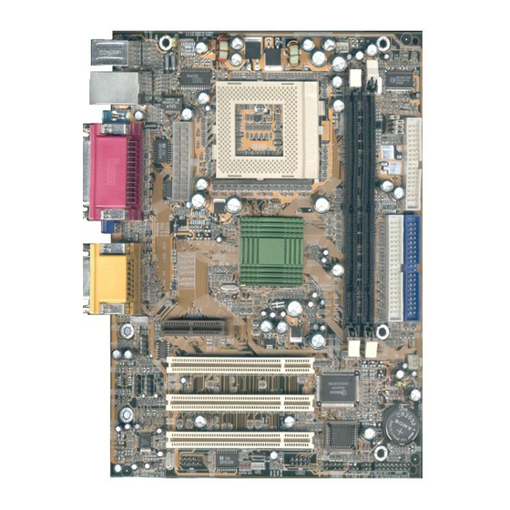
Page 9: Layout Diagram & Jumper Setting
Jumpers Jumper Name Description Page CPU & SDRAM Frequency Setting 2x4-pin Block JP10, JP11 2x2-pin Block Keyboard Power ON Function Setting 3-pin Block CMOS RAM Clear 3-pin Block Connectors Connector Name Description Page ATX Power Connector 20-pin Block p.16 KB/MOUSE PS/2 Mouse &... -
Page 10: Chapter 2 Hardware Installation
Connector USB Port Connector 2x4-pin Connector p.17 LAN Port Connector RJ45 Connector p.17 (Only for 630CF) PRINT Parallel Port Connector 25-pin Female p.17 VGA Port Connector 15-pin Female p.18 GAME Audio/Game Connector 3 phone jack + 15-pin Connector p.18 COM1 Serial Port COM1 Connector 9-pin Connector p.18... -
Page 11: Checking Motherboard's Jumper Setting
Before using your computer, you had better complete the following steps: 1. Check motherboard setting 2. Install CPU 3. Install Memory 4. Install Expansion cards 5. Connect Ribbon cables, Panel wires, and power supply 6. Setup BIOS 7. Install software driver & utility 2-2 Checking Motherboard’s Jumper Setting CPU &... -
Page 12: Install Cpu
CMOS RAM Clear (3-pin): JP6 A battery must be used to retain the motherboard configuration in CMOS RAM short 2-3 pins of JP6 to store the CMOS data. Note: You can clear CMOS by shorting 1-2 pin, while the system is off. Then return to 2-3 pin position. - Page 13 Serial Port - a low speed interface typically used for mouse and external modems. Parallel Port - a low speed interface typically used for printers. PS/2 - a low speed interface used for mouse and keyboards. USB - Universal Serial Bus - a medium speed interface typically used for mouse, keyboards, scanners, scanners, and some digital cameras.
-
Page 14: Setting Cpu Bus Clock & Memory Clock Jumper
Celeron FC–PGA On the surface of the CPU as shown on the right picture, under the word of “Celeron” the code is: 566/128/66/1.5V 566 : CPU internal frequency, where here is 566MHz 128 : the size of L2 cache, where here is 128K front side bus frequency, where here is 66MHz 1.5V : the voltage for the CPU... -
Page 15: Overclock Running
may cause the processor and motherboard overheat and damage, you may install an auxiliary cooling FAN, if necessary. To install a CPU, first turn off your system and remove its cover. Locate the ZIF socket and open it by first pulling the level sideways away from the socket then upward to a 90-degree angle. -
Page 16: Install Memory
133/133 CMOS Setup Utility - Copyright (C) 1984-2000 Award Software Frequency/Voltage Control Item Help Cyrix III Clock Ratio Default Auto Detect DIMM/PCI Clk Enabled Spread Spectrum Disabled CPU Host/DRAM Clock Menu Level > CPU Host/DRAM Clock Default Default CPU Clock Ratio Jumpless x 3.0 66/66MHz .. - Page 17 Generally, installing SDRAM modules to your motherboard is very easy, you can refer to figure 2-4 to see what a 168-Pin PC100 & PC133 SDRAM module looks like. Figure 2-4 NOTE! When you install DIMM module fully into the DIMM socket the eject tab should be locked into the DIMM module very fimly and fit into its indention on both sides.
-
Page 18: Expansion Card
Align the card’s connectors and press firmly. Secure the card on the slot with the screen you remove above. Replace the computer system’s cover. Set up the BIOS if necessary. Install the necessary software driver for your expansion card. 2-5-2 Assigning IRQs For Expansion Card Some expansion cards need an IRQ to operate. -
Page 19: Interrupt Request Table For This Motherboard
IMPORTANT! If using PCI cards on shared slots, make sure that the drivers support “Shared IRQ” or that the cards don’t need IRQ assignments. Conflicts will arise between the two PCI groups that will make the system unstable or cards inoperable. 2-6 Connectors, Headers 2-6-1 Connectors Power Connector: ATX (20-pin block) - Page 20 LAN Port connector: LAN (Only for 630CF) This connector is standard RJ45 connector for Network connector. Parallel Port Connector (25-pin female): PRINT Parallel Port connector is a 25-pin D-Subminiature Receptacle connector. The On-board Parallel Port can be disabled through the BIOS SETUP. Please refer to Chapter 3 “INTEGRATED PERIPHERALS SETUP”...
- Page 21 Audio and Game Connector : GAME This Connector are 3 phone Jack for LINE-OUT, LINE-IN, MIC and a 15-pin D-Subminiature Receptacle Connector for joystick/MIDI Device. Line-out : Audio output to speaker Line-in : Audio input to sound chip MIC : Microphone Connector Game/MIDI : For joystick or MIDI Device Serial Port COM1: COM1...
- Page 22 Floppy drive Connector (34-pin block): FDD This connector supports the provided floppy drive ribbon cable. After connecting the single plug end to motherboard, connect the two plugs at other end to the floppy drives. (10) Primary IDE Connector (40-pin block): IDE1 This connector supports the provided IDE hard disk ribbon cable.
-
Page 23: Headers
Two hard disks can be connected to each connector. The first HDD is referred to as the “Master” and the second HDD is referred to as the “Slave”. For performance issues, we strongly suggest you don’t install a CD-ROM or DVD-ROM drive on the same IDE channel as a hard disk. - Page 24 method of rebooting in order to prolong the lift of the system’s power supply. See the figure below. Keyboard lock switch: KEYLOCK This 2-pin connector connects to the case-mounted key switch for locking the keyboard for security purposes. Speaker connector: SPKR This 4-pin connector connects to the case-mounted speaker.
- Page 25 (11) FAN Speed Headers (3-pin): CPUFAN, SYSFAN These connectors support cooling fans of 350mA (4.2 Watts) or less, depending on the fan manufacturer, the wire and plug may be different. The red wire should be positive, while the black should be ground. Connect the fan’s plug to the board taking into consideration the polarity of connector.
-
Page 26: Starting Up Your Computer
2-7 Starting Up Your Computer 1. After all connection are made, close your computer case cover. 2. Be sure all the switch are off, and check that the power supply input voltage is set to proper position, usually in-put voltage is 220V240V or 110V120V depending on your country’s voltage used. -
Page 27: Chapter 3 Introducing Bios
6. During power-on, press <Delete> key to enter BIOS setup. Follow the instructions in BIOS SETUP. 7. Power off your computer: You must first exit or shut down your operating system before switch off the power switch. For ATX power supply, you can press ATX power switching after exiting or shutting down your operating system. -
Page 28: Getting Help
the system case. You may also restart by simultaneously pressing <Ctrl>, <Alt> and <Delete> keys. If you do not press the keys at the correct time and the system does not boot, an error message will be displayed and you will again be asked to Press <F1>... -
Page 29: Standard Cmos Features
Advanced BIOS Features Use this menu to set the Advanced Features available on your system. Advanced Chipset Features Use this menu to change the values in the chipset registers and optimize your system’s performance. Integrated Peripherals Use this menu to specify your settings for integrated peripherals. Power Management Setup Use this menu to specify your settings for power management. - Page 30 The items in Standard CMOS Setup Menu are divided into several categories. Each category includes no, one or more than one setup items. Use the arrow keys to highlight the item and then use the <PgUp> or <PgDn> keys to select the value you want in each item.
-
Page 31: Advanced Bios Features
Head number of heads Precomp write precomp Landing Zone landing zone Sector number of sectors 3-5 Advanced BIOS Features CMOS Setup Utility – Copyright(C) 1984-2000 Award Software Advanced BIOS Features Virus Warning Disabled Item Help CPU Internal Cache Enabled External Cache Enabled CPU L2 Cache ECC Checking Disabled... - Page 32 External Cache Choose Enabled or Disabled. This option enables the Level 2 cache memory. CPU L2 Cache ECC Checking Choose Enabled or Disabled. This option enables the Level 2 cache memory ECC (error check correction). Processor Number Feature This option is for Pentium III processor.
-
Page 33: Advanced Chipset Features
Sets the number of times a second to repeat a keystroke when you hold the key down. The settings are: 6, 8, 10, 12, 15, 20, 24, and 30. Typematic Delay (Msec) Sets the delay time after the key is held down before is begins to repeat the keystroke. The settings are 250, 500, 750, and 1000. -
Page 34: Advanced Dram Control
Advanced DRAM Control 1 Please refer to section 3-6-1 System BIOS Cacheable Selecting Enabled allows caching of the system BIOS ROM at F0000h-FFFFFh, resulting in better system performance. However, if any program writes to this memory area, a system error may result. The settings are: Enabled and Disabled. Video RAM Cacheable Select Enabled allows caching of the video BIOS, resulting in better system performance. -
Page 35: Integrated Peripherals
↑↓→← Move Enter:Select Item +/-/PU/PD:Value F10:Save ESC:Exit F1:General Help F5:Previous Values F6:Optimized Defaults F7:Standard Defaults 3-7 Integrated Peripherals CMOS Setup Utility – Copyright(C) 1984-2000 Award Software Integrated Peripherals > OnChip IDE Function Press Enter Item Help > OnChip Device Function Press Enter >... -
Page 36: Onchip Ide Function
3-7-1 OnChip IDE Function CMOS Setup Utility – Copyright(C) 1984-2000 Award Software OnChip IDE Function Internal PCI/IDE Both Item Help Primary Master Auto Primary Slave Auto Secondary Master PIO Auto Menu Level >> Secondary Slave Auto Primary Master UDMA Auto Primary Slave UDMA Auto... -
Page 37: Onchip Device Function
detection of the optimal number of block read/writes per sector the drive can support. The settings are: Enabled, Disabled. 3-7-2 OnChip Device Function CMOS Setup Utility – Copyright(C) 1984-2000 Award Software OnChip Device Function AC97 Sound Device Enabled Item Help Game Port Address Midi Port Address Midi Port IRQ... -
Page 38: Winbond Superio Device
3-7-3 Winbond SuperIO Device CMOS Setup Utility – Copyright(C) 1984-2000 Award Software Winbond SuperIO Device Onboard FDD Controller Enabled Item Help Onboard Serial Port 1 3F8/IRQ4 Onboard Serial Port 2 2F8/IRQ3 UART 2 Mode Normal Menu Level >> RxD,TxD Active Hi,Hi IR Transmission Delay Enabled... -
Page 39: Power Management Setup
Parallel Port Mode : Standard Parallel Port : Enhanced Parallel Port : Extended Capability Port SPP/EPP/ECP/ECP+EPP To operate the onboard parallel port as Standard Parallel Port only, choose “SPP.” To operate the onboard parallel port in the EPP modes simultaneously, choose “EPP.” By choosing “ECP”, the onboard parallel port will operate in ECP mode only. -
Page 40: Pm Wake Up Events
This determines the manner in which the monitor is blanked. The choice are Suspend off, All Modes Off, and Always On. Video Off Method This determines the manner in which the monitor is blanked. DPMS (default) Initial display power management signaling. Blank Screen This option only writes blanks to the video buffer. -
Page 41: Pnp/Pci Configuration Setup
During Enabled, the system will boot up if there’s an incoming call from the EtherNet controller. PCIPME Power Up Control This will enable the system to wake up by PCI device Power Management function. The settings are: Enabled and Disabled. KB Power ON Password This item can setting Power On Password, if you Enabled keyboard Power On function then you can Power On system by key-in the password which you setting. -
Page 42: Irq Resources
↑↓→← Move Enter:Select Item +/-/PU/PD:Value F10:Save ESC:Exit F1:General Help F5:Previous Values F6:Optimized Defaults F7:Standard Defaults Reset Configuration Data Normally, you leave this field Disabled. Select Enabled to reset Extended System Configuration Data (ESCD) when you exit Setup if you have installed a new add-on and the system reconfiguration has caused such a serious conflict that the operating system can not boot. -
Page 43: Pc Health Status
F5:Previous Values F6:Optimized Defaults F7:Standard Defaults 3-10 PC Health Status This section shows the Status of you CPU, Fan, Warning for overall system status. This is only available if there is Hardware Monitor onboard. CMOS Setup Utility – Copyright(C) 1984-2000 Award Software PC Health Status CPU Warning Temperature Disabled... -
Page 44: Load Standard/Optimized Defaults
↑↓→← Move Enter:Select Item +/-/PU/PD:Value F10:Save ESC:Exit F1:General Help F5:Previous Values F6:Optimized Defaults F7:Standard Defaults Cyrix III Clock Ratio This item allows you to set Cyrix III Clock Ratio. The settings are Default, X3.5, X3, X4, X4.5, X5, X5.5, X6. Auto Detect DIMM/PCI Clk This item allows you to enable/disable auto detect DIMM/PCI Clock. -
Page 45: Set Supervisor/User Password
3-13 Set Supervisor/User Password You can set either supervisor or user password, or both of them. The differences are: Supervisor password: Can enter and change the options of the setup menus. User password: Can only enter but do not have the right to change the options of the setup menus. -
Page 46: Chapter 4 Driver & Free Program Installation
Chapter 4 DRIVER & FREE PROGRAM INSTALLATION Check your package and there is A MAGIC INSTALL CD included. This CD consists of all DRIVERS you need and some free application programs and utility programs. In addition, this CD also include an auto detect software which can tell you which hardware is installed, and which DRIVERS needed so that your system can function properly. -
Page 47: Vga
From MAGIC INSTALL MENU you may make 8 selections: 1. VGA Install SiS 630 On-chip VGA driver 2. PC-HEALTH Install Winbond Hardware Doctor Monitoring Software 3. LAN Install PCI Fast Ethernet driver 4. SOUND Install On-chip AC’97 Audio driver 5. PC-CILLIN Install PC-CILLIN98 Anti-virus program 6. - Page 48 Multimedia Package support three types System will add program icons to the of Setup: Typical, Compact, Custom Program Folder listed. Click Next to continue, and after “Start Copying Files” Please choice Typical and Click Next to window appears click Next continue step System starting install VGA driver Install Microsoft Direct X...
-
Page 49: Pc-Health Winbond Hardware Doctor Monitoring Software
4-2 PC-HEALTH Winbond Hardware Doctor Monitoring Software The path of the file is X:\SIS630\HEALTH-W\SETUP.EXE (Only support WINDOWS 95/98/98SE/98ME) In Windows 95/98 Winbond Hardware Doctor Monitoring Software needs some system files to copy in Utility that’s why it needs install PC-HEALTH twice to complete setup. -
Page 50: Lan (Only For 630Cf) Install Sis 900 Pci Fast Ethernet Driver
2. After excuting Winbond Hardware Doctor 1. Click Program Winbond Hardware it supports system voltage, Fan speed and Doctor Hardware Doctor the Winbond CPU/SYSTEM Temperature. Because this Hardware Doctor will appears is a On-time Monitoring program therefore You can remove the Utility in Control the value will change after it detected, if Panel ... -
Page 51: Sound Install Sis 7018 Ac'97 Audio Driver And Application Software
Choice restart my computer now to finish After restart computer you can check in setting up Lan Card, click Finish to complete control Panel\System Device Manager\ setup Network adapters to make sure Lan card Driver setup completely Click NEXT when SiS PCI Lan Driver Setup appears 4-4 SOUND Install SiS 7018 AC’97 Audio Driver and... - Page 52 Click Next to install the driver in Program Select restart my computer now and click Files Folder Finish to complete setup After restart computer the system will auto Click Audio Rack when Magic Install Menu detect SiS 7018 Audio Driver and install it to appears system Run Programs Audio Rack will show next...
-
Page 53: Pc-Cillin Install Pc-Cillin98 Anti-Virus Software And Application Program
4-5 PC-CILLIN Install PC-CILLIN98 Anti-virus Software and Application program Click PC-CILLIN when MAGIC INSTALL Click NEXT when PC-CILIN 98 OEM MENU Appears SETUP APPEARS. Then click YES when the announcement of copywrite appears. Software is starting to detect HD for virus Click NEXT or choose BROWSE to change Start to install the software, choose YES or the path For the file to be stored... -
Page 54: How To Disable On-Board Sound
After install PC-CILLIN98 complete we recommand select update item to download newest virus code and setting Auto refresh virus code 4-6 How To Disable On Board Sound Function Please key in “DEL” key after power on to enter BIOS SETUP screen and choose Integrate Peripherals ...
Need help?
Do you have a question about the For Socket 370 and is the answer not in the manual?
Questions and answers