Table of Contents
Advertisement
Quick Links
NMF95 Series
User's Manual
No. G03-NMF95-F
Rev: 5.0
Release date: October 1, 2019
Trademark:
* Specifications and Information contained in this documentation are furnished for information use only, and are
subject to change at any time without notice, and should not be construed as a commitment by manufacturer.
Advertisement
Table of Contents

Related Manuals for JETWAY NMF95 Series


Summary of Contents for JETWAY NMF95 Series
- Page 1 NMF95 Series User’s Manual No. G03-NMF95-F Rev: 5.0 Release date: October 1, 2019 Trademark: * Specifications and Information contained in this documentation are furnished for information use only, and are subject to change at any time without notice, and should not be construed as a commitment by manufacturer.
-
Page 2: Table Of Contents
TABLE OF CONTENT ENVIRONMENTAL SAFETY INSTRUCTION ................iii ENVIRONMENTAL PROTECTION ANNOUCEMENT .............. iii USER’S NOTICE ........................iv MANUAL REVISION INFORMATION ..................iv ITEM CHECKLIST ........................iv CHAPTER 1 INTRODUCTION OF THE MOTHERBOARD SPECIFICATION ......................1 LAYOUT DIAGRAM ....................2 CHAPTER 2 HARDWARE INSTALLATION JUMPER SETTING ..................... -
Page 3: Environmental Safety Instruction
Environmental Safety Instruction Avoid the dusty, humidity and temperature extremes. Do not place the product in any area where it may become wet. 0 to 40 centigrade is the suitable temperature. (The figure comes from the request of the main chipset) ... -
Page 4: User's Notice
USER’S NOTICE COPYRIGHT OF THIS MANUAL BELONGS TO THE MANUFACTURER. NO PART OF THIS MANUAL, INCLUDING THE PRODUCTS AND SOFTWARE DESCRIBED IN IT MAY BE REPRODUCED, TRANSMITTED OR TRANSLATED INTO ANY LANGUAGE IN ANY FORM OR BY ANY MEANS WITHOUT WRITTEN PERMISSION OF THE MANUFACTURER. -
Page 5: Specification
Chapter 1 Introduction of the Motherboard 1-1 Specification Spec Description Micro-ATX form factor; PCB size: 24.5 x24.5 cm Design ® Intel Q87/H81 Express Chipset Chipset ® ® Supports Intel Core™ i7, Core™ i5, Core™ i3 series, Pentium CPU Socket processor in LAG1150 Package (Max. -
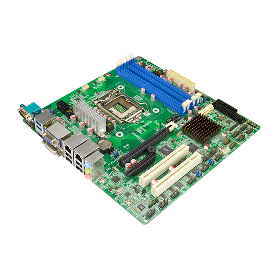
Page 6: Layout Diagram
Fan header x 3 1-2 Layout Diagram Rear IO Diagram RJ-45 LAN Ports Serial Port VGA Port USB 3.0 Ports Line-IN/ Optical SPDIF OUT Line-OUT MIC-IN HDMI Port DVI-D Port Display Port USB 2.0 Ports Motherboard Internal Diagram --For NMF95-Q87: CPUFAN Header SYS FAN1 Header Serial Port over... - Page 7 Motherboard Internal Diagram --For NMF95-H81: CPUFAN Header SYS FAN1 Header Serial Port over Display Port ATX 12V Power Connector DDRIII USB 3.0 Ports DIMM Slot x 2 over HDMI Port LGA 1150 VGA Port over CPU Socket DVI–D Port ATX Power Connector RJ-45 LAN Ports Over USB 2.0 Ports...
- Page 8 Motherboard Jumper Position JBAT CASE_OPEN Jumper Jumper Name Description COM1 Port Pin9 Function Select 4-pin Block COM2 Header Pin9 Function Select 4-pin Block COM3 Header Pin9 Function Select 4-pin Block JBAT CMOS RAM Clear Function Setting 3-pin Block Mini PCI-E/ MSATA Slot (MSATA )VCC3.3V/3.3VSB 3-pin Block Select ME_Features Setting...
- Page 9 Connectors Connector Name ATXPWR Main Power Connector ATX12V ATX 12V Power Connector COM1 Serial Port COM Connector Display Port USB1 USB 3.0 Connector X2 HDMI High-Definition Multimedia Interface Video Graphic Attach Connector DVI1 DVI-D Port Connector UL1(Top)/UL2(Top) RJ-45 LAN Connector X2 UL1(Middle &...
-
Page 10: Chapter 2 Hardware Installation
Chapter 2 Hardware Installation 2-1 Jumper Setting JP1 (4-pin): COM1 Port Pin9 Function Select JP1→COM1 Port 2 4 6 2 4 6 1 3 5 1 3 5 2-4 Closed: 3-4 Closed: 4-6 Closed: RI=RS232 RI= 5V; RI= 12V; JP5 (4-pin): COM2 Header Pin9 Function Select JP5→COM2 Header 2 4 6 2 4 6... - Page 11 JBAT (3-pin): Clear CMOS Function Settings JBAT 1-2 Closed: Normal; 2-3 Closed:Clear CMOS CMOS Clear Setting JP2 (3-pin): MSATA/ Mini PCI-E (MSATA) Slot VCC 3.3V/3.3 VSB Select JP2→MSATA VCC 1-2 Closed : MSATA/MINI PCI-E Slot VCC= 3.3V; 2-3 Closed :MSATA/MINI PCI-E Slot VCC=3.3VSB JP4 (2-pin): ME Features Setting 1-2 Open:ME Features Enabled;...
- Page 12 CASE_ OPEN (2-pin): Case Open Message Display Function Select CASE_OPEN 1-2 Open: Normal; 1-2 Closed : Case Open Display. Pin 1-2 Closed: Case open display function enabled. Use needs to enter BIOS and enable ‘Case Open Detect’ function. In this case if you case is removed, next time when you restart your computer a message will be displayed onscreen to inform you of this.
-
Page 13: Connectors And Headers
Connectors and Headers 2-2-1 Rear I/O Back Panel Connectors RJ-45 LAN Ports Serial Port VGA Port USB 3.0 Ports Line-IN/ Optical SPDIF OUT Line-OUT MIC-IN HDMI Port DVI-D Port Display Port USB 2.0 Ports (1) Serial port Connector: COM1 These two serial ports are for user to connect compatible mouse, modern or other peripherals. -
Page 14: Motherboard Internal Connectors
2-2-2 Motherboard Internal Connectors ATXPWR (24-pin block): Main Power Connector ATX Power Supply connector: This is a new defined 24-pins connector that usually comes with ATX case. The ATX Power Supply allows using soft power on momentary switch that connect from the front panel switch to 2-pins Power On jumper pole on the motherboard. - Page 15 (2) ATX12V (8-pin block): 12V Power Connector This is a new defined 8-pin connector that usually comes with ATX Power Supply that supports extra 12V voltage to maintain system power consumption. Without this connector might cause system unstable because the power supply can not provide sufficient current for system.
-
Page 16: Header Pin Definition
2-2-3 Header Pin Definition (1) FP_AUDIO (9-pin): Line-Out, MIC-In Header This header is connected to Front Panel Line-out, MIC connector with cable. FP_AUDIO Pin 1 Line-Out, M I C Header (2) CD_IN (4-pin): CD AUDIO-In Header CDIN header is for CD-Audio Input signal. Please connect it to CD-ROM CD-Audio output connector. - Page 17 (4) KBMS1 (6-pin): PS/2 Keyboard & Mouse Header Pin1 (5) GPIO_CON (10-pin): GPIO Header Pin 1 (6) CIR_CON (7-Pin): CIR Header Pin 1 CIR Header...
- Page 18 (7) TPM (19-pin): TPM Header Pin 1 (8) USB 3.0 Port Header (19-pin): USB2* Pin 1 SSRX1 SSRX1 SSRX2- SSRX2+ SSTX1- SSTX2- SSTX1+ SSTX2+ *Note: USB2 (USB 3.0 header) header is only optional for Model NMF95-Q87. (9) USB 2.0 Port Headers (9-pin): USB3/USB4* Pin 1 *Note: USB4 (USB 2.0 header) header is only optional for Model NMF95-Q87.
- Page 19 (10) JW-FP (9-pin): Front Panel Header Pin1 PWRLED+ HDDLED+ PWRLED- HDDLED- PWRBTN RSTSW (11) PWRLED (3-pin): PWR LED Header Pin 1 PWRLED+ PWRLED - PWRLED - (12) SPEAK (4-pin): Speaker Header Pin 1 SPK + SPK -...
- Page 20 (13) COM2/3/4/5/6/7/8/9/10 (9-Pin): Serial Port Header Pin6 Pin1 Pin5 (14)SM_BUS (4-pin): SM BUS Header SMBUS_DATA SMBUS_CLK Pin 1 (15)NIC_LED1/ NIC_LED2 (2-pin): LANLED Header Pin1 LED+ LED-...
- Page 21 (16) SYSFAN1/SYSFAN2/CPUFAN (4-pin): FAN Headers Pin1 CPUFAN/SYSFAN1/SYSFAN2 (17) Dual Channel Memory Installation config Slot 1 Slot 2 Slot 3 Slot 4 install install install install install install install install Notice! For dual channel installation, you need to install the same brand, speed, size and type memory module.
-
Page 22: Chapter 3 Introducing Bios
Chapter 3 Introducing BIOS Notice! The BIOS options in this manual are for reference only. Different configurations may lead to difference in BIOS screen and BIOS screens in manuals are usually the first BIOS version when the board is released and may be different from your purchased motherboard. Users are welcome to download the latest BIOS version form our official website. -
Page 23: Function Keys
Menu Bar General Help Items Current Setting Value Menu Items Function Keys BIOS Menu Screen Function Keys In the above BIOS Setup main menu of, you can see several options. We will explain these options step by step in the following pages of this chapter, but let us first see a short description of the function keys you may use here: ... -
Page 24: Menu Bars
Press F1 to pop up a small help window that describes the appropriate keys to use and the possible selections for the highlighted item. To exit the Help Window, press <Esc>. 3-5 Menu Bars There are six menu bars on top of BIOS screen: Main To change system basic configuration Advanced... -
Page 25: Advanced Menu
3-7 Advanced Menu ERP Function Use this item to set ERP function for this board. The optional settings are: [Auto]; [Disabled]. This item should be set as [Disabled] if you wish to have Active All Wakeup Function. PCI Subsystem Settings Press [Enter] to enter and make settings for the following sub-items: PCI Common Settings: PCI Latency Timer... - Page 26 Use this item to set maximum payload of PCI Express device or allow system BIOS to select the value. Maximum Read Request Use this item to set maximum read request size of PCI Express device or allow system BIOS to select the value. ...
- Page 27 This item should be set as [Disabled] for Windows XP. Execute Disable Bit The optional settings: [Disabled]; [Enabled]. Intel Virtualization Technology The optional settings: [Enabled]; [Disabled]. When set as [Enabled], a VHM can utilize the additional hardware capabilities provided by Vanderpool Technology. EIST Use this item to enable or disable Intel SpeedStep.
- Page 28 The optional settings are: [Default]; [Gen1]; [Gen2]; [Gen3]. *When set as [AHCI] or [RAID] * (optional forNMF95-Q87), user can also make further settings for each available SATA ports or MSATA port: Serial ATA Port 1/2/3/4/5/6/mSATA Port 1/ Port 2/ Port 3/ Port 4*/ Port 5*/MMPE(mSATA) The optional settings: [Disabled];...
- Page 29 Press [Enter] to view ME information and make settings for ‘Firmware Update Configuration’. Firmware Update Configuration Press [Enter] to make settings for ME FW Image RE-Flash. ME FW Image RE-Flash Use this item to enable or disable ME FW Image Re-Flash function. ...
- Page 30 Press [Enter] to go to next screen to enable or disable ‘Automatic Acoustic Management’. USB Configuration Press [Enter] to make settings for the following sub-items: Legacy USB Support The optional settings are: [Enabled]; [Disabled]; [Auto]. [Enabled]: To enable legacy USB support. [Disabled]: to keep USB devices available only for EFI specification, [Auto]: To disable legacy support if no USB devices are connected.
- Page 31 Select RS232/RS422/RS485 The optional settings are: [RS422]; [RS232]; [RS485]. Mode Speed Select The optional settings are: [RS232/RS422/RS485=250kbsp]; [RS232=1Mbsp, RS422/RS485=10Mbsp]. COM2 Port Configuration Press [Enter] to make settings for the following sub-items: Serial Port Use this item to enable or disable serial port (COM). Change Settings Use this item to select an optimal setting for super IO device.
-
Page 32: Chipset Menu
The optional settings are: [Disabled]; [70 C/158 F]; [75 C/167 F]; [80 C/176 F]; [85 C/185 SmartFan Configuration Press [Enter] to make settings for SmartFan Configuration: CPUFAN 3/4 Pin Fan Select The optional settings are: [3 pin]; [4 pin]. SYSFAN1 3/4 Pin Fan Select The optional settings are: [3 pin];... - Page 33 USB Configuration XHCI Mode Use this item to select mode of operation for XHCI controller. The optional settings are: [Smart Auto]; [Auto]; [Enabled]; [Disabled]; [Manual]. *When set as [Disabled], the following sub-items shall appear: EHCI1/EHCI2 Use this item to control the USB EHCI (USB 2.0) functions. One EHCI controller must always be enabled.
- Page 34 Press [Enter] to make further settings for Graphics Configuration. Graphics Configuration Primary IGFX Boot Display Use this item to select the video device which will be activated during POST. This has no effect if external graphics present. Secondary boot display selection will appear based on your selection.
-
Page 35: Boot Menu
PEG is not the currently active device. The optional settings are: [Disabled]; [Auto]; [ASPM L0s]; [ASPM L1]; [ASPM L0sL1]. Memory Configuration Press [Enter] to view current memory configuration and make settings for the following sub-items: Memory Frequency Limiter Use this item to set maximum memory frequency selection in Mhz. The optional settings are: [Auto];... -
Page 36: Security Menu
Launch Storage OpROM policy This option controls the execution of UEFI and Legacy Storage OpROM. The optional settings are: [Do not launch]; [UEFI only]; [Legacy only]. Launch Video OpROM policy This option controls the execution of UEFI and Legacy Video OpROM. The optional settings are: [Do not launch];... -
Page 37: Save & Exit Menu
3-11 Save & Exit Menu Save Changes and Reset This item allows user to reset the system after saving the changes. Discard Changes and Reset This item allows user to reset the system without saving any changes. Restore Defaults Use this item to restore /load default values for all the setup options. Save as User Defaults Use this item to save the changes done so far as user defaults.
Need help?
Do you have a question about the NMF95 Series and is the answer not in the manual?
Questions and answers