Table of Contents
Advertisement
Quick Links
Technical Manual
Of
Intel Bay Trail Series CPU
Based Mini-ITX M/B
NO.G03-NF9M-F
Revision: 1.0
Release date: March 12, 2014
Trademark:
* Specifications and Information contained in this documentation are furnished for information use only, and are
subject to change at any time without notice, and should not be construed as a commitment by manufacturer.
Advertisement
Table of Contents

Related Manuals for JETWAY NF9M


Summary of Contents for JETWAY NF9M
- Page 1 Technical Manual Intel Bay Trail Series CPU Based Mini-ITX M/B NO.G03-NF9M-F Revision: 1.0 Release date: March 12, 2014 Trademark: * Specifications and Information contained in this documentation are furnished for information use only, and are subject to change at any time without notice, and should not be construed as a commitment by manufacturer.
- Page 2 Environmental Protection Announcement Do not dispose this electronic device into the trash while discarding. To minimize pollution and ensure environment protection of mother earth, please recycle.
-
Page 3: Table Of Contents
TABLE OF CONTENT ENVIRONMENTAL SAFETY INSTRUCTION ................iv USER’S NOTICE ........................v MANUAL REVISION INFORMATION ..................v ITEM CHECKLIST ........................v CHAPTER 1 INTRODUCTION OF THE MOTHERBOARD FEATURE OF MOTHERBOARD ................1 SPECIFICATION ......................2 LAYOUT DIAGRAM ....................3 CHAPTER 2 HARDWARE INSTALLATION JUMPER SETTING ..................... -
Page 4: Environmental Safety Instruction
Environmental Safety Instruction Avoid the dusty, humidity and temperature extremes. Do not place the product in any area where it may become wet. 0 to 60 centigrade is the suitable temperature. (The figure comes from the request of the main chipset) ... -
Page 5: User's Notice
USER’S NOTICE COPYRIGHT OF THIS MANUAL BELONGS TO THE MANUFACTURER. NO PART OF THIS MANUAL, INCLUDING THE PRODUCTS AND SOFTWARE DESCRIBED IN IT MAY BE REPRODUCED, TRANSMITTED OR TRANSLATED INTO ANY LANGUAGE IN ANY FORM OR BY ANY MEANS WITHOUT WRITTEN PERMISSION OF THE MANUFACTURER. -
Page 6: Chapter 1 Introduction Of The Motherboard Feature Of Motherboard
Chapter 1 Introduction of the Motherboard Feature of Motherboard ® Onboard Intel Bay Trail Series Processor, with low power consumption never denies high performance Support 2 * DDRIIIL SO-DIMM 1066/1333 MHz up to 8GB Support Mini-PCIE connector ... -
Page 7: Specification
Specification Spec Description 6 layers; PCB size: 17x 17 cm Design ® NF9M-2930 Series: Intel Bay Trail-M N2930 SoC CPU Embedded CPU ® NF9M-3827 Series: Intel Bay Trail-I E3827 SoC CPU 2 * DDRIIIL SODIMM Slot for un-buffered dual channel DDRIIIL... -
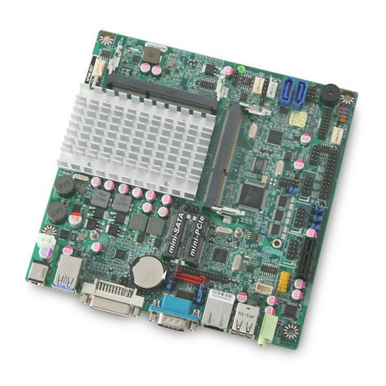
Page 8: Layout Diagram
1* SPEAK_CON header 1* Parallel port header 3* Serial port header 1* USB 2.0 header (Expansible to 2* USB 2.0 ports) 1* USB 3.0 header (Expansible to 2* USB 3.0 ports) 1* Power LED & speaker header ... - Page 9 Motherboard Internal Diagram 9V~36V Internal Power connector SYSFAN1 Header 9V ~36V DC Power-in Connector USB 3.0 Port Over USB 2.0 Port Intel CPU DDR3L SODIMM Slot (SODIMM1) Half-size Mini-PCIE Slot (MPE) DVI-I Port M-SATA Slot LAN_LED Header DDR3L SODIMM Slot (SODIMM2) COM1 Port SMBUS Header...
-
Page 10: Jumper Position
Jumper Position: JBAT ME_RTC COPEN AT-MODE SYSFAN-DET... - Page 11 Jumper Jumper Name Description JBAT CMOS RAM Clear Function Setting 2-Pin Block ME_RTC Clear ME RTC Function Setting 2-Pin Block COPEN Case Open Message Display Function 2-Pin Block AT_MODE AT Mode Function Select 2-Pin Block SYSFAN_DET SYSFAN1/SYSFAN2 R.P.M. Select 3-Pin Block Security Measure Function Select 2-Pin Block LVDS PVCC 5V/3.3V /12V Select...
- Page 12 Headers Header Name Description FP_AUDIO Front Panel Audio Header 9-pin Block SPDIF SPDIF Out Header 2-pin Block SPEAK_CON Speaker Header 4-pin Block Parallel Port Header 25-pin Block COM2/3/4 Serial Port Header X3 9-pin Block GPIO_CON GPIO Header 10-pin Block FP_USB20 USB 2.0 Header 9-pin Block FP_USB30...
-
Page 13: Hardware Installation
Chapter 2 Hardware Installation 2-1 Jumper Setting (1) JBAT (2-pin): Clear CMOS Setting JBAT 1-2 Open: Normal; 1-2 Closed:Clear CMOS CMOS Clear Setting (2)ME_RTC (2-pin): Clear ME_RTC Function Setting ME_RTC 1-2 Open: Normal; 1-2 Closed: Clear ME_RTC. CMOS ME_RTC Setting... - Page 14 (3)COPEN (2-pin): Case Open Message Display Function Select COPEN 1-2 Open: Normal; 1-2 Closed: Case Open Function Selected (One Touch). Pin 1-2 Closed: When Case open function pin short to GND, the Case open function was detected. When Used, needs to enter BIOS and enable ‘Case Open Detect’ function.
- Page 15 Pin 1-2 closed: AT_MODE function is enabled. User needs to restart the system for the settings to take effect. In this case your computer will automatically turns on when power supply resumes. (5) SYSFAN_DET (3-pin): SYSFAN1/SYSFAN2 R.P.M. Select SYSFAN_DET 1-2 Closed: 2-3 Closed:...
- Page 16 (7) JP3 (4-pin): LVDS PVCC 3.3V/5V/12V Function Select JP3→LVDS PVCC 2-4 Closed: 3-4 Closed: 4-6 Closed: VCC=3.3V; VCC= 5V; VCC= 12V. (8) JP4 (4-pin): LCD Back Light VCC 3.3V/5V/12V Select JP4→LCD Back Light 2-4 Closed: 3-4 Closed: 4-6 Closed: VCC=5V; VCC= 12V;...
- Page 17 (9) JP2 (4-pin): COM1 Port Pin9 Function Select JP2→COM1 2 4 6 2 4 6 1 3 5 1 3 5 2-4 Closed: 3-4 Closed: 4-6 Closed: RI=RS232; RI= 5V; RI= 12V. (10) JP5 (4-pin): COM2 Header Pin9 Function Select JP5→COM2 Header 2-4 Closed: 3-4 Closed:...
- Page 18 (11) JP6 (4-pin): COM3 Header Pin9 Function Select JP6→COM3 Header 2-4 Closed: 3-4 Closed: 4-6 Closed: RI=RS232; RI= 5V; RI= 12V. (12) JP7 (4-pin): COM4 Header Pin9 Function Select JP7→COM4 Header 2-4 Closed: 3-4 Closed: 4-6 Closed: RI=RS232; RI= 5V; RI= 12V.
-
Page 19: Connectors And Headers
Connectors and Headers 2-2-1 Connectors (1) Rear I/O Connectors USB 2.0 Ports USB 2.0 Port DVI-I Port COM1 Port 9V~36V Line-Out Port DC Power-in Connector USB 3.0 Port RJ-45 LAN Port (2) SATAII Port connector: SATA1/SATA2 These are high-speed SATAII ports that support 3GB/s transfer rate. Pin No. - Page 20 (3)SATA Power Connector (4-pin): SATAPW Pin 1 (4) CPUFAN/SYSFAN1/SYSFAN2 (4-pin): Fan Connectors Pin1 CPUFAN/ SYSFAN1/SYSFAN2...
-
Page 21: Headers
2-2-2 Headers (1) FP_AUDIO (9-pin): Line-Out, MIC-In Header This header connects to Front Panel Line-out, MIC-In connector with cable. Pin 1 Line-Out, MIC Header (2) SPDIF (2-pin): SPDIF Out Header Pin1... - Page 22 (3)SPEAK_CON (4-pin): Speaker Connector Pin1 Pin No. Definition (4) LPT (25-pin): Parallel Port Header Pin 14 Pin 1...
- Page 23 Pin NO. Pin Definition Pin NO. Pin Definition STB- AFD- Pin 1 Pin 14 PRD0 ERR- Pin 2 Pin 15 PRD1 INIT- Pin 3 Pin 16 PRD2 SLIN- Pin 4 Pin 17 PRD3 Pin 5 Pin 18 PRD4 Pin 6 Pin 19 PRD5 Pin 7...
- Page 24 (6) GPIO_CON (10-pin): GPIO Header GPIO56 GPIO57 GPIO54 GPIO55 GPIO52 GPIO53 GPIO51 GPIO50 Pin 1 (7) FP_USB20 (9-pin): USB 2.0 Port Header Pin 1...
- Page 25 (8) FP_USB30 (19-pin): USB 3.0 Port Header Pin 1 (9) SPK-LED (7-pin): Speaker Header & PWR LED Header Pin 1...
- Page 26 (10) JW_FP (9-pin): Front Panel Header Pin 1 (11) PS2KBMS (6-pin): PS/2 Keyboard & Mouse Header Pin1...
- Page 27 (12) SMBUS (4-Pin): SM BUS Header Pin1 (13)LAN_LED (2-pin): LAN Activity LED Header Pin1...
- Page 28 (14) LVDS (30-pin): 24-bit Dual Channel LVDS Header Pin2 Pin 1 Pin NO. Pin Define Pin NO. Pin Define Pin 1 LVDSB_DATAN3 Pin 2 LVDSB_DATAP3 Pin 3 LVDS_CLKBN Pin 4 LVDS_CLKBP Pin 5 LVDSB_DATAN2 Pin 6 LVDSB_DATAP2 Pin 7 LVDSB_DATAN1 Pin 8 LVDSB_DATAP1 Pin 9...
- Page 29 (15) INVERTER (8-pin): LVDS Inverter Connector Pin No. Definition Backlight Enable Backlight PWM Pin 1 Backlight VCC Backlight VCC Backlight Up SW Backlight Down SW...
-
Page 30: Chapter 3 Introducing Bios
Chapter 3 Introducing BIOS Notice! The BIOS options in this manual are for reference only. Different configurations may lead to difference in BIOS screen and BIOS screens in manuals are usually the first BIOS version when the board is released and may be different from your purchased motherboard. Users are welcome to download the latest BIOS version form our official website. -
Page 31: Bios Menu Screen
* When system POST boots, you may press “H” or “C” key to change display device. Press <H> key to switch HDMI/DVI display first. Press <C> key to switch CRT/DVI display first. BIOS Menu Screen The following diagram show a general BIOS menu screen: Menu Bar General Help Items Current Setting Value... -
Page 32: Getting Help
Press (left, right) to select screen; Press (up, down) to choose, in the main menu, the option you want to confirm or to modify. Press <Enter> to select. Press <+>/<–> keys when you want to modify the BIOS parameters for the active option. -
Page 33: Main Menu
User can press the right or left arrow key on the keyboard to switch from menu bar. The selected one is highlighted. Main Menu Main menu screen includes some basic system information. Highlight the item and then use the <+> or <-> and numerical keyboard keys to select the value you want in each item. -
Page 34: Advanced Menu
3-7 Advanced Menu ERP Function The optional settings: [Auto]; [Disabled]. This item should be set as [Disabled] if you wish to have all active wake-up functions. OS Selection The optional settings: [Windows 8.X]; [Windows 7]. ACPI Settings Press [Enter] to make settings for the following sub-item: ACPI Settings... - Page 35 ACPI Sleep State Use this item to select the highest ACPI sleep state the system will enter when the suspend button is pressed. The optional settings are: [Suspend Disabled]; [S3 (Suspend to RAM)]. Wakeup Function Settings Press [Enter] to make settings for the following sub-items: Wake System with Fixed Time Use this item to enable or disable system wake on alarm event.
- Page 36 Serial Port 2 Configuration/ Serial Port 3 Configuration/ Serial Port 4 Configuration Press [Enter] to make settings for the following items: Serial Port Use this item to enable or disable serial port (COM). Change Settings Use this item to select an optimal setting for super IO device. Serial Port FIF0 Mode The optional settings are: [16-Byte FIF0];...
- Page 37 When set as [Enabled], the following sub-items shall appear: WatchDog Timer Value in ERP User can set a value in the range of 10 to 4095. WatchDog Timer Unit The optional settings are: [Sec.]; [Min.]. ATX Power Emulate AT Power This item support Emulate AT power function, MB power On/Off control by power supply.
- Page 38 PC Health Status Press [Enter] to view current hardware health status. Shutdown Temperature Configuration Use this item to select system shutdown temperature. The optional settings are: [Disabled]; [70C/158F]; [75C/167F]; [80C/176F]; [85C/185F]. Serial Port Consol Redirection Press [Enter] to make settings for serial port redirection settings: COM1 Console Redirection The optional settings are: [Enabled];...
- Page 39 The optional settings are: [Enabled]; [Disabled]. Recorder Mode The optional settings are: [Enabled]; [Disabled]. Resolution 100x31 The optional settings are: [Enabled]; [Disabled]. Legacy OS Redirection Resolution The optional settings are: [80x24]; [80x25]. Putty Keypad The optional settings are: [VT100]; [LINUX]; [XTERMR6]; [SCO]; [ESCN]; [VT400].
- Page 40 The optional settings are: [None] ; [Hardware RTS/CTS]; [Software Xon/Xoff]. Data Bits The default setting is: [8]. *This item may or may not show up, depending on different configuration. Parity The default setting is: [None]. *This item may or may not show up, depending on different configuration. Stop Bits The default setting is: [1].
- Page 41 PPM Configuration Press [Enter] to make settings for PPM Configuration: PPM Configuration: EIST The optional settings: [Enabled]; [Disabled]. Use this item to enable or disable Intel SpeedStep. CPU C Status Report Use this item to enable or disable CPU C status report to OS. The optional settings: [Disabled];...
- Page 42 Network Stack Configuration Press [Enter] to go to ‘Network Stack’ screen to make further settings. Network Stack The optional settings are: [Enabled]; [Disabled]. When set as [Enabled], the following sub-items shall appear: Ipv4 PXE Support The optional settings are: [Disabled]; [Enabled]. Use this item to enable Ipv4 PXE Boot Support.
- Page 43 This item determines OpROM execution policy for devices other than Network, storage or video. The optional settings are: [UEFI first]; [Legacy Only]. USB Configuration Press [Enter] to make settings for the following sub-items: USB Configuration Legacy USB Support The optional settings are: [Enabled]; [Disabled]; [Auto]. [Enabled]: To enable legacy USB support.
-
Page 44: Chipset Menu
a hub port the delay is taken from hub descriptor. The optional settings: [Auto]; [Manual]. Select [Manual] you can set value for the following sub-item: ‘Device Power-up delay in seconds’. Device Power-up delay in seconds The delay range is from 1 to 40 seconds, in one second increments. ... - Page 45 North Bridge Press [Enter] to view current using memory information and make settings for the following sub-items: Intel IGD Configuration IGD Turbo Enable The optional settings are: [Enabled]; [Disabled]. Spread Spectrum Clock The optional settings are: [Enabled]; [Disabled]. IGD Boot Type Use this item to select preference display interface used when system boot.The optional settings are: [DVI/CRT];...
- Page 46 The optional settings are: [Disabled]; [Enabled] .Azalia Internal HDMI Codec Use this item to enable or disable internal HDMI codec for Azalia. The optional settings are: [Disabled]; [Enabled]. USB Configuration Press [Enter] to make settings for the following sub-items: USB Configuration USB 3.0 Support The optional settings are: [Auto];...
-
Page 47: Security Menu
3-9 Security Menu Security menu allow users to change administrator password and user password settings. -
Page 48: Boot Menu
3-10 Boot Menu Boot Configuration Setup Prompt Timeout Use this item to set number of seconds to wait for setup activation key. Bootup Numlock State Use this item to select keyboard numlock state. The optional settings are: [On]; [Off]. Quiet Boot The optional settings are: [Disabled];... -
Page 49: Save & Exit Menu
Boot Option Priorities Boot Option The optional settings are: [UEFI: Built-in EFI Shell]; [Disabled]. 3-11 Save & Exit Menu Save Changes and Reset This item allows user to reset the system after saving the changes. Discard Changes and Reset This item allows user to reset the system without saving any changes. Restore Defaults... - Page 50 Use this item to restore /load default values for all the setup options. Save as User Defaults Use this item to save the changes done so far as user defaults. Restore User Defaults Use this item to restore defaults to all the setup options. Lauch EFI Shell from filesystem device Use this item to launch EFI shell application (shell.efi) from one of the available filesystem device.
Need help?
Do you have a question about the NF9M and is the answer not in the manual?
Questions and answers