
Subscribe to Our Youtube Channel
Related Manuals for JETWAY PM800DM


Summary of Contents for JETWAY PM800DM
- Page 1 PM800DM/PM800DMS PM880DM/PM880DMS PT880DM/PT880DMS User's Manual Intel Socket 478 Processor Motherboard VIA PM800/PM880/PT880 + VIA 8237 NO. G03-PM880DMS Revision 3.0...
-
Page 2: Table Of Contents
Table of Content Manual Revision History........................ii Copyright Announcement ........................ii Trademarks Notice ..........................ii Safety Instructions ..........................iii Packing Item Checklist.......................... iv Intel Pentium 4 Socket 478 Processor Thermal Solutions..............iv CHAPTER 1 INTRODUCTION OF MOTHERBOARD FEATURE OF MOTHERBOARD ..................1 SPECIFICATION........................ -
Page 3: Manual Revision History
Manual Revision History Revision Manual Revision History Date of Release Rev 3.0 Third edition copy of Mother Boards 2004/7/14 adopts VIA Chipsets: VIA PM800/PM880/PT880 and VIA VT8237 Copyright Announcement COPYRIGHT OF THIS MANUAL BELONGS TO THE MANUFACTURER. NO PART OF THIS MANUAL, INCLUDING THE PRODUCTS AND SOFTWARE DESCRIBED IN IT MAY BE REPRODUCED, TRANSMITTED OR TRANSLATED INTO ANY LANGUAGE IN ANY FORM OR BY ANY MEANS WITHOUT WRITTEN PERMISSION OF THE MANUFACTURER. -
Page 4: Safety Instructions
PS/2 and OS®/2 are registered trademarks of International Business Machines Corporation. PCMCIA and CardBus are registered trademarks of the Personal Computer Memory Card International Association. Windows® 98/2000/NT/XP are registered trademarks of Microsoft Corporation. **The ranking above is by the sequence of alphabets.** Safety Instructions Please read these safety instructions carefully. -
Page 5: Packing Item Checklist
Packing Item Checklist Motherboard Cable for IDE/Floppy Cable for Serial ATA IDE Port CD for motherboard utilities Cable for USB Port 3/4 (Option) □ Cable for COM Port and Parallel Port User’s Manual Intel Pentium 4 Socket478 Processor Thermal Solutions As processor technology pushes to faster speeds and higher performance, thermal management becomes increasingly crucial when building computer systems. -
Page 6: Feature Of Motherboard
Chapter 1 Introduction of PM800DM/PM800DMS/PM880DM/PM880DMS /PT880DM/PT880DMS Motherboard Thank you for purchasing the PM800/PM880/PT880 series which provide extremely performance and meet future specification demand. PM800/PM880/PT880 series motherboards are adopted with advanced technologies to deliver the extremely performance for Intel Pentium 4 socket 478 processors. -
Page 7: Specification
∗ Support Boot On LAN function PM880DMS/PT880DMS) ∗ VGA memory share 16~64MB from system memory Integrate VGA ∗ 24-bit true-color RAMDAC up to 250MHz pixel rate (for PM800DM/ ∗ Resolution up to 1920x1440 PM800DMS/PM880DM /PM880DMS) ∗ AC’97 Digital Audio controller integrated Audio ∗... -
Page 8: Performance List
1-3 Performance List The following performance data list is the testing result of some popular benchmark testing programs. These data are just referred by users, and there is no responsibility for different testing data values gotten by users (the different Hardware & Software configuration will result in different benchmark testing results.) Performance Test Report Intel Pentium4 3GHz (FSB 800) Hyper-Threading Support... -
Page 9: Layout Diagram & Jumper Setting
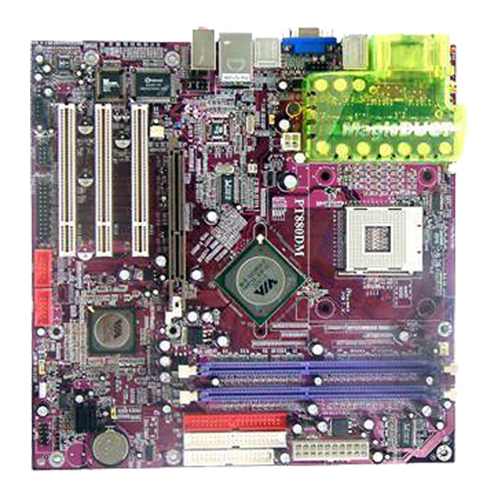
1-4 Layout Diagram & Jumper Setting PS/2 (for PM800DMS/PM880DMS Mouse /PT880DMS) Magic Duct LINE-IN LINE-OUT PS/2 USB1 USB Keyboard (JP4) CPU F.S.B. Frequency Selector CPU Socket SFAN2 K/B Power ON Jumper (JP1) CPU FAN Magic Duct DDR DIMM X2 PS2 KB/Mouse Port ATX Power Connector COM1 Connector VGA Connector... -
Page 10: Expansion Sockets
Jumpers Jumper Name Description Page JBAT CMOS RAM Clear 3-pin Block Keyboard Power On Enable/Disabled 3-pin Block JP2, JP5 USB Power On Enable/Disabled 3-pin Block CPU Front Side Bus Frequency Select 6-pin Block Connectors Connector Name Description Page ATXPWR ATX Power Connector 20-pin Block P.12 ATX12V... -
Page 11: Chapter 2 Hardware Installation
Chapter 2 Hardware installation 2-1 Pre-Hardware installation Before starting to use the computer with the motherboard installed the components on it, please make sure complete the following steps: To verify the jumper settings of your motherboard To install the CPU and Cooling Kits To install the system memory To install the expansion cards To connect with ribbon cables, panel wires, and power supply... -
Page 12: Cpu Clock
(2) Keyboard/USB Power On function Enabled/Disabled: JP1/JP2, JP5 When setting Enabled you can using keyboard by key in password/USB to power on system. 1-2 closed K/B Power ON Disable 2-3 closed K/B Power ON Enabled (Default) Keyboard Power On Setting 1-2 closed USB Power On Disable 2-3 closed... -
Page 13: To Install The Cpu
2-3 To install the CPU 3-1 Glossary Chipset (or core logic) - two or more integrated circuits which control the interfaces between the system processor, RAM, I/O devises, and adapter cards. Processor socket - the socket used to mount the system processor on the motherboard. Slot (AGP, PCI, ISA, RAM DIMMs) - the slots used to mount adapter cards and system RAM. -
Page 14: About Intel Pentium 4 478-Pin Cpu
2-3-2 About INTEL PENTIUM 4 478-PIN CPU This motherboard provides a 478-pin surface mount, Zero Insertion Force (ZIF) socket, referred to as the mPGA478B socket supports Intel Pentium 4 processor in the 478 Pin package utilizes Flip-Chip Pin Grid Array (FC-PGA2) package technology. The CPU that comes with the motherboard should have a cooling FAN attached to prevent overheating. -
Page 15: To Install The Expansion Cards
Generally speaking, installing DDR SDRAM modules to your motherboard is very easy, you can refer to figure 2-4 to see what a 184-Pin PC2100/PC2700/PC3200 DDR SDRAM module looks like. Figure 2-4 NOTE! When you install DIMM modules fully into the DIMM sockets the eject tab should be locked into the DIMM modules firmly and fit to its indention on both sides. -
Page 16: Assigning Irqs For Expansion Card
2-5-2 Assigning IRQs For Expansion Card Some expansion cards need to assign an IRQ address to operate. Generally speaking, an IRQ address must exclusively assign to one use only. With standard factory design, there are 16 IRQs available, but most of them are already in use. Standard Interrupt Assignments Priority Standard function... -
Page 17: Connectors And Pin Headers
This motherboard provides an AGP Slot, support the 4X/8X AGP VGA card. 2x notch 4x notch AGP SLOT 2-6 Connectors and pin headers 2-6-1 Connectors (1) Power Connector (20-pin block) : ATXPWR ATX Power Supply connector. This is a new defined 20-pins connector that usually comes with ATX case. - Page 18 The connectors for PS/2 keyboard and PS/2 Mouse. (4) USB Port connector: USB1, UL1 The connectors are 4-pin connector that connect USB devices to the system board. (5) LAN Port connector: LAN (only for PM800DMS/PM880DMS/PT880DMS) This connector is standard RJ45 connector for Network (6) Audio Connector: AUDIO This Connector are 3 phone Jack for LINE-OUT, LINE-IN, MIC.
- Page 19 IDE1 Pin 1 Primary IDE Connector (10) Secondary IDE Connector (40-pin block): IDE2 This connector connects to the next set of Master and Slave hard disks. Follow the same procedure described for the primary IDE connector. You may also configure two hard disks to be both Masters using one ribbon cable on the primary IDE connector and another ribbon cable on the secondary IDE connector.
-
Page 20: Pin Headers
2-6-2 Pin headers (1) Line-Out, MIC Header (9-pin): AUDIO This header connect to Front Panel Line-out, MIC connector with cable. Pin 1 AUDIO AUD - G ND AUD - MIC AUD - VCC AUD - MIC - BIAS AUD - FPO UT - R AUD - RET - R HP - O N AUD - FPO UT - L... - Page 21 (5) Reset switch lead: RESET This 2-pin connector connects to the case-mounted reset switch for rebooting your computer without having to turn off your power switch. This is a preferred method of rebooting in order to prolong the lift of the system’s power supply. See the figure below. (6) IDE Activity LED: HD LED This connector connects to the hard disk activity indicator light on the case.
- Page 22 (11) FAN Headers (3-pin) : SFAN1, SFAN2, CPUFAN These connectors support cooling fans of 350mA (4.2 Watts) or less, depending on the fan manufacturer, the wire and plug may be different. The red wire should be positive, while the black should be ground. Connect the fan’s plug to the board taking into consideration the polarity of connector.
-
Page 23: Starting Up Your Computer
2-7 Starting up your computer 1. After all connection are ready, close your computer case cover. 2. Be sure all the switches are off, and check that the power supply input voltage is set to proper position, usually in-put voltage is 220V∼240V or 110V∼120V depending on your country’s voltage used. -
Page 24: Chapter 3 Introducing Bios Settings
Chapter 3 Introducing BIOS Settings The BIOS is a program located on a Flash Memory of the motherboard. Using this program as a bridge between motherboard and operating system. When the computer starting to work, the BIOS program gain control. The BIOS first operates an auto-diagnostic test called POST (power on self test) for all the necessary hardware, it detects the entire hardware device and configures the parameters of the hardware synchronization. -
Page 25: Getting Help
3-2 Getting Help Main Menu The on-line description of the highlighted setup function is displayed at the bottom of the screen. Status Page Setup Menu/Option Page Setup Menu Press F1 to pop up a small help window that describes the appropriate keys to use and the possible selections for the highlighted item. - Page 26 Standard CMOS Features Use this Menu for basic system configurations. Advanced BIOS Features Use this menu to set the Advanced Features available on your system. Advanced Chipset Features Use this menu to change the values in the chipset registers and optimize your system’s performance.
-
Page 27: Standard Cmos Features
3-4 Standard CMOS Features The items in Standard CMOS Setup Menu are divided into several categories. Each category includes no, one or more than one setup items. Use the arrow keys to highlight the item and then use the <PgUp> or <PgDn> keys to select the value you want in each item. CMOS Setup Utility –... -
Page 28: Advanced Bios Features
3-5 Advanced BIOS Features CMOS Setup Utility – Copyright(C) 1984-2004 Award Software Advanced BIOS Features Virus Warning Disabled Item Help CPU L1 & L2 Cache Enabled CPU L3 Cache Enabled CPU L2 Cache ECC Checking Disabled Quick Power On Self Test Enabled Menu Level >... - Page 29 Quick Power On Self-Test This category speeds up Power On Self Test (POST) after you power on the computer. If this is set to Enabled. BIOS will shorten or skip some check items during POST. Enabled (default) Enable quick POST Disabled Normal POST First/Second/Third/Fourth Boot Device...
-
Page 30: Advanced Chipset Features
3-6 Advanced Chipset Features The Advanced Chipset Features Setup option is used to change the values of the chipset registers. These registers control most of the system options in the computer. CMOS Setup Utility – Copyright(C) 1984-2004 Award Software Advanced Chipset Features >... -
Page 31: Dram Timing Settings
3-6-1 DRAM Timing Settings CMOS Setup Utility – Copyright(C) 1984-2004 Award Software DRAM Timing Settings System Performance Auto By SPD Item Help RAS Active Time Menu Level >> RAS Precharge Time RAS to CAS Delay DRAM CAS Latency Bank Interleave Disabled DRAM Bus Select Auto... -
Page 32: Pci Timing Settings
3-6-3 PCI Timing Settings CMOS Setup Utility – Copyright(C) 1984-2004 Award Software PCI Timing Settings Item Help PCI Master 1 WS Write Disabled PCI Master 1 WS Read Disabled Menu Level >> CPU to CPI Post Write Enabled PCI Delay Transaction Enabled Vlink Mode Selection Mode 1... -
Page 33: Onchip Ide Function
3-7-1 OnChip IDE Function CMOS Setup Utility – Copyright(C) 1984-2004 Award Software OnChip IDE Function OnChip IDE Channel0 Enabled OnChip IDE Channel1 Enabled Item Help Primary Master Auto Primary Slave Auto Secondary Master PIO Auto Secondary Slave PIO Auto Primary Master UDMA Auto Menu Level >>... -
Page 34: Onchip Device Function
3-7-2 OnChip Device Function CMOS Setup Utility – Copyright(C) 1984-2004 Award Software OnChip Device Function VIA SATA Function Enabled Item Help VIA LAN Function Enabled Current VIA MAC Address is 003018-XXXXXX Menu Level >> VIA MAC Address Input Press Enter AC97 Sound Device Auto Game Port Address... - Page 35 Onboard Parallel Port 378/IRQ7 Parallel Mode Menu Level >> EPP Mode Select EPP1.7 ECP Mode Use DMA ↑↓→← Move Enter:Select +/-/PU/PD:Value F10:Save ESC:Exit F1:General Help F5:Previous Values F6:Optimized Defaults F7:Standard Defaults Onboard FDD Controller Select Enabled if your system has a floppy disk controller (FDD) installed on the system board and you wish to use it.
-
Page 36: Power Management Setup
the EPP function, the following message will be displayed on the screen: “EPP Mode Select.” At this time either EPP 1.7 spec. or EPP 1.9 spec. can be chosen. 3-8 Power Management Setup The Power Management Setup allows you to configure your system to most effectively save energy saving while operating in a manner consistent with your own style of computer use. -
Page 37: Wake Up Events
Power Button Function Pressing the power button for more than 4 seconds forces the system to enter the Soft-Off state. The settings are: Delay 4 Sec, Instant-Off. State After Power Failure This item allows the system power ON/OFF automatic when power loss and recovery again, you can choose Auto for recovery pre-state, or always ON/OFF after power recovery. -
Page 38: Pnp/Pci Configuration Setup
IRQ4 (COM 1) Enabled IRQ5 (LPT 2) Enabled Menu Level >>> IRQ6 (Floppy Disk) Enabled IRQ7 (LPT 1) Enabled IRQ8 (RTC Alarm) Disabled IRQ9 (IRQ2 Redir) Disabled IRQ10 (Reserved) Disabled IRQ11 (Reserved) Disabled IRQ12 (PS/2 Mouse) Enabled IRQ13 (Coprocessor) Disabled IRQ14 (Hard Disk) Enabled IRQ15 (Reserved) -
Page 39: Irq Resources
to “manual” choose specific resources by going into each of the sub menu that follows this field (a sub menu is preceded by a “>”). The settings are: Auto(ESCD), Manual. IRQ Resources When resources are controlled manually, assign each system interrupt a type, depending on the type of device using the interrupt. -
Page 40: Miscellaneous Control
↑↓→← Move Enter:Select +/-/PU/PD:Value F10:Save ESC:Exit F1:General Help F5:Previous Values F6:Optimized Defaults F7:Standard Defaults Shutdown Temperature This item can let users setting the Shutdown temperature, when CPU temperature over this setting the system will auto shutdown to protect CPU. Show PC Health in Post During Enabled, it displays information list below. -
Page 41: Load Standard/Optimized Defaults
DRAM Clock at next Boot is This field displays the capability of the memory modules that you can use The choice is either 100MHz or 133MHz or 166MHz or 200MHz. VAGP Output This item allows you to select 1.5V of the AGP 4X/8X VGA card. The choice are: 1.5V, 1.6V. -
Page 42: Chapter 4 Driver & Free Program Installation
system will boot and you can enter Setup freely. PASSWORD DISABLED. When a password has been enabled, you will be prompted to enter it every time you try to enter Setup. This prevents an unauthorized person from changing any part of your system configuration. -
Page 43: Via 4In1 Install Via Service Pack 4 In 1 Driver
SOUND install AC97 Audio Codec Installing driver install VIA LAN Controller driver (for PM800DMS/PM880DMS/PT880DMS) USB2.0 install USB 2.0 driver SATA install VIA Serial ATA driver PC-CILLIN install PC-CILLIN2004 anti-virus program PC-HEALTH install Winbond PC-HEALTH hardware monitor Software MBIOS&DX9 install BIOS Live Update Utility & Microsoft DirectX 9 driver 10. -
Page 44: Vga Install Via Pm800/Pm880 Vga Driver
5. Click NEXT to Install ATAPI Vender Support 6. Click NEXT to choose enabled DMA Mode Driver 7. Click NEXT to Install VIA AGP VXD Driver 8. Click NEXT to Install VIA IRQ Routing Mini port Driver 9. Click Finish to restart computer 4-2 VGA install VIA PM800/PM880 VGA Driver For WINDOWS 9X/ME/NT4.0/2000/XP... -
Page 45: Sound Install Via Ac97 Codec Audio Driver
3. Click NEXT to Install Driver File 4. Click Finish to Restart Computer 4-3 SOUND install VIA AC97’ Codec Audio Driver 1. Click SOUND when MAGIC INSTALL 2. Then auto detect operation system language MENU appears edition, click NEXT, start to install DRIVER 3. -
Page 46: Install Via Lan Controller Driver
7. Speaker configuration setting 8. 2-ch Speaker position test Note: The path of the file For WIN98/NT4.0/WIN2K/XP is X:\CODEC\VIACODEC\SETUP.EXE Note: In Win2K/WinME users have to click Control Panel\System\Device Manager\ DVD\CD-ROM drives to Enabled digital CD Audio for the CD-ROM Device when use the SPDIF-Out digital signal. -
Page 47: Magic Bios Install Bios Live Update Utility
In Windows 95/98 Winbond Hardware Doctor Monitoring Software needs some system files to copy in Utility that’s why it needs install PC-HEALTH twice to complete setup. 1. Click PC-Health when Magic Install Menu 2. Click OK when Winbond Hardware Doctor appears Setup Window appears 3. - Page 48 Click Magic BIOS when Magic Install Click Next to install the Magic BIOS in MENU appears Destination Folder After finish Setup you will have a Magic Double click the Magic BIOS icon you will BIOS icon in your screen have this picture, choose from internet you can upgrade BIOS On-line When On-line update BIOS the program Click Next if you need update BIOS, after...
-
Page 49: Pc-Cillin Install Pc-Cillin2004 Anti-Virus Program
When choose From Local Driver to update 10. Choose the correct BIOS file to update BIOS BIOS, you must have the correct BIOS file in your Local Driver PC-CILLIN Install PC-CILLIN 2004 Anti-virus program 1. Click PC-CILLIN when MAGIC INSTALL 2. -
Page 50: Usb2.0 Install Via Usb2.0 Device Driver
5. Click INSTALL, Start to install the software 6. Setup Complete and click FINISH 7. After PC-CILLIN 2004 complete, Please register your information and we recommend select update item to download newest engine code and virus code Note : Please install ACROBAT READER, Before you read PC-CILLIN 2004 User Manual, the path at X:\acrobat\adberdr6_enu_full.exe USB2.0 Install VIA USB2.0 DEVICE DRIVER 1. -
Page 51: Sata Install Via Serial Ata Driver
3. Select Install USB Driver and Click NEXT 4. Select FINISH and Restart your Computer 5. Check device working properly in Device Manager The Path of the file is X:\VIA\VIAUSB20\SETUP.EXE SATA Install VIA Serial ATA 1. Click SATA when MAGIC INSTALL MENU 2. -
Page 52: How To Disable On-Board Sound
STEP 1. Prepare a boot disc. (you may make one by click START click RUN type SYS A: click STEP 2. Copy utility program to your boot disc. You may copy from DRIVER CD X:\FLASH\AWDFLASH.EXE or download from our web site. STEP 3. Copy latest BIOS for PM800DM/PM800DMS/PM880DM/PM880DMS/PT880DM/... - Page 53 PT880DMS from our web site to your boot disc. STEP 4. Insert your boot disc into A:, start the computer, type “Awdflash A:\ PM800Axxx.BIN /SN/PY/CC/R” PM800Axxx.BIN is the file name of latest BIOS it can be PM800A3.BIN or PM800B2.BIN means don’t save existing BIOS data means renew existing BIOS data...
Need help?
Do you have a question about the PM800DM and is the answer not in the manual?
Questions and answers