Table of Contents
Advertisement
Quick Links
NF3AE Series User Manual
NO. G03-NF3AE-F
Revision: 1.0
Release date: June 28, 2017
Trademark:
* Specifications and Information contained in this documentation are furnished for information use only, and are
subject to change at any time without notice, and should not be construed as a commitment by manufacturer.
Advertisement
Table of Contents

Related Manuals for JETWAY NF3AE Series


Summary of Contents for JETWAY NF3AE Series
- Page 1 NF3AE Series User Manual NO. G03-NF3AE-F Revision: 1.0 Release date: June 28, 2017 Trademark: * Specifications and Information contained in this documentation are furnished for information use only, and are subject to change at any time without notice, and should not be construed as a commitment by manufacturer.
- Page 2 Environmental Protection Announcement Do not dispose this electronic device into the trash while discarding. To minimize pollution and ensure environment protection of mother earth, please recycle.
-
Page 3: Table Of Contents
TABLE OF CONTENT ENVIRONMENTAL SAFETY INSTRUCTION ................iv USER’S NOTICE ........................v MANUAL REVISION INFORMATION ..................v CHAPTER 1 INTRODUCTION OF THE MOTHERBOARD FEATURE OF MOTHERBOARD ................1 SPECIFICATION ......................2 LAYOUT DIAGRAM ....................3 CHAPTER 2 HARDWARE INSTALLATION JUMPER SETTING ..................... 9 CONNECTORS AND HEADERS ................ -
Page 4: Environmental Safety Instruction
Environmental Safety Instruction Avoid the dusty, humidity and temperature extremes. Do not place the product in any area where it may become wet. 0 to 60 centigrade is the suitable temperature. (The figure comes from the request of the main chipset) ... -
Page 5: User's Notice
USER’S NOTICE COPYRIGHT OF THIS MANUAL BELONGS TO THE MANUFACTURER. NO PART OF THIS MANUAL, INCLUDING THE PRODUCTS AND SOFTWARE DESCRIBED IN IT MAY BE REPRODUCED, TRANSMITTED OR TRANSLATED INTO ANY LANGUAGE IN ANY FORM OR BY ANY MEANS WITHOUT WRITTEN PERMISSION OF THE MANUFACTURER. -
Page 6: Chapter 1 Introduction Of The Motherboard Feature Of Motherboard
Chapter 1 Introduction of the Motherboard Feature of Motherboard ® Onboard Intel Bay Trail Series Processor, with low power consumption never denies high performance Support single channel DDR3L 1333 MHz SODIMM, up to 8GB Support 1 * SATAII device ... -
Page 7: Specification
Specification Spec Description 3.5”SBC; 6 layers; PCB size: 14.8x 10.2 cm Design ® Intel Bay Trail-D/M/I series CPU Embedded *CPU model varies from different IPC options. Please consult your dealer for more information of onboard CPU. 1 * DDRIIIL SODIMM Slot for un-buffered Single Channel Memory Slot DDRIIIL 1333 MHz SDRAM, up to 8GB ... -
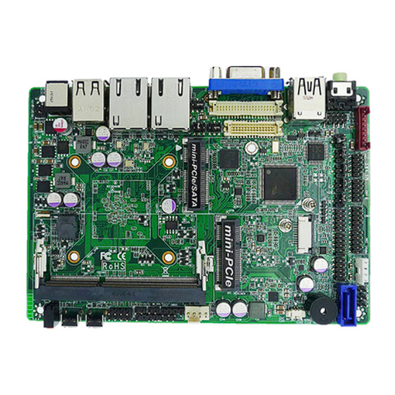
Page 8: Layout Diagram
4* Serial port header 2* 9-pin USB 2.0 header (Expansible to 4* USB 2.0 ports) 1* GPIO header 1* SM_BUS header 1* PS2KBMS header 1* Front panel header 2* LAN LED activity header ... - Page 9 Internal Diagram-Front Side: Serial Port Header (COM4/3/2/1) INVERTER SATA Front Panel Power Connector Audio Header SATAII Port Line-Out Port GPIO Header USB 2.0 Header USB 3.0 Port Over USB 2.0 Port SPDIF Out Header Half-size Mini-PCIE Slot VGA Port LVDS Header EDP Header CPUFAN Header SMBUS Header...
- Page 10 Internal Diagram-Back Side: Intel CPU...
-
Page 11: Jumper Position
Jumper Position: COPEN AT-MODE JBAT... - Page 12 Jumper Jumper Name Description LVDS LCD VCC 3.3V/5V/12V Select 4-Pin Block LVDS INVERTER VCC 5V/12V/Adapter 4-Pin Block VCC Select eDP LCD VCC 3.3V/5V/12V Select 4-Pin Block eDP Backlight VCC 5V/12V/ Adapter VCC 4-Pin Block Select COM4 Header Pin9 Function Select 4-Pin Block COM3 Header Pin9 Function Select 4-Pin Block...
- Page 13 Headers Header Name Description FP_AUDIO Front Panel Audio Header 9-pin Block SPDIFOUT SPDIF Out Header 2-pin Block COM1/2/3/4 Serial Port Header X4 9-pin Block GPIO GPIO Header 10-pin Block USB3/ USB4 USB 2.0 Header 9-pin Block SMBUS SMBUS Header 4-pin Block PS2KBMS PS2KBMS Header 6-pin Block...
-
Page 14: Chapter 2 Hardware Installation
Chapter 2 Hardware Installation 2-1 Jumper Setting (1) JP1 (4-pin): LVDS LCD VCC 3.3V/5V/12V Select JP1→LVDS LCD VCC 2-4 Closed: LVDS 3-4 Closed: LVDS 4-6 Closed: LVDS LCD VCC= 3.3V; LCD VCC= 5V; LCD VCC= 12V. (2) JP2 (4-pin): LVDS INVERTER VCC 5V/12V/Adapter VCC Select JP2→LVDS Inverter VCC 2 4 6 2 4 6... - Page 15 (3) JP8 (4-pin): eDP LCD VCC 3.3V/5V/12V Select JP8→eDP LCD VCC 2-4 Closed: eDP 3-4 Closed: eDP 4-6 Closed: eDP LCD VCC= 3.3V; LCD VCC= 5V; LCD VCC= 12V. (4) JP9 (4-pin): eDP Backlight VCC 3.3V/5V/Adapter VCC Select JP9→eDP Backlight VCC 2-4 Closed: eDP 3-4 Closed: eDP 4-6 Closed:...
- Page 16 (5) JP3 (4-pin): COM4 Header Pin9 Function Select JP3→COM4 2 4 6 2 4 6 1 3 5 1 3 5 2-4 Closed: 3-4 Closed: 4-6 Closed: RI=RS232; RI= 5V; RI= 12V. (6) JP4 (4-pin): COM3 Header Pin9 Function Select JP4→COM3 2 4 6 2 4 6...
- Page 17 (7) JP5 (4-pin): COM2 Header Pin9 Function Select JP5→COM2 2 4 6 2 4 6 1 3 5 1 3 5 2-4 Closed: 3-4 Closed: 4-6 Closed: RI=RS232; RI= 5V; RI= 12V. (8) JP6 (4-pin): COM1 Header Pin9 Function Select JP6→COM1 2 4 6 2 4 6...
- Page 18 (9) JBAT (2-pin): Clear CMOS JBAT 1-2 Open: Normal; 1-2 Closed:Clear CMOS CMOS Clear Setting (10)COPEN (2-pin): Case Open Message Display Function Select COPEN Case open function Pin 1-2 Closed: When Case open function pin short to GND, the Case open function was detected.
- Page 19 (11)AT_MODE (2-pin): AT Mode Function Select Pin 1-2 closed: AT_MODE function is enabled. In this case your computer will automatically turns on after a sudden power failure when power supply resumes. AT_MODE 1-2 Open: ATX Mode Selected; 1-2 Closed: AT Mode Selected (12)JP7 (2-pin): Security Measure Function Select 1-2 Open:Enable Security Measures in the Flash Descriptor(Default);...
-
Page 20: Connectors And Headers
Connectors and Headers 2-2-1 Connectors (1) Rear I/O Connectors RJ-45 LAN Ports USB 2.0 Port VGA Port DC Jack Line-Out Port USB 3.0 Port USB 2.0 Ports (2) SATA1(7-pin): SATAII Port connector SATA1 port is a high-speed SATAII port that supports 3GB/s transfer rate. Pin No. - Page 21 (3) PWOUT (4-pin): SATA Power Connector Pin 1 (4) CPUFAN (4-pin): CPUFAN Connector CPUFAN1 Control Fan Clock Pin1...
-
Page 22: Headers
(5) INVERTER (8-pin): LVDS Inverter Connector Pin No. Definition Backlight Enable Backlight PWM PVCC PVCC Backlight Up SW Pin 1 Backlight Down SW 2-2-2 Headers (1) FP_AUDIO (9-pin): Line-Out, MIC-In Header This header connects to Front Panel Line-out, MIC-In connector with cable. Pin 1 MIC-R MIC-L... - Page 23 (2) SPDIFOUT (2-pin): SPDIF Out Header SPDIFOUT Pin1 (3) COM4/3/2/1 (9-pin): Serial Port Headers Pin NO. RS232 *RS422 *RS485 (for COM1) (for COM1) Pin 1 DATA- Pin 2 DATA+ Pin 3 Pin 4 Pin 5 Pin 6 Pin 7 Pin 8 Pin 9 *Notice: RS422, RS485 function is supported by COM1 header only, with compatible COM cable for RS422 or RS 485 function.
- Page 24 (4) GPIO (10-pin): GPIO Header Pin 1 (5) USB2/USB4 (9-pin): USB 2.0 Port Header Pin 1...
- Page 25 (6) SMBUS (4-Pin): SM BUS Header SMBUS_DATA SMBUS_CLK Pin 1 (7) PS2KBMS (6-pin): PS/2 Keyboard & Mouse Header MS_DATA MS_CLK KB_CLK KB_DATA Pin 1...
- Page 26 (8) FP: (8-pin) Front Panel Header PWRBTN RSTSW PWRLED - HDDLED- PWRLED+ HDDLED+ Pin 1 (9)LAN1LED/LAN2LED (2-pin): LAN Activity LED Headers LED- Pin1 LED+ LAN1LED/LAN2LED...
- Page 27 (10) LVDS (30-pin): 24-bit Dual Channel LVDS Header Pin2 Pin 1 Pin NO. Pin Define Pin NO. Pin Define Pin 1 LVDSB_DATAN3 Pin 2 LVDSB_DATAP3 Pin 3 LVDS_CLKBN Pin 4 LVDS_CLKBP Pin 5 LVDSB_DATAN2 Pin 6 LVDSB_DATAP2 Pin 7 LVDSB_DATAN1 Pin 8 LVDSB_DATAP1 Pin 9...
- Page 28 (10) eDP (40-pin): eDP Header Pin 1 Pin21 Pin NO. Pin Define Pin NO. Pin Define Pin 1 Pin 21 Pin 2 Pin 22 Pin 3 Lane3_N Pin 23 Pin 4 Lane3_P Pin 24 Pin 5 Pin 25 Pin 6 Lane2_N Pin 26 Pin 7...
-
Page 29: Chapter 3 Introducing Bios
Chapter 3 Introducing BIOS Notice! The BIOS options in this manual are for reference only. Different configurations may lead to difference in BIOS screen and BIOS screens in manuals are usually the first BIOS version when the board is released and may be different from your purchased motherboard. Users are welcome to download the latest BIOS version form our official website. -
Page 30: Bios Menu Screen
BIOS Menu Screen The following diagram show a general BIOS menu screen: Menu Bar BIOS Menu Screen General Help Items Current Setting Value Menu Items Function Keys... -
Page 31: Function Keys
Function Keys In the above BIOS Setup main menu of, you can see several options. We will explain these options step by step in the following pages of this chapter, but let us first see a short description of the function keys you may use here: ... -
Page 32: Memu Bars
3-5 Menu Bars There are six menu bars on top of BIOS screen: Main To change system basic configuration Advanced To change system advanced configuration Chipset To change chipset configuration Security Password settings Boot To change boot settings Save & Exit Save setting, loading and exit options. -
Page 33: Main Menu
Main Menu Main menu screen includes some basic system information. Highlight the item and then use the <+> or <-> and numerical keyboard keys to select the value you want in each item. System Date Set the date. Please use [Tab] to switch between date elements. System Time Set the time. -
Page 34: Advanced Menu
3-7 Advanced Menu OS Selection The optional settings: [Linux/Android]; [Windows 8.X]; [Windows 7]. In the case that OS selection is set as [Windows 7], XHCI & EHCI mode will be auto configuration. *Note: User need to go to this item to select the OS mode before installing corresponding OS driver, otherwise problems will occur when installing the driver. - Page 35 ACPI Sleep State Use this item to select the highest ACPI sleep state the system will enter when the suspend button is pressed. The optional settings are: [Suspend Disabled]; [S3 (Suspend to RAM)]. Wake-up Function Settings Press [Enter] to make settings for the following sub-items: Wake-up System with Fixed Time Use this item to enable or disable system wake on alarm event.
- Page 36 Serial Port 1 Configuration Press [Enter] to make settings for the following items: Serial Port Use this item to enable or disable serial port (COM). Change Settings Use this item to select an optimal setting for super IO device. optional settings are:...
- Page 37 Serial Port 3 Configuration Press [Enter] to make settings for the following items: Serial Port Use this item to enable or disable serial port (COM). Change Settings Use this item to select an optimal setting for super IO device. optional settings are:...
- Page 38 [Enabled], the following sub-items shall appear: WatchDog Timer Value User can set a value in the range of 4 to 255. WatchDog Timer Unit The optional settings are: [Sec.]; [Min.]. WatchDog Wake-up Timer in ERP This item support WDT wake-up while ERP function is set as [Auto]. The optional settings are: [Disabled];...
- Page 39 The optional settings are: [Disabled]; [Enabled]. When set as [Enabled], the following sub-items shall appear: CPUFAN Full-Speed Temperature Use this item to set CPUFAN full speed temperature. Fan will run at full speed when above the pre-set temperature. CPUFAN Full-Speed Duty Use this item to set CPUFAN full speed duty.
- Page 40 The optional settings are: [VT100]; [VT100+]; [VT-UTF8]; [ANSI]. Bits per second The optional settings are: [9600]; [19200]; [38400]; [57600]; [115200]. Data Bits The optional settings are: [7]; [8]. Parity The optional settings are: [None]; [Even]; [Odd]; [Mark]; [Space]. Stop Bits The optional settings are: [1];...
- Page 41 The optional setting is: [COM1]. Serial Port for Out-of-Band Management/ Windows Emergency Management Services (EMS) Console Redirection The optional settings are: [Disabled]; [Enabled]. When set as [Enabled], user can make further settings in ‘Console Redirection Settings’: Console Redirection Settings The settings specify how the host computer and the remote computer (which the user is using) will exchange data.
- Page 42 Press [Enter] to view current CPU configuration and make settings for the following sub-items: Limit CPUID Maximum The optional settings: [Disabled]; [Enabled]. This item should be set as [Disabled] for Windows XP. Execute Disable Bit The optional settings: [Disabled]; [Enabled]. Hardware Prefetcher The optional settings are: [Disabled];...
- Page 43 The optional settings are: [Enabled]; [Disabled]. mSATA The optional settings are: [Enabled]; [Disabled]. Network Stack Configuration Press [Enter] to go to ‘Network Stack’ screen to make further settings. Network Stack The optional settings are: [Disabled]; [Enabled]. When set as [Enabled], the following sub-items shall appear: Ipv4 PXE Support The optional settings are: [Disabled];...
- Page 44 The optional settings are: [UEFI first]; [Legacy Only]. USB Configuration Press [Enter] to make settings for the following sub-items: USB Configuration Legacy USB Support The optional settings are: [Enabled]; [Disabled]; [Auto]. [Enabled]: To enable legacy USB support. [Disabled]: To keep USB devices available only for EFI specification, [Auto]: To disable legacy support if no USB devices are connected.
-
Page 45: Chipset Menu
Select [Manual] you can set value for the following sub-item: ‘Device Power-up delay in seconds’. Device Power-up delay in seconds The delay range is from 1 to 40 seconds, in one second increments. Reltek PCIe GBE Family Controller (MAC:XX:XX:XX:XX:XX:XX) Use this item to get driver information and configure Realtek ethernet controller parameter. - Page 46 North Bridge Press [Enter] to view current using memory information and make settings for the following sub-items: Intel IGD Configuration PAVC Use this item to enable or disable Protected Audio Video control. The optional settings are: [Disabled]; [LITE Mode]; [SERPENT Mode]. DVMT Pre-Allocated Use this item to select DVMT 5.0 Pre-Allocated (Fixed) Graphics Memory size used by the Internal Graphics Device.
- Page 47 The optional setting are: [800 x 480 24bit Single]; [800x 600 18bit Single]; ; [800x 600 24bit Single]; [1024 x 600 18bit Single]; [1024 x 768 18bit Single]; [1024 x 768 24bit Single]; [1280 x 768 24bit Single]; [1280 x 800 18bit Single]; [1280 x 800 24bit Single];...
-
Page 48: Security Menu
Onboard Lan1 Controller The optional settings are: [Enabled]; [Disabled]. Onboard Lan2 Controller The optional settings are: [Enabled]; [Disabled]. System State after Power Failure Use this item to select AC power state when power is re-applied after a power failure. The optional settings are: [Always Off]; [Always On]; [Former State]. 3-9 Security Menu Security menu allow users to change administrator password and user password settings. -
Page 49: Boot Menu
3-10 Boot Menu Boot Configuration Setup Prompt Timeout Use this item to set number of seconds to wait for setup activation key. Bootup Numlock State Use this item to select keyboard numlock state. The optional settings are: [On]; [Off]. Quiet Boot The optional settings are: [Disabled];... -
Page 50: Save & Exit Menu
Boot Option Priorities Boot Option The optional settings are: [UEFI: Built-in EFI Shell]; [Disabled]. 3-11 Save & Exit Menu Save Changes and Reset This item allows user to reset the system after saving the changes. - Page 51 Discard Changes and Reset This item allows user to reset the system without saving any changes. Restore Defaults Use this item to restore /load default values for all the setup options. Save as User Defaults Use this item to save the changes done so far as user defaults. Restore User Defaults Use this item to restore defaults to all the setup options.
Need help?
Do you have a question about the NF3AE Series and is the answer not in the manual?
Questions and answers