Table of Contents
Advertisement
Quick Links
Advertisement
Table of Contents

Related Manuals for Brymen BM236R


Summary of Contents for Brymen BM236R
- Page 1 USER'S MANUAL BM236R BM237R BM239R...
- Page 2 1) SAFETY This manual contains information and warnings that must be followed for operating the meter safely and maintaining the meter in a safe operating condition. If the meter is used in a manner not specified by the manufacturer, the protection provided by the meter may be impaired.
-
Page 3: Cenelec Directives
International Electrical Symbols Marking of Electrical and Electronic Equipment (EEE). Do not dispose of this product as unsorted municipal waste. Contact a qualified recycler Caution! Refer to the explanation in this Manual Caution! Possibility of electric shock Earth (Ground) Meter protected throughout by Double Insulation or Reinforced insulation Fuse Direct Current (DC) Alternating Current (AC) -
Page 4: Product Description
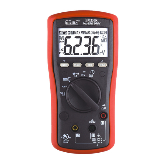
3) PRODUCT DESCRIPTION Note: Top of the line model is used as representative for illustration purposes. Please refer to your respective model for function availability. 1) 3-5/6 digits 6000 counts LCD display 2) Push-buttons for special functions & features 3) Selector to turn the Power On or Off and Select a function 4) Input Jack for 10A (20A for... -
Page 5: Operation Caution
True RMS RMS (Root-Mean-Square) is a term used to describe the effective or equivalent DC value of an AC signal. True RMS is the term which identifies a DMM that responds accurately to the effective RMS value regardless of the waveforms such as: square, sawtooth, triangle, pulse trains, spikes, as well as distorted waveforms with the presence of harmonics. - Page 6 AutoV (LoZ) mode AutoV automatically selects measurement function of DCV or ACV, based on their input levels via the test leads. The input also provides a low ramp-up impedance (LoZ) to drain ghost voltages*. ●With no input, the meter displays “- - - -” when it is ready. ●When a signal above the voltage threshold of 1V DC or AC up to the rated 1000V is present, the meter displays the voltage value in appropriate DC or AC, whichever larger in peak magnitude.
- Page 7 WARNING: AutoV mode input impedance increases abruptly from initial 2.1kΩ to a few hundred kΩ’s on high voltage hard signals. “LoZ” displays on the LCD to remind the users of being in such low impedance mode. Peak initial load current, while probing 1000VAC for example, can be up to 673mA (1000V x 1.414 / 2.1kΩ), decreasing abruptly to approx.
- Page 8 Line Frequency functions (Models 237R & 239R only) Press the Hz push-button momentarily to toggle Hz function. It is only available to Voltage and Current related ranges. Input sensitivity varies automatically with the function range selected while activating the Hz function.
- Page 10 BeepLit Continuity function is having improved convenience for checking wiring connections and operation of switches. A continuous beep tone together with flashing display backlight indicate a complete wire. Such audible and visible indications improve continuity readabilities in noisy working environments. In Diode function, the normal forward voltage drop (forward biased) for a good silicon diode is between 0.400V to 0.900V.
- Page 11 A Current function (Models 237R & 239R only) Press SELECT button momentarily to toggle between DC and AC. Last selection will be saved as power up default for repeat measurement convenience.
- Page 12 A Current function (Models 239R only) Press SELECT button momentarily to toggle between DC and AC. Last selection will be saved as power up default for repeat measurement convenience. Application notes for flame sensors: DCA function is useful for HVAC/R flame sensor applications. The 0.1A resolution can identify the minute current changes in flame detector applications.
- Page 13 Temperature over 165 F (74 C) at photocell For gas flames (Flame Rod): Ignition interference (A flame signal current difference with the ignition both on and off greater than 0.5A indicates the presence of ignition interference) Insufficient ground (must be at least 4 times the detector area) ...
- Page 14 & 3-Phase Rotation function Inputs are made via the test lead terminals L1/L2/L3. Phase Rotation directions are indicated as symbolic movements by the LCD segments. Press SELECT button momentarily toggles between modes. Last selection will be saved as power up default for repeat measurement convenience.
- Page 15 CAUTION Proper Rotation detection relies on solid signal connection to all three test lead terminals simultaneously. Any single disconnection will lead to detection failure and may produce false indication. To verify signal connection and hence proper meter indication, swap any two connects (to the meter) to check for meter indication of reverse movement Using the Hi-sensitivity mode for Motors:...
-
Page 16: Maintenance Warning
Hold The hold feature freezes the display for later view. Press the HOLD button momentarily to toggle the hold feature. Relative Zero ( ) mode Relative Zero allows the user to offset the meter consecutive measurements with the displaying reading as the reference value. Practically all displaying readings can be set as relative reference value including MAX/MIN/AVG feature readings. -
Page 17: General Specification
Cleaning and Storage Periodically wipe the case with a damp cloth and mild detergent; do not use abrasives or solvents. If the meter is not to be used for periods of longer than 60 days, remove the battery and store it separately Trouble Shooting If the instrument fails to operate, check battery, fuse, leads, etc., and replace as necessary. - Page 18 Altitude: Operating below 2000m Storage Temperature: -20 C ~ 60 C, < 80% R.H. (with battery removed) Temperature Coefficient: Nominal 0.15 x (specified accuracy)/ C @ (-10 C ~ 18 C or 28 ~ 45 C), or otherwise specified Sensing: True RMS sensing Ingress Protection: IP40 Pollution Degree: 2 Safety: Certified per IEC/UL/EN61010-1 Ed.
- Page 19 Electrical Specification Accuracy is given as (% of reading digits + number of digits) or otherwise specified @ 23 5 ACV & ACA accuracies are specified from 1 % to 100 % of range or otherwise specified. Maximum Crest Factor <2:1 at full scale & <4:1 at half scale, and with frequency components fall within the meter specified frequency bandwidth for non-sinusoidal waveforms AC Voltage...
- Page 20 VFD_ACV (with Low Pass Filter ) RANGE Accuracy 10Hz ~ 100Hz (fundamental) 600.0V, 1000V 1.0%+3d 100Hz ~ 400Hz (fundamental) 600.0V, 1000V 10%+3d Not specified for fundamental frequency > 400Hz Accuracy linearly decreases from 1% + 3d @100Hz to 10% + 3d @400Hz AutoV_ACV RANGE Accuracy...
- Page 21 25k @ 9Vdc 13k @ 10Vdc 2.6k @ 50Vdc At direct input >>50V (typical) from quiescence: Initial impedance is approximately 2.3k. Impedance increases abruptly within a fraction of a second as display voltage (hard signal) is much higher than 50V (typical).
- Page 22 Diode Tester RANGE Accuracy 3.000V 0.9% + 2d Test Current: 0.3mA typical Open Circuit Voltage: < 3.2VDC typical DCA & ACA (Model 239R only) RANGE Accuracy Burden Voltage DCA 0.7% + 3d 200.0A, 2000A 2.5mV/A ACA (50H ~ 400H 1.0% + 3d 200.0A, 2000A 2.5mV/A Combination PTC protective impedance is being used...
- Page 23 Line Frequency (Models 237R & 239R only) Function Sensitivity (Sine RMS) Range 60mV, 600mV 50mV 10Hz - 50kHz 10Hz - 50kHz 10Hz - 50kHz 600V 10Hz - 1kHz 1000V 500V 10Hz - 1kHz VFD 600V 10Hz - 1kHz VFD 1000V 500V 10Hz - 1kHz 10Hz - 5kHz...
-
Page 24: Limited Warranty
BRYMEN TECHNOLOGY CORPORATION. BRYMEN assumes no risk for damage in transit. BRYMEN will, at its option, repair or replace the defective product free of charge. However, if BRYMEN determines that the failure was caused by misused, altered, neglected, or damaged by accident or abnormal conditions of operation or handling, you will be billed for the repair.
Need help?
Do you have a question about the BM236R and is the answer not in the manual?
Questions and answers