Advertisement
Advertisement
Table of Contents

Related Manuals for Brymen BM821s


Summary of Contents for Brymen BM821s
- Page 1 USER'S MANUAL BM821s, BM822s, BM827s, BM829s BM521s, BM525s...
- Page 2 1) SAFETY Terms in this manual WARNING identifies conditions and actions that could result in serious injury or even death to the user. CAUTION identifies conditions and actions that could cause damage or malfunction in the instrument. This manual contains information and warnings that must be followed for operating the instrument safely and maintaining the instrument in a safe operating condition.
-
Page 3: International Electrical Symbols
WARNING To reduce the risk of fire or electric shock, do not expose this product to rain or moisture. To avoid electrical shock hazard, observe the proper safety precautions when working with voltages above 60 VDC or 30 VAC rms. These voltage levels pose a potential shock hazard to the user. -
Page 4: Product Description
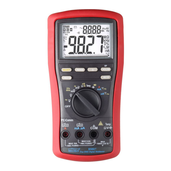
3) PRODUCT DESCRIPTION Note: Top of the line model is used as representative for illustration purposes. Please refer to your respective model for function availability. 1) 4 digits 9999 counts dual displays 2) Push-buttons for special functions & features 3) Selector to turn the Power On or Off and Select a function 4) Input Jack for 10A (20A for 30sec) current function... - Page 5 Average sensing RMS calibrated RMS (Root-Mean-Square) is the term used to describe the effective or equivalent DC value of an AC signal. Most digital multimeters use average sensing RMS calibrated technique to measure RMS values of AC signals. This technique is to obtain the average value by rectifying and filtering the AC signal.
-
Page 6: Operation
4) OPERATION CAUTION Before and after hazardous voltage measurements, test the voltage function on a known source such as line voltage to determine proper meter functioning. AutoCheck mode (Models 525s, 521s, 829s only) This innovative AutoCheck feature automatically selects measurement function of DCV, ACV or Resistance () based on the input via the test leads. - Page 7 *As Hazardous-Alert: When making resistance measurements in AutoCheck mode, an unexpected display of voltage readings alerts you that the object under test is being energized. *Ghost-voltage Buster: Ghost-voltages are unwanted stray signals coupled from adjacent hard signals, which confuse common multimeter voltage measurements. Our AutoCheck mode provides low (ramp-up) input impedance (approx.
- Page 8 measurements normally set the most appropriate trigger level. You can also press the RANGE button momentarily to select another trigger level (voltage range) manually. If the Hz reading becomes unstable, select higher voltage range to avoid electrical noise. If the reading shows zero, select lower voltage range.
- Page 9 ACmV , dBm (Model 829s only), Hz functions +ACmV Press the SELECT button momentarily to select the subject functions in sequence. Last selection will be saved as power up default for repeat measurement convenience.
- Page 10 nS Conductance (Models 525s, 521s, 829s, 827s only), Resistance, Continuity functions Press the SELECT button momentarily to select the subject functions in sequence for models 525s, 521s, 829s and 827s. Last selection will be saved as power up default for repeat measurement convenience.
- Page 11 Capacitance, Diode test functions Press the SELECT button momentarily to select the subject functions in sequence. Last selection will be saved as power up default for repeat measurement convenience. CAUTION Discharge capacitors before making any measurement. Large value capacitors should be discharged through an appropriate resistance load.
- Page 12 Normal forward voltage drop (forward biased) for a good silicon diode is between 0.400V to 0.900V. A reading higher than that indicates a leaky diode (defective). A zero reading indicates a shorted diode (defective). An OL indicates an open diode (defective). Reverse the test leads connections (reverse biased) across the diode.
- Page 13 PC computer interface capabilities The instrument equips with an optical isolated interface port at the meter back for data communication. Optional purchase PC USB interface kit BU-82X is required to connect the meter to the PC computer. MAX/MIN/AVG* (REC) at fast 20/s measurement mode (Models 525s*, 521s*, 829s, 827s only)
- Page 14 Beep-Jack™ Input Warning The meter beeps as well as displays “InEr” to warn the user against possible damage to the meter due to improper connections to the A, mA, or A input jacks when other function (like voltage function) is selected. Beep-Jack Input Warning is disabled while Data Logging operation (Models 525s &...
- Page 15 ●Press the (Timer) button for 1 second or more to display the selected sampling speed in second. Factory default t0.05 means sampling speed is 0.05 second. Press the (Up-arrow) or (Down-arrow) button momentarily to select a different sampling speed from 0.05s (0.1s for single T1/T2, Diode & /nS; 0.5s for Hz/Duty; 2s for Cx & dual T1 /T1-T2 ), 0.1s, 0.5s, 1s, 2s, 3s, 4s, 5s, 10s, 15s, 30s, 60s, 120s, 180s, 300s, up to the slowest 600s.
- Page 16 session-page(s), and start a new logging session from the very first session-page (P.001) with maximum meter memory. ●The bar-graph turns to a swinging pointer when data-logging mode is running. ●Press SELECT button momentarily to toggle the LCD display between measuring data and logged data item number (mini / main displays for most-significant / least-significant numbers separately).
-
Page 17: Maintenance
another session-page in sequence. Press-and-hold for 1 second and up for fast scrolling, and the beeper sounds when the first or last page is reached. ●Turn Rotary switch to another function or OFF to exit the RECALL mode. 5) MAINTENANCE WARNING To avoid electrical shock, disconnect the meter from any circuit, remove the test leads from the input jacks and turn OFF the meter before opening the case. - Page 18 Cleaning and Storage Periodically wipe the case with a damp cloth and mild detergent; do not use abrasives or solvents. If the meter is not to be used for periods of longer than 60 days, remove the battery and store it separately Trouble Shooting If the instrument fails to operate, check battery, fuses, leads, etc., and replace as necessary.
-
Page 19: General Specifications
11A/1000Vac & Vdc, IR 20kA or better, F fuse; Dimension: 10 x 38 mm Battery replacement: Loosen the 2 screws from the battery access door of the case bottom. Lift the battery access door and thus the battery compartment up. Replace the battery. Re-fasten the screws. - Page 20 Overload Protections: A & mA : 0.44A/1000V DC/AC rms, IR 10kA, F fuse : 11A/1000V DC/AC rms, IR 20kA, F fuse : 1100V DC/AC rms mV, & Others : 1000V DC/AC rms E.M.C. : Meets EN61326-1:2006 (EN55022, EN61000-3-2, EN61000-3-3, EN61000-4-2, EN61000-4-3, EN61000-4-4, , EN61000-4-5, EN61000-4-6, EN61000-4-8, EN61000-4-11) In an RF field of 3V/m: Capacitance function is not specified...
- Page 21 DC Voltage Input Impedance: 10M, 50pF nominal Function RANGE Accuracy Selectable reference impedance of 4, 8, 60.00mV 0.12%+2d 16, 32, 50, 75, 93, 110, 125, 135, 150, 200, 600.0mV 0.06%+2d 250, 300, 500, 600, 800, 900, 1000, 1200 9.999V, 99.99V, 0.08%+2d AutoCheck (DCV)
- Page 22 for 1kHz ~ 15kHz only Open Circuit Voltage: < 1.2VDC (< Input Impedance: 10M, 50pF nominal 1.0VDC for 60M range) (80pF nominal for mV ranges) Audible Continuity Tester AutoCheck (ACV) Audible threshold: between 20 and 300; RANGE Accuracy Response time < 100s 50Hz ~ 60Hz Capacitance 9.999V, 99.99V, 999.9V...
- Page 23 interval Specified Frequency: 5Hz ~ 10kHz Non-Contact EF-Detection DC Current Typical Voltage Bar Graph RANGE Accuracy Burden voltage Indication 20V (tolerance:10V~36V) 600.0A, 0.08mV/A 55V (tolerance: 23V ~ 83V) 6000A 110V (tolerance: 59V ~ 165V) 60.00mA, 0.2%+4d 2.1mV/mA 220V (tolerance: 124V ~ 330V) ---- 600.0mA 440V (tolerance: >...
-
Page 24: Limited Warranty
BRYMEN TECHNOLOGY CORPORATION. BRYMEN assumes no risk for damage in transit. BRYMEN will, at its option, repair or replace the defective product free of charge. However, if BRYMEN determines that the failure was caused by misused, altered, neglected, or damaged by accident or abnormal conditions of operation or handling, you will be billed for the repair.
Need help?
Do you have a question about the BM821s and is the answer not in the manual?
Questions and answers