Table of Contents
Advertisement
Quick Links
Instructions – Parts List
Parts
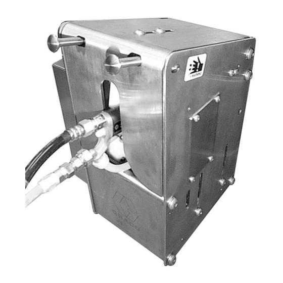
Gun Flush Boxt Module
100 psi (0.7 MPa, 7 bar) Maximum Air Inlet Pressure
Part No. 570046
Read warnings and instructions.
See page 2 for Table of Contents.
GRACO INC. P.O. BOX 1441 MINNEAPOLIS, MN 55440-1441
Copyright 1998, Graco Inc. is registered to I.S. EN ISO 9001
684019 rev.G
Advertisement
Table of Contents

Related Manuals for Graco Gun Flush Box 570046


Summary of Contents for Graco Gun Flush Box 570046
- Page 1 100 psi (0.7 MPa, 7 bar) Maximum Air Inlet Pressure Part No. 570046 Read warnings and instructions. See page 2 for Table of Contents. GRACO INC. P.O. BOX 1441 MINNEAPOLIS, MN 55440-1441 Copyright 1998, Graco Inc. is registered to I.S. EN ISO 9001...
-
Page 2: Table Of Contents
......Graco Standard Warranty ..... . -
Page 3: Warnings
WARNING FIRE, EXPLOSION, AND ELECTRIC SHOCK HAZARD Improper grounding, poor air ventilation, open flames, or sparks can cause a hazardous condition and result in fire, explosion, or electric shock, which can result in serious injury. D Ground the equipment and the object being sprayed. See Grounding on page 7. D Provide fresh air ventilation to avoid the buildup of flammable fumes from solvent or the fluid being sprayed. - Page 4 D This equipment is for professional use only. D Read all instruction manuals, tags, and labels before operating the equipment. D Use the equipment only for its intended purpose. If you are uncertain about usage, call your Graco distributor. D Do not alter or modify this equipment. Use only genuine Graco parts and accessories.
-
Page 5: Introduction
Traditional flushing procedures expose the operator to your local Graco distributor. atomized solvent and accidental gun discharge. The D Always turn off the electrostatics before placing Gun Flush Box contains the solvent and prevents the gun in the Gun Flush Box and whenever you accidental gun triggering with safety interlocks. -
Page 6: Installation
8, as a guide for installing the Gun Flush Box. Contact ted in the spray booth. Install the gun flush box(es), your Graco distributor for an actual system design. using the mounting holes as a template. See Fig. 1 for dimensions. -
Page 7: Enclosed Waste Container
Installation Enclosed Waste Container Grounding WARNING WARNING FIRE, EXPLOSION, AND ELECTRIC TOXIC FLUID HAZARD SHOCK HAZARD To reduce the risk of splashing, a minimum of two To reduce the risk of fire, explosion, or feet (0.6 m) of straight plastic or grounded metal electric shock, the system must be pipe or tubing must be connected between the Gun properly grounded. -
Page 8: Typical Installation Drawing
Installation Typical Installation of Gun Flush Box in PrecisionMix System Fig. 4 684019... -
Page 9: Connect Tubing To The Pneumatic Controls
Installation Connect Tubing to the Pneumatic Controls Fig. 5 shows the bottom of the Gun Flush Box. The 1. Connect a 5/32” (4 mm) OD tube between the air four bulkhead fittings are labeled: supply and the P bulkhead. Use a clean, dry air supply;... -
Page 10: Adjustments
Adjustments Step 1: Lid Switch Step 2: Gun Switch Loosen the jam nuts (C) and remove the pneumatic Loosen the jam nut (F). See Fig. 8. Remove both tubes tubing. Thread the switch (B) up or down until the ball (G). -
Page 11: Trigger Height
Adjustments Step 3: Trigger Height 4. Raise the gun holder (M) until the pin (N) opens the trigger. See Figs. 11 and 12. Follow this procedure to ensure the gun triggers prop- erly during a purge. NOTE: Inside the gun flush box are markings for the PROt 3500, PROt 4500, and Air Spray Guns. -
Page 12: Gun Guide
Adjustments Step 4: Gun Guide Follow this procedure to ensure the gun guide is adjusted so the door will close completely when the gun is in the box. 1. Insert the gun into the box. 2. Loosen the screws (J) on top of the door, then fully close the door. -
Page 13: Electric Controls
Electric Controls Gun Flush Box Controller I/O Layout for PrecisionMixt System Retrofit GUN FLUSH BOX CONTROLLER DC IN PS 6 GUN IN BOX #1 PIN01 PS 7 GUN IN BOX #3 PIN02 PS 8 GUN IN BOX #2 PIN03 HV01 GFB #1 TRIGGER PS 9 GUN IN BOX #4... - Page 14 Electric Controls Gun Flush Box Typical Electrical Schematic for PrecisionMixt System +24VDC DC COMM SPARE SPARE RATIO ALARM FLOW ON PURGE PRINT RATIO BIT 0 RATIO BIT 1 RATIO BIT 2 RATIO BIT 3 COLOR CHANGE POTLIFE HIGH/LOW FLOW TANK EMPTY RATIO BIT 4 +24 VDC RESIN SOL...
-
Page 15: Setup
Setup PrecisionMixt II Controller Setup GFB Flush Box Operation Setup Auto Operation: Enables the Gun Flush Boxes when ON is selected. When OFF is selected, the controller will function See your PrecisionMix II system manual 308916 for normally without the Gun Flush Box operation. setup instructions. -
Page 16: Programming Flow Chart For Gun Flush Box Controller 570262
Programming Flow Chart for Gun Flush Box Controller 570262 Fig. 17 684019... -
Page 17: Gun Flush Box Operation Logic
Gun Flush Box Operation Logic Fig. 18 684019... -
Page 18: Operation
Operation PrecisionMixt II Controller Operation See your PrecisionMix II system manual 308916 for operation instructions. Gun Flush Box Controller 570262 Operation Operating Checklist. Check the following list daily, before starting to operate ____ 7. All electrically conductive objects in the spray the system, to help ensure safe, efficient operation. - Page 19 Operation Gun Flush Box Controller 570262 Operation (continued) NOTE: The following instructions are not for use with the PrecisionMix II system. See your PrecisionMix II system manual 308916 for operation instructions. Single Gun Flush Box General 1. Complete the operating checklist. 2.
- Page 20 Operation Gun Flush Box Controller 570262 Operation (continued) NOTE: The following instructions are not for use with the PrecisionMix II system. See your PrecisionMix II system manual 308916 for operation instructions. Purging the System 6. Turn the Operator Switch to MIX to start spraying. 1.
- Page 21 Operation Gun Flush Box Controller 570262 Operation (continued) NOTE: The following instructions are not for use with the PrecisionMix II system. See your PrecisionMix II system manual 308916 for operation instructions. Pot Life Monitor and Alarm Multiple Gun Operation NOTE: Pot life timer at each gun is reset when the system controller senses an air flow signal (typically an Follow the same single gun operating instructions on air flow switch) for 40 seconds.
-
Page 22: Troubleshooting
Troubleshooting Problem Cause Solution Air is shut off. Turn on the air to the system. Gun is in the Gun Flush Box, but the system will not purge or mix. Gun switch is not activating. Test the switch. Replace it if it is dam- aged. -
Page 23: Maintenance
Maintenance Daily Weekly Every two weeks, minimum Gun Flush Box Keep the inside as clean as Clean the inside and out- Enclosure possible. Clean with a com- side of the enclosure with a patible solvent. compatible solvent. Door Keep hinge holes as clean Grease hinges. -
Page 24: Parts
Parts 35 45 11 31 25, 26 25, 26 NOTE: Grease all cylinders and sensors with grease. Insert washer before greasing axle Grease Loctite Optional Gun Holder shown; not included with assembly. 8862A Selection of correct gun holder required for proper operation. 684019... - Page 25 Parts Ref. Part No. Description Qty. Ref. Part No. Description Qty. 626487 PANEL, cabinet 551775 VALVE, limit, pneumatic, w/spring return 626488 ROD, connecting 514581 CONNECTOR, 5/32” tube x 626489 COVER, cylinder 10–32 626490 WRAPPER, cabinet 551773 CONNECTOR, bulkhead, 626491 COVER, cabinet 5/32”...
-
Page 26: Accessories
For mounting the Gun Flush Box to the spray booth 570296 Graco Delta Sprayt Gun wall. 626518 Graco AA Gun with RAC Tip 626540 Graco AA 200 HS Gun Gun Flush Box Retrofit Kits for 626508 Graco Manual PROt Gun... -
Page 27: Technical Data
Technical Data Weight ............22 lbs. -
Page 28: Graco Standard Warranty
Graco distributor to the original purchaser for use. With the exception of any special, extended, or limited warranty published by Graco, Graco will, for a period of twelve months from the date of sale, repair or replace any part of the equipment determined by Graco to be defective.
Need help?
Do you have a question about the Gun Flush Box 570046 and is the answer not in the manual?
Questions and answers