Table of Contents
Advertisement
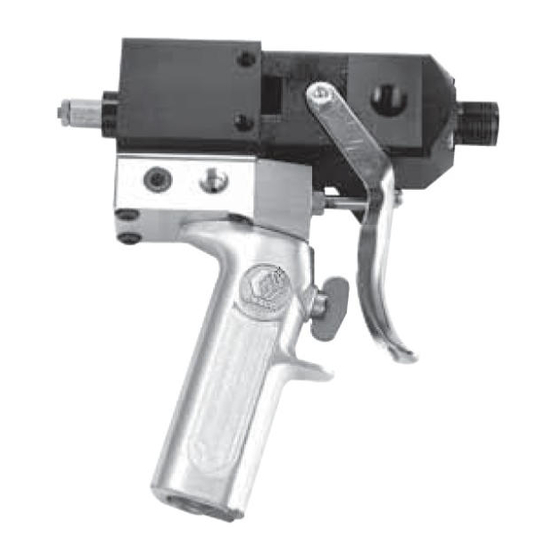
Instructions–Parts List
AIR OPERATED, TWO COMPONENT DISPENSE VALVE
2K Ultra-Litet
For use with disposable mixers to dispense a variety of sealants and adhesives. For
professional use only.
3000 psi (20.7 MPa, 207 bar) Maximum Fluid Working Pressure
120 psi (0.84 MPa, 8.4 bar) Maximum Air Inlet Pressure
Machine Mount Valves
Part No. 570145, Aluminum Wide Ratio
Part No. 570151, For P-Dose 1/2 G mixers
Part No. 965533, Aluminum Wetted
Part No. 965534, Stainless Steel Wetted
Hand Held Valves with Internal Air Trigger
Part No. 570182, Aluminum Wide Ratio
Part No. 965535, Aluminum Wetted
Part No. 249591, Aluminum Wetted,
Bare Valve Without Outlet Manifold
Part No. 965536, Stainless Steel Wetted
Hand Held Valves with Electric Switch
for Remote Operation
Part No. 965537, Aluminum Wetted
Part No. 965538, Stainless Steel Wetted
Important Safety Instructions
Read all warnings and instructions in this manual.
Save these instructions.
See page 2 for Table of Contents.
309000M
Hand Held Valve Shown
EN
Advertisement
Table of Contents

Related Manuals for Graco 2K Ultra-Lite Series


Summary of Contents for Graco 2K Ultra-Lite Series
- Page 1 Instructions–Parts List AIR OPERATED, TWO COMPONENT DISPENSE VALVE 309000M 2K Ultra-Litet For use with disposable mixers to dispense a variety of sealants and adhesives. For professional use only. 3000 psi (20.7 MPa, 207 bar) Maximum Fluid Working Pressure 120 psi (0.84 MPa, 8.4 bar) Maximum Air Inlet Pressure Machine Mount Valves Part No.
-
Page 2: Table Of Contents
......Graco Standard Warranty ..... -
Page 3: Symbols
PLURAL COMPONENT MATERIALS HAZARD Graco Inc. does not manufacture or supply any of the reactive chemical components that are used in this equip- ment and is not responsible for their effects. Because of the vast number of chemicals that could be used and their varying chemical reactions, the buyer and user of this equipment should determine all facts relating to the materials used, including any of the potential hazards involved. - Page 4 Permanently coupled hoses cannot be repaired; replace the entire hose. D Use only Graco approved hoses. Do not remove any spring guard that is used to help protect the hose from rupture caused by kinks or bends near the couplings.
- Page 5 WARNING FIRE AND EXPLOSION HAZARD Improper grounding, poor ventilation, open flames or sparks can cause a hazardous condition and result in a fire or explosion and serious injury. D Ground the equipment and the object being sprayed. Refer to Grounding on page 10. D If there is any static sparking or you feel an electric shock while using this equipment, stop dis- pensing immediately.
-
Page 6: Typical Installation
Typical Installation Shown on a Graco 8900 proportioning system 2K Ultra-Lite valve 1/4 in. npt (f) air to open 1/8 in. npt(f) hand gun air inlet. 8900 Proportioner 1/4 in. npt (f) “A” fluid inlet (3 places) NOTE: The electric switch model has 1/8 “A”... -
Page 7: Features
Features Model Selection The following table provides a summary of the 2K Ultra-Litet dispense valves that are described in this manual. Type Description Wetted parts Aluminum wetted 2K-UL valves are lightweight and inexpensive, but have less chemical compatibility than stainless steel wetted valves. Hand held valves with The internal air trigger controls the air piston that operates the 2K-UL valve. -
Page 8: Electric Switch Valve
Features Electric Switch Valve Figure 2 shows the electric switch valve and provides useful installation information. NOTE: THIS VALVE IS ACTIVATED BY A REMOTE SOLENOID. THE TRIGGER ONLY ACTIVATES THE ELECTRICAL SWITCH IN THE HANDLE. BRING AN “OPEN” AIR SIGNAL TO THE 1/8 in. NPT (F) PORT ON THIS SIDE OF THE VALVE, AND A “CLOSE”... -
Page 9: Ultra-Lite Disposable Mixer Dispenser Valve
Features 2K Ultra-Lite Disposable Mixer Dispense Valve Figure 3 shows the features of the 2K Ultra-Lite valve, which is used for dispensing a wide variety of two compo- nent sealant and adhesives through disposable static mixers. FOUR CONTROL CONFIGURATIONS 1. 1/8 in. NPT (F) PORTED MANIFOLD BLOCK. 2. -
Page 10: Installation
Do not store more than the quantity needed for one shift. D Accessories are available from your Graco repres- D All solvent pails used when flushing: ground ac- entative. If you supply your own accessories, be sure they are adequately sized and pressure-rated cording to local code. -
Page 11: System Setup
System Setup Fluid and Air Connections Selecting Hoses 1/4 npt(f) Fluid Inlets Hoses between your proportioner and the 2K-UL valve should be selected carefully. Many factors effect hose There are three fluid inlets on the A-side and three selection. fluid inlets on the B-side. The fluid inlets are located on the front, side, and back of the valve to permit 1. -
Page 12: Mixer Selection
System Setup Mixer Selection Maximum snuff-back results when both restrictors are used. Some snuff-back is still achieved without the Disposable mixers are available from 3/16 in. I.D. to restrictors because of the pull-back action of the 1/2 in. I.D. in lengths from 12 elements to 36 elements. needles. -
Page 13: Operation
Operation Electric Switch Hand Held Valve WARNING D Be sure the air supply lines are connected correctly COMPONENT RUPTURE HAZARD to the OPEN and CLOSE valve air ports. To reduce the risk of over-pressurization, which can cause component rupture and serious injury, never exceed 3000 psi (21 D To open or close the valve and maintain the open or MPa, 207 bar) fluid pressure, or 120 psi (0.84 MPa,... -
Page 14: Air Switch Hand Held Valve
Operation Air Switch Hand Held Valve Ratio Checking The output mix ratio of your proportioner can be The valve operation is such that there are only two checked by dispensing the two fluids separately out of valve conditions: either fully open or fully closed. the nosepiece into tared cups. -
Page 15: Maintenance
Maintenance Daily Shut-down Preventative Maintenance When you are through using the 2K-UL valve, the outlet to the mixer should be cleaned and protected There is a grease filled secondary seal/bearing area on from drying or crystallization. each valve shaft. Every 10,000 cycles, or twice each month, new grease should be flushed across this area. -
Page 16: Troubleshooting
Troubleshooting Before preforming any troubleshooting procedure, WARNING perform the procedure to relieve the pressure. SKIN INJECTION HAZARD To reduce the risk of serious injury whenever you are instructed to relieve pressure, always follow the Pressure Relief Procedure on page 13. PROBLEM CAUSE SOLUTION... -
Page 17: Service
Service Air Switch Handle (if equipped) WARNING 1. Remove the trigger (59). SKIN INJECTION HAZARD To reduce the risk of serious injury 2. Loosen the set screw above the trigger safety. Pull whenever you are instructed to relieve off the handle (58). pressure, always follow the Pressure Relief Procedure on page 13. -
Page 18: Reassembly
Service Reassembly 3. Holding the bearings (21) in place, push the bear- ing assembly over the shafts (3). Air Cylinder Section 4. Lubricate the main fluid seals (22) and its cavity in 1. Lubricate the shaft o-rings (4) and the bearings (5) the housing (26). - Page 19 Service Air Valve (if equipped) 8. Orient the gasket (30) to the holes on the air cylinder (1). Screw the air valve assembly to the 1. Insert the spring (51) into the housing (63). cylinder with the screws (60) and lock-washers (66).
- Page 20 Service Lube with grease 115982. Line up C-clamp gap with air inlet hole in groove. Orient inlet block and gasket (30) as shown. Plug unused inlet ports. Install grease fittings to one side. Pump grease through valve. Install remaining grease fittings. Shafts (3) fit loose on piston and pin (7) to be self- aligning in seals.
- Page 21 Service Hand Held Valves Air Trigger Version 965535, 965536, or 249591 Electric Switch Version 965537 or 965538 Assembly Notes: The electric switch and cable assembly are not ser- viceable and can only be replaced as an assembly. Torque to 140-150 in/lbs. (15.8-16.9 NSm) Application Note: Apply grease to o-rings.
-
Page 22: Parts
Parts Machine Mount Valves 28, 29 All 965XXX models Outlet Details Models 570145 and 570182 Model 570151 9291A 9290A Fig. 6 309000... -
Page 23: Model 570145, 570151, 570182, 965533, 965535, 965537, 249591
Parts Model 570145, 570151, 570182, 965533, 965535, 965537, 249591 Aluminum Wetted Valves Ref. Part Description Ref. Part Description 626070 HOUSING, air cylinder 32*L 626058 RESTRICTOR, 1/8 ID; 626069 MANIFOLD, air control Used on 965533, 965535, 626068 SHAFT, air cylinder and 965537 only. 156454 O-RING, 010 buna-n 33*L... -
Page 24: Model 965534, 965536, 965538
Parts Model 965534, 965536, 965538 Stainless Wetted Valves Ref. Part No. Description Qty. Ref. Part No. Description Qty. 626070 HOUSING, air cylinder 188378 LABEL, read instruction manual 626069 MANIFOLD, air control 626057 GASKET, air cylinder 626068 SHAFT, air cylinder 626054 NOSEPIECE, sst 156454 O-RING, 010 buna-n... - Page 25 Parts Hand Held Valves Air Trigger Version 965535, 965536, or 249591 Electric Switch Version 965537 or 965538 Note: The electric switch housing, switch, cable, and discon- nect are sold and serviced as a complete assembly. Air Trigger Version Detail 309000...
-
Page 26: Model 570182, 965535, 965536, 249591
Parts Handle Sections of Pneumatic Trigger Valves Model 570182, 965535, 965536, 249591 Ref. Part No. Description Qty. 965533 Valve 106559 O-RING, No. 905 fluoroelastomer 106561 SPRING 106560 O-RING, 007 fluoroelastomer 178651 SPOOL, 4-way 178652 SPACER, u-shape 178653 SPACER, air valve 626055 BUSHING, handle 551204... -
Page 27: Accessories
Accessories Plastic Tube Fittings to Connect Air Signals Tube OD 1/8 NPT (M) Straight 1/8 NPT (M) 90º Swivel 5/32 in. 598140 1/4 in. 104172 597151 Tube OD 1/4 NPT (M) Straight 1/4 NPT (M) 90º Swivel 5/32 in. 598252 598327 1/4 in. -
Page 28: Disposable Mixers
Accessories Disposable Mixers Size Part No. (elem.) Part No. (elem.) Part No. (elem.) Part No. (elem.) 3/16 ID .30 OD 551337 (16) 551338 (24) 551339 (32) 1/4 ID 3/8 OD 512012 (16) 512013 (24) 512014 (32) 3/8 ID 1/2 OD 512016 (24) 512017 (30) 1/2 ID 5/8 OD... -
Page 29: Optional Main Fluid Needle Packings (22)
Accessories Optional Main Fluid Needle Packings (22) Conversion Kits Part No. Description Part No. Description 551193 Reinforced PTFE u–cup with 302 stain- 949631 Pneumatic 4–way valve with housing, less steel spreader handle, and trigger and other parts neces- sary to convert any machine mount valve Application Kits for Spray and Joint Fill to a hand held valve. -
Page 30: Technical Data
Technical Data 2K Ultra–Lite U.S. Metric Maximum Fluid Pressure 3000 psi 207 bar, 20.7 MPa Maximum Cylinder Air Pressure 120 psi 8.4 bar, 0.84 MPa Air inlets (open and close ports) 1/8 npt(f) Fluid Inlet 1/4 npt(f) Fluid Outlet 7/8–14 Bell outlet Fluid Viscosity Range 20 cps to 1 million cps Fluid Section Sealing... -
Page 31: Dimensions
Dimensions 309000... -
Page 32: Graco Standard Warranty
With the exception of any special, extended, or limited warranty published by Graco, Graco will, for a period of twelve months from the date of sale, repair or replace any part of the equipment determined by Graco to be defective.
Need help?
Do you have a question about the 2K Ultra-Lite Series and is the answer not in the manual?
Questions and answers