
Related Manuals for J. D. NEUHAUS PROFI 6 TI


Summary of Contents for J. D. NEUHAUS PROFI 6 TI
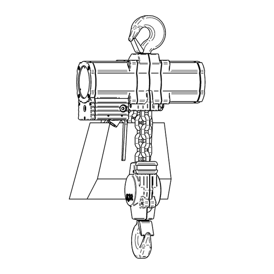
- Page 1 JDN OPERATING AND ASSEMBLY INSTRUCTIONS Hoist PROFI 6 TI Serial No.: P706448 Representation may differ from actual product! ORIGINAL OPERATING AND ASSEMBLY INSTRUCTIONS Doc.-No.: VA057988-10-OM-EN-0821-62-1...
- Page 3 Contact data These operating instructions are a part of the product. Always keep the instructions If you have questions about handling your product on site. that are not answered in these operating instruc- The operating instructions are to be tions, please contact read carefully and in their entirety before handling any product.
-
Page 5: Table Of Contents
ONTENTS Contents 4.2. Storage conditions ..4.2.1. Breaks in operation ..4.2.2. Storage ... . 1. User information 1.1. - Page 6 ONTENTS 8.13.Check lowering limiter ..8.14.Check chain ....8.15.Check chain sprocket ..8.16.Check the chain guide and hook mount .
-
Page 7: User Information
Listings without specified sequence These operating instructions should make it easy Reference to other sections in these operation for you to get to know your product PROFI 6 TI instructions or applicable documents and to take advantage of the intended application possibilities. -
Page 9: Safety Information
2.1. General safety instructions When installing your product PROFI 6 TI in sys- Your product PROFI 6 TI is built according to cur- tems as well as in exceptional cases of use, spe- rent technological standards and the recognised cial regulations may apply. - Page 10 AFETY INFORMATION Adhere to the prescribed maintenance inter- vals. Only use the product for work that is de- scribed as intended. Observe the conditions of use described in these instructions for your product. Page 10 of 62 Doc.-No.: VA057988-10-OM-EN-0821-62-1...
-
Page 11: Product Information
Among others, the following are considered im- 3.1. Proper use proper uses Your product PROFI 6 TI is designed for lifting and Changing load capacities with the load posi- lowering loads in the range of the rated load ca- tion: Your product is not equipped with a load pacity with a vertically arranged chain. -
Page 12: Labelling (Nameplate)
Using special safety precautions that are ap- propriate for the respective situation, your prod- uct PROFI 6 TI can be used for diagonal pull. In the process, a chain box may not be used, as the chain could fall out here or become knotted. -
Page 13: Module Overview
Your product PROFI 6 TI consists of the following In the following, you will receive a description of main modules ( Figure 3): your product PROFI 6 TI and its modules or com- ponents. You will find other technical data in the 1. Gear mechanism appendix. -
Page 14: Explosion Protection Classification
RODUCT INFORMATION 3.5.3. Explosion protection classification 3.5.4. Vane motor Your product PROFI 6 TI is marked according to The vane motor ( Figure 4) consists of a cylin- der liner (1) with two lateral bearing washers and EC directive 2014/34/EU and DIN EN 1127-1 as follows: an inner rotor (2). -
Page 15: Motor Lubrication
3.5.6. Control By pressing the red EMERGENCY STOP button, a separate blocking valve closes and your product PROFI 6 TI instantly comes to a halt and the load CAUTION is held securely in its current position. The control system is now inoperable. -
Page 16: Lifting Limiter
RODUCT INFORMATION 3.5.8. Lifting limiter 3.5.9. Lowering limiter WARNING WARNING Danger from chain fracture Danger from chain fracture If the buffers are damaged, unacceptably high If the buffer is damaged, unacceptably high loads loads may act on the chain when starting the may act on the chain when starting the lowering lifting limiter. -
Page 17: Load Hook
JDN chains may be installed. Your product PROFI 6 TI has 2 falls and the chain size 13 x 36. The chain is manufactured according to DIN EN 818-7. -
Page 18: Chain Container
RODUCT INFORMATION 3.5.12. Chain container 3.5.13. Operation without a chain container WARNING WARNING Danger from chain crash Danger from falling chain There is a danger of chain crash if the chain con- When operating without a chain container, it is tainer capacity is exceeded. -
Page 19: Emissions
Inadmissibly high heating may result. The load capacity of the device is reduced. The Your product PROFI 6 TI is very sturdy and re- response of the control system decreases notice- quires very little maintenance. It is suitable for ap- ably. -
Page 20: Volume
(type no. 11900) with an anti-icing addictive for the corresponding temperatures. Your product PROFI 6 TI must be operated with a sufficiently clean and dry working air. The working air must meet the following quality requirements: Particle size less than 40µm (1,57mils) -
Page 21: Operating Materials
RODUCT INFORMATION 3.9. Operating materials Application area Operating material Motor lubrication JDN high performance grease, item no. 11904 CAUTION (250ml) Engine lubrication for Air lubricator “D”, kine- Danger of skin irritation operation with oiler matic viscosity about Oils and greases may cause skin irritation. (cSt) at 40 C, Wear protective gloves possibly with anti-icing... -
Page 22: Explosion Protection
RODUCT INFORMATION 3.10. Explosion protection impact sparks. Load chain To ensure the required earthing, Earthing Electrostatic ignition hazards can be badly rusted chains may no longer be used in avoided by means of safe earthing. In zones 1 zones 1 and 21 as well as in devices of category and 21, it is required to earth the hoists. - Page 23 RODUCT INFORMATION Emergency lowering Emergency lowering DANGER DANGER Risk of explosion Risk of explosion There is an increased danger of explosion during There is an increased danger of explosion during emergency lowering. Heat is generated in the en- emergency lowering. Heat is generated in the en- gine that cannot be sufficiently dissipated due to gine that cannot be sufficiently dissipated due to the lack of compressed air supply (see “General...
- Page 24 RODUCT INFORMATION Explosion groups and temperature classes of the most important gases and vapours (-selection-) in accordance with (DIN VDE 0165 , Redeker , Nabert , IEC 60079-12 und IEC 60079-20 Explosion pro- Temperature class tection group Ignition temperature >450 C 450-300 C 300-200 C 200-135 C...
- Page 25 RODUCT INFORMATION Decision criteria for selecting the correct JDN products in explosion-hazardous areas Explosion groups for gases and vapours Zone Version Operation (cf. explosion groups and temperature classes for the most important gases and vapours) II A II B (X) except hydrogen sulphide, ethylene oxide (highly flammable) II B II C...
-
Page 26: Ce -Marking
RODUCT INFORMATION 3.11. CE -marking Temperature limits for explosion-hazardous dusts In areas that are potentially explosive Your product PROFI 6 TI is marked with . In the due to combustible dusts, the surface temperature delivered design, your product meets all relevant... -
Page 27: Transport And Storage
4. Motor conservation: If the motor lubrication could lead to malfunctions. is not renewed at the specified intervals, a If you want to transport your product PROFI 6 TI protective coating must be applied to the mo- to another site of application, please observe the tor. -
Page 29: Initial Operation
3m (10 ft), each 1m (1ft) of additional lift increases the weight by 2x 3,8kg (2x 2.6lbs)) of your product PROFI 6 TI during transport. En- sure that the control system is not damaged. This could lead to malfunctions. -
Page 30: Attach The Hoist
The attachment points and supporting struc- ture for your product PROFI 6 TI must be able to securely absorb the forces ( table 1) to be expected. -
Page 31: Connecting The Power Supply
5.6.4) Before tests can be carried out, the chain must be lubricated. The chain of your product PROFI 6 TI must be lubricated in the links in an unloaded state. Clean heavily soiled chains. Place the chain in a suitable container. -
Page 32: Check Control Device
NITIAL OPERATION 5.6.1. Check control device Check with nominal load Alternatively switch your product PROFI 6 TI WARNING loaded with a nominal load to lifting and low- ering Danger from faulty controller If you release a control device, the chain must... -
Page 33: Check Emergency Stop Function
Have the product repaired (replace buffer) 1. Relieve the product PROFI 6 TI. 1. Move the unloaded load hook until just short 2. Move product PROFI 6 TI by using the con- of the upper end position. troller. 2. Stop immediately before reaching the end po- 3. -
Page 34: Check Lowering Limiter
NITIAL OPERATION 5.6.6. Check lowering limiter WARNING Danger from chain fracture If the buffers are damaged, inadmissibly high loads may act on the chain upon actuation of the lowering limiter. The chain may break. Do not use the product Have the product repaired (replace buffer) 1. -
Page 35: Operation
For the safety of persons and property when deal- Always only lift one load, never several loads ing with your product PROFI 6 TI, it is crucial to simultaneously. observe the following points: When lifting and setting down, ensure a stable position of the load to avoid accidents from Never stress the chain to where it bends. -
Page 36: Attaching The Load
PERATION 6.2. Attaching the load Have detached screw connections from repair attached. When lifting loads in non-visible areas, special WARNING safety precautions must be taken. Danger to life from being struck Uncontrolled external force impacts (such as Improper attaching the load can lead to the load from hydraulic cylinder, falling loads) are not crashing down. -
Page 37: Lifting The Load
The hoist can be aligned and the material is Danger from overloading! Ensure that for all appli- protected. cations of your product PROFI 6 TI the load hook Then lift the load. / clevis can be lowered all the way to the ground to avoid a load being driven into the lower limit position without reaching the ground. -
Page 38: Operate The Emergency Stop Device
Only in the case of failure of this stop function, the red EMERGENCY STOP button (1) is to be pressed down firmly. The EMERGENCY STOP button clicks into place. Your product PROFI 6 TI will come to a stop instantly. The push buttons or press buttons are now inoperable. -
Page 39: Decommissioning
ECOMMISSIONING 7. Decommissioning 7.2. Disposal Your product PROFI 6 TI contains a series of ma- 7.1. Disassembly terials that you may have to dispose of or have re- cycled after the end of their useful lives according CAUTION to statutory provisions. -
Page 41: Maintenance
PROFI 6 TI operates safely and operating time. Deviations of the actual mode of reliably over a period of many years. -
Page 42: Model For Determining The Actual Use
AINTENANCE 8.2. Model for determining the actual use The decisive factors for the type of operation are the The FEM 9.511 rule differentiates between four load load spectrums with different cubic averages k. spectrums, which are identified by the definitions The load spectrum indicates to what extent a driving and by the ranges of the cubic averages k. - Page 43 AINTENANCE The following calculation compares the actual operating time with the theoretical operating time in load spec- trum L4 (very heavy). Collective load factor in accor- dance Operating Average Partial Remaining Date Specialist with collective load for the type site daily deployment theoretical use in...
-
Page 44: Maintenance And Inspection Intervals
AINTENANCE 8.3. Maintenance and inspection intervals The specified inspection intervals are valid for use in accordance with the classification. The service life is approx. 10 years if the device is used in accordance with its classification. If your product is used more intensively, the intervals are to be shortened accordingly. All operating hours are translated into full load hours. - Page 45 AINTENANCE Check control valve for sealing efficiency Annually Replace damaged parts if necessary Check the state of the Annually chain container, including mounting Check lifting motor every 200 full load hours 8.19, Page 55 / every 5 years Replace chain at least every 5 years (in corrosive environment) Check chain sprocket...
-
Page 46: Spare Parts
Alcohols are not (cleaning cloth with water). permitted as de-icing agents. If your product PROFI 6 TI is often used at differ- The following operating materials and lubricants ent locations, particularly in dirty and damp envi- are intended for normal environmental influences. -
Page 47: Lubricating The Chain
11904 lubricated. (250ml) Engine lubrication for Air lubricator “D”, kine- The chain of your product PROFI 6 TI must be operation with oiler matic viscosity about lubricated in the links in an unloaded state. (cSt) bei 40 C, Clean heavily soiled chains. -
Page 48: Re-Lubricate The Lifting Motor
AINTENANCE 8.6.3. Re-lubricate the lifting motor the lubricant chambers and secure these us- ing retaining rings. 3. Engine assembly with additional basic lubrica- CAUTION tion of the engine: Danger of injury from pre-tensioned a) Provide the braking surface and rotor springs bearing (needle bush) of the cover with Pre-tensioned springs are released when disas-... - Page 49 AINTENANCE carried out with the device warmed up 4. Check the braking action under nominal load accordingly. (run in the brake by performing several hoist- ing cycles, then assess) prior to initial opera- j) Tighten the nameplate (1) . tion. Check the motor power. In the event of low motor power, regulate the adjusting bolts again.
-
Page 50: Check Control Device
Have the product repaired Have the product repaired Check without load 1. Relieve the product PROFI 6 TI. 2. Briefly actuate and release all control ele- Alternately switch your unloaded product ments of the controls one after the other. The... -
Page 51: Check Emergency Stop Function
1. Move the unloaded load hook until just short 1. Relieve the product PROFI 6 TI. of the upper end position. 2. Move product PROFI 6 TI by using the con- 2. Stop immediately before reaching the end po- troller. -
Page 52: Check Lowering Limiter
WARNING Danger from chain fracture Danger from chain fracture If the chain of your product PROFI 6 TI has one If the buffers are damaged, inadmissibly high of the features listed below, the chain may break loads may act on the chain upon actuation of the upon further use. -
Page 53: Check Chain Sprocket
AINTENANCE 8.15. Check chain sprocket NOTICE If the wear dimensions of a chain sprocket are outside of the limit dimensions indicated below, then the chain sprocket is to be replaced. Figure 16: Four-tooth chain sprocket 32,8 mm 0,25 mm 32,1 mm 0,25 mm Figure 15: Check chain z: Number of teeth of the chain sprocket... -
Page 54: Check The Hook, Shackle And Eyelets
AINTENANCE 8.17. Check the hook, shackle and Checking axial clearance If the axial clear- ance of the installed load hook or clevis exceeds eyelets the maximum clearance specified, the worn parts Check load and support hook If the dimension must be replaced. x, y or h of the load hook (support hook) is outside of the limit value, the hook must be replaced. -
Page 55: Check Silencer
AINTENANCE 8.18. Check silencer 8.19. Check lifting motor CAUTION CAUTION Danger from noise Danger of injury from pre-tensioned By removing the silencer, the noise pressure level springs of the product increases. Pre-tensioned springs are released when disas- Always wear appropriate protection equipment sembling the engine covers. - Page 56 AINTENANCE 2. Checking vane wear: When the vanes (7) are worn, the engine power is reduced. Replace the vanes (7) and starting aids (8) together. Figure 20: Vane Vane dimensions after maximum permissible wear (measured at the thinnest point): 109,5 mm 28,5 mm 4,4 mm 3.
-
Page 57: Replace Chain
Check the motor power. In the event of 6. Switch PROFI 6 TI to Lifting and run the new low motor power, regulate the adjusting bolts chain through the bottom block and drive again. - Page 58 AINTENANCE 8. Mount the components on the idle chain: a) Push the buffer disc with edge (3) (edge encloses the buffer), new buffer (2) and buffer disc without edge onto the chain. b) Insert the 10th chain link into the chain pocket of the clamp sleeve (1) (chain pocket away from the hoist body, facing outward) and secure with bolted connec-...
-
Page 59: Faults, Causes And Remedies
AULTS CAUSES AND REMEDIES 9. Faults, causes and remedies LIFTING NOT POSSIBLE OR ONLY POSSIBLE VERY SLOWLY Possible cause Remedy Insufficient inlet pressure Increase inlet pressure to the required value. Input volume too low Increase input volume to the required value. Hand control is faulty Have hand control repaired. - Page 60 AULTS CAUSES AND REMEDIES EXCESSIVE RUNNING ON DURING BRAKING Possible cause Remedy Brake disc and/ or brake piston worn Replace brake disc and/or brake piston. LOUD NOISE AT THE CHAIN SPROCKET OR GEARBOX Possible cause Remedy Chain dry Lubricate the chain. Check wear. Chain sprocket worn Replace chain sprocket, check chain guide and replace if necessary.
-
Page 61: Technical Data
ECHNICAL DATA A. Technical data metric anglo-american Load capacity 6,3 t 6.9 tn.sh. Number of chain strands Weight with standard lift (3m (10ft)) and control 110 kg 243 lbs Chain dimension 13 x 36 mm Weight of chain 3,8 kg/m 2.6 lbs/ft Air pressure 6 bar... -
Page 62: Dimensions
IMENSIONS B. Dimensions inch 26.5 17.9 19.0 Page 62 of 62 Doc.-No.: VA057988-10-OM-EN-0821-62-1...
Need help?
Do you have a question about the PROFI 6 TI and is the answer not in the manual?
Questions and answers