Table of Contents
Advertisement
Advertisement
Table of Contents

Related Manuals for J. D. NEUHAUS PROFI 3 Ti


Summary of Contents for J. D. NEUHAUS PROFI 3 Ti
- Page 1 J D N O P E R A T I O N M A N U A L A I R H O I S T S...
- Page 2 This manual edition 07/2003, covers the following JDN Air Hoists: Please enter the Fabr. No. of your JDN Air Hoist here. Fabr. No. Fabr. No. Fabr. No. Fabr. No. Before operating any hoist, carefully read the entire manual. For hoists mounted in trolleys, refer also to the JDN Trolleys Operation Manual.
-
Page 3: Table Of Contents
TABLE OF CONTENT S Lifting the load ..... . . 32 S A F E T Y I N S T R U C T I O N S Lowering the load . - Page 4 Please note! Within the Federal Republic of Germany operators of air hoists must comply with UVV Winches, Lifting and pulling Devices (BGV D8) and UVV Load-carrying Devices used with Lifting Equipment (VBG 9a) and, for air hoists installed in trolleys, additionally with UVV Cranes (BGV D6) in the respective currently applicable version.
-
Page 5: Safet Y Ins Tructions
SAFET Y INS TRUCTIONS SAFET Y INS TRUCTIONS O RG A N I S AT I O N A L M E A S U R E S P E R S O N N E L S A F E T Y JDN Air Hoists are designed in accordance with current Personnel who operate, maintain, inspect and perform technological standards and accepted safety practice. -
Page 6: Product Information
PRODUCT INFORMATION PRODUCT INFORMATION T H E O P E R AT I O N M A N UA L WA R N I N G S A N D S Y M B O L S This operation manual is intended to help the operator Safety warnings in this operation manual are classified familiarise himself with JDN Air Hoists and to take full in three categories. -
Page 7: Designation
PRODUCT INFORMATION D E S I G N AT I O N The nameplate mounted on the housing cover identifies the type of JDN Air Hoist and contains all important rating data. If you have any questions concerning operation of JDN Air Hoists, which are not addressed in this operation manual, please contact us at the following address: J.D. -
Page 8: Assembly Overview
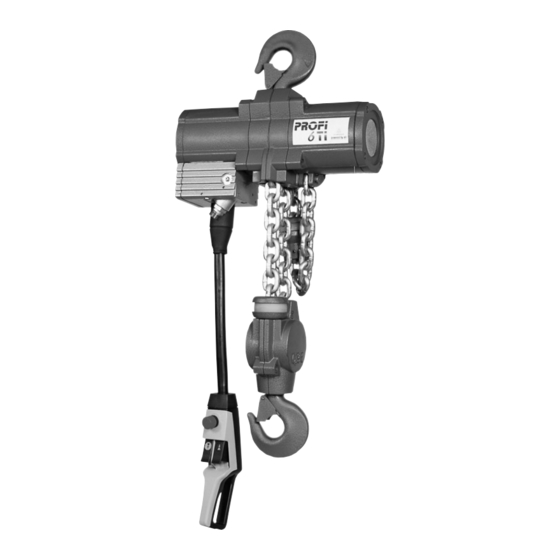
PRODUCT INFORMATION A S S E M B LY O V E R V I E W series air hoists consist of the following assemblies: 1 Gearbox with chain sprocket and overload protection 2 Centre section 3 Motor with integral brake function 4 Controls with main air EMERGENCY STOP 5 Chain 6 Load hook with load sleeve or bottom block and buffer... - Page 9 PRODUCT INFORMATION A D D I T I O N A L M A R K I N G " X " JDN HOIS T S FOR USE IN THE PRESENCE OF TEMPER ATURE CL ASS T6 GASES OR EXTREMELY EXPLOSIVE DUS T S II 3 GD IIA T4 ( X ) : This designation does not permit...
- Page 10 PRODUCT INFORMATION AC E T Y L E N E A N D CO P P E R L OA D C H A I N When operating JDN products in explosion-hazardous In order to prevent mechanical sparking in zones 1 and areas, in which an acetylene-containing atmosphere can 21, but also in zone 2 for gases of explosion group IIC, occur, it must be ensured that copper-plated parts are...
- Page 11 PRODUCT INFORMATION EXPLOSION GROUPS AND TEMPERATURE CLASSES OF THE MOST IMPORTANT GASSES AND VAPOURS (-SELECTION-) (according to DIN VDE 0165 , Redeker , Nabert, Schön , IEC 60079-12 and IEC 60079-20 Ex group Temperature class Ignition temperature > 450°C 450-300°C 300-200°C 200-135°C 135-100°C...
- Page 12 PRODUCT INFORMATION DECISION CRITERIA FOR SELECTING THE CORRECT JDN HOIS T S IN EXPLOSION-HAZARDOUS AREAS Explosion groups of gases and vapours Zone Version* Operation* (cf. Explosion groups and temperature classes of the most important gasses and vapours) II A II B (X) except hydrogen sulphide, ethylene oxide (particularly flammable) II B II C / T4...
- Page 13 PRODUCT INFORMATION The corresponding surface temperatures can be derived T E M P E R AT U R E L I M I T F O R E X P L O S I O N - H A Z A R D O U S D U S T S from the lowest values for glow and ignition tempera- tures of dusts specified in the HVBG/BIA Report 12/97 In areas which are explosion-hazardous due to combu-...
-
Page 14: Intended Use
PRODUCT INFORMATION The brake will drag and is thus subject to a high I N T E N D E D U S E degree of wear. JDN Air Hoists are designed for lifting and DA NG E R ! lowering loads within the specified load-carrying capa- Warning against excessive system pressures cities, with a vertically-arranged chain. -
Page 15: Energy Requirements
PRODUCT INFORMATION The value of the actual pressure p2 at which the hoist E N E RG Y R E Q U I R E M E N T S is operated, depends upon For air pressure, air quantity and connections, see the the weight of the load and table Technical data, page 56. -
Page 16: Principle Of Operation Of Jdn Air Vane Motors
PRODUCT INFORMATION P R I NC I P L E O F O P E R AT I O N 4.1 2 O F J D N A I R VA N E M O T O R S The vane motor consists of a cylinder liner 1 with two side bearing plates and an internal rotor 2. -
Page 17: Operation Without Chain Box
PRODUCT INFORMATION O P E R AT I O N W I T H O U T C H A I N B OX C E R T I F I C AT I O N Each JDN Air Hoist is delivered with a factory certificate. DA N G E R ! If JDN Air Hoists are operated without a chain box, it must be ensured that the idle... -
Page 18: Tr Anspor T And S Tor Age
TR ANSPOR T AND S TOR AGE TR ANSPOR T AND S TOR AGE S A F E T R A N S P O R TAT I O N If you wish to transport your JDN Air Hoist to another site, please observe the following points: Set the housing down carefully;... -
Page 19: Initial Oper Ation
INITIAL OPER ATION INITIAL OPER ATION U N PAC K I NG H O I S T I N S TA L L AT I O N DA NG E R ! C AU T I O N ! JDN Air Hoists must only be installed When unpacking, take account of the weight by qualified persons. -
Page 20: Connecting The Controls
INITIAL OPER ATION CO N N E C T I N G T H E CO N T RO L S CO N N E C T I N G T H E RO P E CO N T RO L S Knot both control ropes at the ends of the control lever. - Page 21 INITIAL OPER ATION Secure the hoses using the one-ear hose clamps and crimping tool. AT T E N T I O N ! To ensure perfect sealing, the "ear" must be fully closed on installation. Pinched one-ear clamp and crimping tool Removal The bellows must be pulled over the other end of the hose bundle including the strain-relief rope (coat...
- Page 22 INITIAL OPER ATION Control valve (on motor) Note: In order to connect the hoses to the control valve, we recommend removal of the hose adapter. Dowel pin Remove the hose adapter (secured via central bolt). Attach the hoses to the corresponding nipples (see designation in illustration) Secure the hoses using the one-ear hose clamps and crimping tool.
-
Page 23: Replacing Controls
INITIAL OPER ATION The control hoses for the drive motors (trolley/crane R E P L AC I N G CO N T RO L S movement) must be extended, outside of the bellows, by means of plug-in connectors and additional control If you wish to exchange air controls E, F or FI, proceed hoses. - Page 24 INITIAL OPER ATION AT T E N T I O N ! CONVERSION FROM AIR CONTROL TO ROPE CONTROL The control hoses must not be subject AT T E N T I O N ! to tensile load; adjust the strain-relief Only air controls without upstream mainstream ropes accordingly.
-
Page 25: Connecting To The Main Air Supply
INITIAL OPER ATION CO N N E C T I N G T O T H E M A I N A I R S U P P LY Check air connection for contamination and clean if necessary. Blow through compressed air hose in order to remove foreign bodies. -
Page 26: Checking Prior To Initial Operation
INITIAL OPER ATION CHECKING PRIOR TO INITIAL OPER ATION Hoists, including the supporting structure, must be inspected by an appropriately trained and qualified person before initial operation and following significant modifications. Hoists which are installed in trolleys must be inspected by a specialist. The inspection covers the proper mounting, equipment level and operational-readiness, in the main, the com- pleteness, suitability and effectiveness of the safety... -
Page 27: Oper Ation
OPER ATION OPER ATION R U L E S F O R S A F E O P E R AT I O N O F H O I S T S As an operator of hoists, you are responsible for your own safety and for that of your colleagues in the working area of the hoist. - Page 28 OPER ATION JDN Air Hoists must not be used for the following appli- Repair damaged hook safety catches. cations, for example: Repair stiff hook bearings. Do not kink or pinch control hoses. Critical areas of nuclear plants. Have loosened bolted connections tightened by the Over acid baths or other plants with Repairs department.
-
Page 29: Controls
OPER ATION Company operating instructions Air control (E-, F-, FI-control) Control valve without upstream main-stream valve In the case of particularly difficult lifting equipment applications, the company must provide comprehensible The control valve consists of: operating instructions in the language of the operator, 1. - Page 30 OPER ATION P U S H B U T T O N F - CO N T RO L With pushbutton F-control, lifting and lowering move- ments can be controlled via two pushbuttons. The direction of movement of the load hook is marked by arrows next to the pushbuttons.
-
Page 31: Emergency Stop Device
OPER ATION Lower: Carefully pull on the red rope with the red E M E RG E NC Y S T O P D E V I C E handle pin. The load is lowered slowly. Pull harder on the rope, in order to increase the Within the EU, these controls are equipped with an lowering speed. -
Page 32: Lifting The Load
OPER ATION In Germany, the Safety Regulations for Load-carrying L OW E R I N G T H E L OA D Devices used with Lifting Equipment must be observed (VBG 9a). In other countries, the relevant national DA NG E R ! regulations are applicable. -
Page 33: Taking Out Of Oper Ation
TAKING OUT OF OPER ATION TAKING OUT OF OPER ATION S H U T T I N G D OW N D I S P O S A L If the hoist is to be take out of operation for a longer JDN Air Hoists contain a range of materials which, on period of time, it must be protected against corrosion. -
Page 34: Maintenance
MAINTENANCE MAINTENANCE M A I N T E N A NC E A N D I N S P E C T I O N A N D R E PA I R S I N S P E C T I O N I N T E R VA L S Series lifting equipment is classified into groups and dimensioned according to the type of operation (Driving JDN Air Hoists are extremely robust and require little... - Page 35 MAINTENANCE Only if the group classification corresponds to the actual type of operation of the lifting equipment, does a safe operating period conform to the theoretical ope- rating time. Deviations of the actual type of operation from that used for calculation extend or shorten the safe operating period.
- Page 36 MAINTENANCE Maintenance measure Interval Comment Check oil level for motor lubrication Daily (Section Filling and adjusting oiler, page 41) (when operating with oiler) Lubricate chain As required (Section Lubricating the chain, page 38) Inspection measure Interval Comment Check control equipment Daily (Section Checking controls, page 38) Check braking function...
-
Page 37: Checking Braking Function
MAINTENANCE C H E C K I N G L I F T I N G C H E C K I N G B R A K I N G F U NC T I O N A N D L OW E R I N G L I M I T E R S Check the function of the brake daily as follows: Move the unloaded load hook until just short of the Switch the unloaded air hoist alternately between... -
Page 38: Lubricating The Chain
MAINTENANCE L U B R I C AT I N G T H E C H A I N C H E C K I N G CO N T RO L S The control elements of the controls must DA N G E R ! always be easily moving. -
Page 39: Service Unit
MAINTENANCE S E R V I C E U N I T AT T E N T I O N ! If a hoist is operated with a service unit, this should not be mounted further than 5 m away from the hoist. The service unit consists either of two elements, filter controller and oiler, or of the filter controller only. - Page 40 MAINTENANCE D R A I N I N G WAT E R After a certain time, liquid collects in the filter regula- tor container, which must be regularly drained. For this purpose, proceed as follows: Check the water level through the sight glass in the filter container.
- Page 41 MAINTENANCE F I L L I N G A N D A D J U S T I N G O I L E R The oiler ensures that the hoist air supply is consistently provided with a precisely-metered quantity of oil. Regular checking of the oiler is very important, as the vane motor may be damaged in the case of lubricant deficiency.
-
Page 42: Replacing Brake Disc And Brake Piston
MAINTENANCE R E P L AC I N G B R A K E D I S C , B R A K E P I S T O N A N D VA N E S / M O T O R I N S TA L L AT I O N / M O T O R L U B R I C AT I O N 12 11 5 13/14... - Page 43 MAINTENANCE Coat the vanes lightly with high-performance grease Rotor and insert into the rotor slots with the starting aids. Cylinder liner Coat the braking surface and the outer diameter V 1 max. = 0,2 mm V 2 max. = 0,2 mm including the brake piston seal lightly with high-per- Brake piston formance grease and push the brake piston with the...
-
Page 44: Removing And Installing Load Sleeve, Bottom Block, Clamp And Buffer
MAINTENANCE REMOVING AND INS TALLING BO TTOM BLOCK REMOVING AND INSTALLING LOAD SLEEVE, AND BUFFERS BOTTOM BLOCK, CLAMP AND BUFFER - D O U B L E FA L L H O I S T S ( 6 T I , 10 T I ) R E M OV I N G A N D I N S TA L L I N G L OA D S L E E V E A N D B U F F E R - S I N G L E FA L L H O I S T ( 3 T I ) - Page 45 MAINTENANCE extent that the end chain link of the idle chain is - T R E B L E FA L L H O I S T ( 16 T I ) not released from the hoist body. In versions with chain box, the idle chain is not attached to the hoist body.
-
Page 46: Checking Chain, Chain Sprocket And Chain Guides
MAINTENANCE Pull the chain from the deflection sprocket of the Remove the clamp from the chain. centre section and from the bottom block. The buf- Detach the buffer 11 and buffer discs 12 + 13 from fers 6, 8, 10 and buffer discs 7, 9, 11 are thereby the chain. -
Page 47: Check Dimensions
Check dimensions of the load hook Type Maximum permis. Minimum permis. dimension of dimension hook opening "a" of height h Profi 3 TI 35.7 36.1 Profi 6 TI 46.0 44.7 Profi 10 TI 50.4 58.9... -
Page 48: Checking Axial Play
MAINTENANCE W E A R D I M E N S I O N S F O R C H A I N S P RO C K E T S C H E C K I N G A X I A L P L AY See check dimensions, page 49. - Page 49 MAINTENANCE When the axial play of the installed hook or load eye exceeds the maximum play specified, the worn parts must be replaced. Bottom block with load hook or load eye Load sleeve with load hook or load eye Page 49...
-
Page 50: Removing And Installing Chain
MAINTENANCE Attach the new chain to the end link of the load R E M OV I N G A N D I N S TA L L I N G C H A I N section of the old chain after aligning the welds and the first chain link by means of an open chain link. -
Page 51: Replacing Chain And Chain Sprocket
MAINTENANCE Fastening of the chains and installation of the load REPL ACING CHAIN AND CHAIN SPROCKET sleeve, clamp, buffer and buffer discs is according to section "Removing and installing load sleeve, bottom Note: If the chain jams in the hoist and can no longer block, clamp and buffer"... -
Page 52: Overload Protection
Do not turn the threaded pins in the process, as the setting will be altered. The PROFI 3 TI, 6 TI, 10 TI and 16 TI hoists are equipped Check the limit value for correct setting. loads exceeding the limit values set from being lifted. -
Page 53: Fault S, C Ause And Remedy
FAULT S, C AUSE AND REMEDY FAULT S, C AUSE AND REMEDY FAU LT TA B L E Fault Possible cause Remedy Lifting not possible Air pressure too low Increase air pressure to the relevant value EMERGENCY STOP switch When the danger has passed, is pressed release the EMERGENCY STOP switch Hand control is faulty... -
Page 54: Accessories
ACCESSORIES ACCESSORIES F I LT E R S I L E NC E R With the use of a filter silencer, oil aerosols can be avoided and noise insulation improved: 99,9 % of oil aerosols during oil lubrication of the motor are absorbed by the filter element. -
Page 55: Booster Unit
ACCESSORIES In all cases, a clamp is attached in the 10th chain link B O O S T E R U N I T of the unloaded chain end so that a length of chain remains in the chain box when the bottom load hook In the case of a control hose length exceeding 10 m, position is reached. -
Page 56: Appendix
APPENDIX APPENDIX T E C H N I C A L DATA Type 3 TI 6 TI 10 TI 16 TI Air pressure Load-carrying capacity Number of chains Motor power Lifting speed at nominal load m/ min Lifting speed without load m/ min Lowering speed at nominal load m/ min... -
Page 57: Dimensions
APPENDIX D I M E N S I O N S Type 3 TI 6 TI 10 TI 16 TI Minimum headroom to centre of hook, without chain box maximum width Page 57... - Page 58 NO TES Page 58...
- Page 59 is a registered trademark of our company. BA 816 GB á Issue: July 2003 á Alterations reserved á With the issue of this edition, all previous versions are null and void á 72003 J.D. Neuhaus GmbH & Co. KG_D-58449 Witten-Heven Phone: +49(0)23 02-2 08-0_Fax: +49(0)23 02-2 08-286 web site: www.jdn.de_e-mail: info@jdn.de...
Need help?
Do you have a question about the PROFI 3 Ti and is the answer not in the manual?
Questions and answers