Table of Contents
Advertisement
Advertisement
Chapters
Table of Contents

Subscribe to Our Youtube Channel
Related Manuals for J. D. NEUHAUS Profi 025Ti


Summary of Contents for J. D. NEUHAUS Profi 025Ti
- Page 1 J D N O P E R A T I O N M A N U A L A I R H O I S T S powered by air!
- Page 2 Please enter the Fabr. No. of your JDN Air Hoist here. This operation manual, edition 4/2005, covers the following JDN Air Hoists: Fabr. No. Fabr. No. Fabr. No. Fabr. No. Before operating any hoist, carefully read the entire manual. For hoists mounted in trolleys, refer also to the JDN Trolleys Operation Manual.
-
Page 3: Table Of Contents
TABLE OF CONTENT S Lowering the load ..... . 36 S A F E T Y I N S T R U C T I O N S Detaching the load . - Page 4 Please note: Within the Federal Republic of Germany operators of air hoists must comply with trade association accident prevention regulations and rules, as well as state occu- pational safety regulations, in particular BGV A1 accident prevention regulations “Principles of Prevention” BGV D8 accident prevention regulations “Winches, Lifting and Pulling Devices”...
-
Page 5: Safet Y Ins Tructions
SAFET Y INS TRUCTIONS SAFET Y INS TRUCTIONS O RG A N I S AT I O N A L M E A S U R E S P E R S O N N E L S A F E T Y JDN hoists are designed in accordance with current Ensure that only properly trained personnel are entrust- technological standards and accepted safety practice. -
Page 6: Product Information
PRODUCT INFORMATION PRODUCT INFORMATION T H E O P E R AT I O N M A N UA L WA R N I N G S A N D S Y M B O L S This operation manual is intended to help the operator Safety warnings in this operation manual are classified familiarise himself with JDN Air Hoists and to take full in three categories:... -
Page 7: Designation
PRODUCT INFORMATION D E S I G N AT I O N The nameplate mounted on the housing cover identifies the type of JDN Air Hoist and contains all important rating data. If you have any questions concerning operation of JDN Air Hoists, which are not addressed in this opera- tion manual, please contact us at the following address: J.D. -
Page 8: Assembly Overview
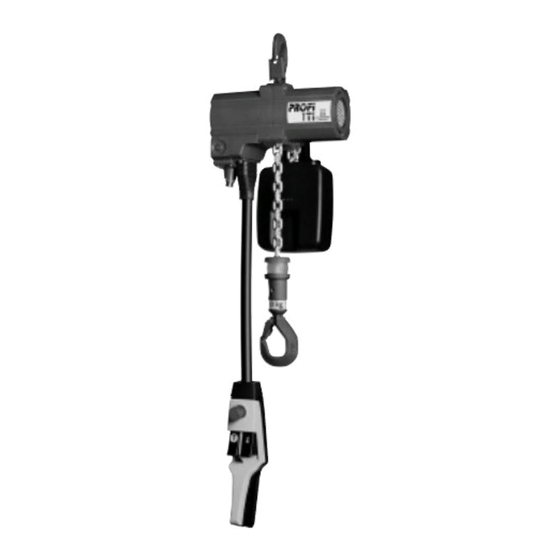
PRODUCT INFORMATION A S S E M B LY O V E R V I E W series air hoists consist of the following assemblies: 1 Gearbox with chain sprocket 2 Centre section 3 Motor with integral brake function 4 Controls with main air EMERGENCY STOP and overload protection 5 Chain 6 Load hook with load sleeve or bottom block... -
Page 9: Explosion Protection
PRODUCT INFORMATION JDN HOIS T S FOR USE IN THE PRESENCE OF TEM- E X P L O S I O N P RO T E C T I O N PER ATURE CL ASS T6 GASES OR EXTREMELY EXPLO- SIVE DUS T S The basis for the following information is an expert Following separate tests, especially with regard to... - Page 10 PRODUCT INFORMATION hoists are available from J. D. NEUHAUS. G E N E R A L N O T E O N D E S I G N AT I O N The maximum permissible surface temperature of 150° C The highest possible respective designations for lifting in accordance with EN 13463-1 for coal dust...
- Page 11 PRODUCT INFORMATION or cast iron) are not used in the working area of the hoists, at potential friction, impact or sliding points. It is thus possible to exclude sparking due to mechanical influences with these material combinations. E A R T H I N G Electrostatic ignition hazards can be prevented by means of safe earthing.
- Page 12 PRODUCT INFORMATION EXPLOSION GROUPS AND TEMPER ATURE CL ASSES OF THE MOS T IMPOR TANT GASES AND VAPOURS (-SELECTION-) (according to DIN VDE 0165 , Redeker , Nabert, Schön , IEC 60079-12 and IEC 60079-20 Ex group Temperature class Ignition temperature >...
- Page 13 PRODUCT INFORMATION DECISION CRITERIA FOR SELECTING THE CORRECT JDN HOIS T S IN EXPLOSION-HAZARDOUS AREAS Explosion groups of gases and vapours Zone Version* Operation* (cf. Explosion groups and temperature classes of the most important gases Manufacturer's Operator's and vapours) responsibility responsibility II A II B (X) except hydrogen sulphide, ethylene oxide...
- Page 14 PRODUCT INFORMATION The corresponding surface temperatures can be derived T E M P E R AT U R E L I M I T S F O R E X P L O S I O N - H A Z A R D O U S D U S T S from the lowest values for glow and ignition tempera- tures of dusts specified in the HVBG/BIA Report 12/97 In areas which are explosion-hazardous due to...
-
Page 15: Intended Use
PRODUCT INFORMATION I N T E N D E D U S E JDN Air Hoists are designed for lifting and lowering loads within the specified load-carrying capacities, with a vertically-arranged chain. JDN Air Hoists from the ranges PROFI 025 TI to 2 TI are also suited to pulling loads horizontally. -
Page 16: Emissions
PRODUCT INFORMATION The brake will drag and is thus subject to a E M I S S I O N S high degree of wear. An impermissibly high degree of warming could take place. The noise emission data can be found in the Technical The controls become noticeably less sensitive. -
Page 17: Energy Requirements
PRODUCT INFORMATION The value of the actual pressure p2 at which the hoist E N E RG Y R E Q U I R E M E N T S is operated depends upon For air pressure, air quantity and connections, the weight of the load and see the Technical data table in the hoist operation the direction of movement of the load. -
Page 18: Principle Of Operation Of
PRODUCT INFORMATION P R I NC I P L E O F O P E R AT I O N O F 4.1 2 J D N A I R VA N E M O T O R S The vane motor consists of a cylinder liner 1 with two side bearing plates and an internal rotor 2. -
Page 19: Operation Without Chain Box
PRODUCT INFORMATION O P E R AT I O N W I T H O U T C H A I N B OX S PA R E PA R T S DA N G E R ! Only use original JDN spare parts. J.D. NEUHAUS If JDN air hoists are operated without a GMBH &... -
Page 20: Safe Transportation
TR ANSPOR T AND S TOR AGE TR ANSPOR T AND S TOR AGE S A F E T R A N S P O R TAT I O N If you wish to transport your JDN Air Hoist to another site, please observe the following points: Carefully dismount trolley (if available). -
Page 21: Setting Up
SETTING UP SETTING UP U N PAC K I NG I N S TA L L I N G T H E H O I S T WA R N I N G ! Mounting the trolley, see trolley operation manual. When unpacking, take account of the weight DA NG E R ! of the hoist. - Page 22 SETTING UP CO N N E C T I N G T H E CO N T RO L S CO N N E C T I N G T H E RO P E CO N T RO L S Knot both control ropes at the ends of the control lever.
- Page 23 SETTING UP Secure the hoses using the one-ear hose clamps and crimping tool. C AU T I O N ! To ensure perfect sealing, the “ear” must be fully closed on installation. Pinched one-ear clamp and crimping tool Removal The bellows must be pulled over the other end of the hose bundle including the strain-relief cable (coat hose bundle with oil for ease of fitting).
- Page 24 SETTING UP CO N N E C T I N G F - CO N T RO L S CO N N E C T I N G F I - CO N T RO L S Pull the bellows over the hose bundle for F-control. Pull the bellows over the hose bundle for FI-control.
-
Page 25: Replacing Controls
SETTING UP • Compressed air R E P L AC I N G CO N T RO L S with hose designation 1 or colour: white • Movement direction “lift” If you wish to exchange air controls E, F or FI, hose designation 2 or colour: green proceed as follows, (see illustrations in section •... -
Page 26: Connecting To The Main Air Supply
SETTING UP Installation of rope controls CO N N E C T I N G T O T H E M A I N A I R S U P P LY Close off the centre air connection using a screw plug G1/8. -
Page 27: Lubricants
SETTING UP L U B R I C A N T S Application Lubricant Motor lubrication - JDN high-performance grease, The following lubricants are intended for normal - from factory Art. no. 11901 (1 kg) - when operating with oiler Art. -
Page 28: Pre-Start Checks
SETTING UP P R E - S TA R T C H E C K S Hoists, including the supporting structure, must be inspected by an appropriately trained and qualified per- son before initial operation and before re-commission- ing after significant modifications. Hoists and lifting gear which are installed in trolleys must be inspected by a specialist. -
Page 29: Oper Ation
OPER ATION OPER ATION R U L E S F O R S A F E O P E R AT I O N O F H O I S T S As an operator of hoists, you are responsible for your own safety and for that of your colleagues in the working area of the hoist. - Page 30 OPER ATION JDN Air Hoists must not be used for the following Ensure that the hook safety catch is closed. applications, for example: Repair damaged hook safety catches. Before lifting loads, ensure that the maximum per- Critical areas of nuclear plants. missible load is not exceeded.
- Page 31 OPER ATION DA N G E R ! For all air hoist applications, ensure that the load hook can be lowered all the way to the ground, in order to prevent a load being moved to the lower limit position, without reaching the ground.
-
Page 32: Controls
OPER ATION E CO N T RO L CO N T RO L S With E-control, lifting and lowering movements can be controlled via two pushbuttons. The direction of move- JDN Air Hoists can be equipped with various control ment of the load hook is marked on the upper side of devices. - Page 33 OPER ATION P U S H B U T T O N F - CO N T RO L With pushbutton F-control, lifting and lowering move- ments can be controlled via two pushbuttons. The direction of movement of the load hook is marked by arrows next to the pushbuttons.
-
Page 34: Emergency Stop Device
OPER ATION Lower: Carefully pull on the red rope with the red E M E RG E NC Y S T O P D E V I C E handle pin. The load is lowered slowly. Within the EU, these controls are equipped with an Pull harder on the rope, in order to increase the EMERGENCY STOP device (optional outside the EU). -
Page 35: Attaching The Load
OPER ATION AT TAC H I N G T H E L OA D DA N G E R ! Only use attaching cables or attaching chains which are suitable for the load. Attaching must not be attempted by winding with the lifting chain around the load. -
Page 36: Lifting The Load
OPER ATION L I F T I N G T H E L OA D D E TAC H I N G T H E L OA D C AU T I O N ! Lower the load hook far enough, so that the JDN Air Hoists must be capable of alignment load can be easily detached. -
Page 37: Taking Out Of Oper Ation
TAKING OUT OF OPER ATION TAKING OUT OF OPER ATION P RO L O N G E D S H U T D OW N D I S P O S A L If the hoist is to be taken out of operation for a longer JDN hoists contain a range of materials which, on period of time it must be protected against corrosion expiry of the service life, must be disposed of or recy-... -
Page 38: Maintenance
MAINTENANCE MAINTENANCE M A I N T E N A NC E A N D I N S P E C T I O N A N D I N S P E C T I O N I N T E R VA L S M A I N T E N A NC E WO R K JDN air hoists are extremely robust and require little Series lifting equipment is classified into groups and... - Page 39 MAINTENANCE Only if the group classification corresponds to the actu- al type of operation of the lifting equipment does a safe operating period conform to the theoretical operating time. Deviations of the actual type of operation from that used for calculation extend or shorten the safe operating period.
-
Page 40: The Actual Operating Time
MAINTENANCE The formula given for the cubic average k does not take I N S T R U C T I O N S O N T H E “ M O D E L the weight of the harness into account. This is permissi- F O R D E T E R M I N I N G T H E AC T UA L ble if the ratio O P E R AT I N G T I M E... - Page 41 MAINTENANCE MODEL FOR DETERMINING THE ACTUAL OPER ATING TIME The following calculation compares the actual operating time with the theoretical operating time in collective load 4 (very heavy). Remaining Average Collective load factor in accor- Partial deploy- Date theoretical daily dance withcollective load for ment use in...
-
Page 42: Lubricating The Chain
MAINTENANCE The specified inspection intervals are valid for use in accordance with the classification (see driving mechanism classifi- cation on the nameplate). The service life is approx. 10 years if the device is used in accordance with its classification. If the hoist is used more intensively the intervals are to be shortened accordingly. The intensity of use must be assessed using the model for determining the actual operating time (see page 40). - Page 43 MAINTENANCE Inspection measure Interval Comment Check sealing efficiency and function Yearly of control valve Check condition of chain box Yearly (Section Chain box, page 62) including mountings Check brake wear and motor wear Every 200 hours, (Section Checking brake linings and vanes, At least every 5 years page 49) In off-shore areas and other similar...
- Page 44 MAINTENANCE L U B R I C AT I N G T H E C H A I N C H E C K I N G B R A K I N G F U NC T I O N The chains of JDN Air Hoist must be lubricated in Check the function of the brake daily as follows: the links, in unloaded condition.
-
Page 45: Checking Lifting And Lowering Limiters
MAINTENANCE C H E C K I N G L I F T I N G A N D C H E C K I N G D I R E C T I O N L OW E R I N G L I M I T E R S O F M OV E M E N T Move the unloaded load hook until just short of the Check that the direction of movement of the load... -
Page 46: Service Unit
MAINTENANCE If the nominal pressure of 5.4 bar (3.6 bar) cannot be S E R V I C E U N I T achieved despite a sufficiently high pressure upstream of the service unit, then the air line cross-section is too AT T E N T I O N ! small. - Page 47 MAINTENANCE D R A I N I N G WAT E R After a certain time, liquid collects in the filter con- troller container, which must be regularly drained. For this purpose, proceed as follows: Check the water level through the sight glass in the filter container.
- Page 48 MAINTENANCE F I L L I N G A N D A D J U S T I N G O I L E R The oiler ensures that the hoist air supply is consistent- ly provided with a precisely-metered quantity of oil. Regular checking of the oiler is very important, as the vane motor may be damaged in the case of lubricant deficiency.
-
Page 49: Motor Installation/Checking Brake Linings And Vanes/Motor Lubrication
MAINTENANCE M O T O R I N S TA L L AT I O N / C H E C K I N G B R A K E L I N I N G S A N D VA N E S / M O T O R L U B R I C AT I O N 10 9 14/15... - Page 50 MAINTENANCE Detach the motor with centre section half on the Rotor motor-side from the hoist. Cylinder liner Remove the bolts 12 and pull out the centre section V 1 max. = 0.2 mm V 2 max. = 0.2 mm half with the brake lining 13. Brake piston Motor installation with additional basic lubrication: Apply high-performance grease lightly to braking...
- Page 51 MAINTENANCE Screw on the nameplate. Push motor with centre section half on the motor side onto the hoist – install load hooks at same time – and tighten centre section bolts. Install the control valve. C AU T I O N ! Tightening torques, see E-list.
-
Page 52: Removing And Installing Load Sleeve
MAINTENANCE REMOVING AND INS TALLING BO TTOM BLOCK REMOVING AND INSTALLING LOAD SLEEVE, AND BUFFERS BOTTOM BLOCK, CLAMP AND BUFFER - D UA L C H A I N H O I S T (2 TI) R E M OV I N G A N D I N S TA L L I N G L OA D S L E E V E A N D B U F F E R - SINGLE CHAIN HOIS T S (025 TI, 05 TI, 1 TI) Removal... - Page 53 MAINTENANCE Note: For assembly, it is helpful to fasten a short R E M OV I N G A N D I N S TA L L I N G C L A M P A N D B U F F E R assembly chain 5 to the end of the chain by means of Removal (see illus.
-
Page 54: Checking Chain, Chain Sprocket And Chain Guides
MAINTENANCE C H E C K I N G C H A I N , C H A I N C H E C K D I M E N S I O N S S P RO C K E T A N D C H A I N G U I D E S H O I S T C H A I N See also Check dimensions, page 54. - Page 55 MAINTENANCE L OA D H O O K W E A R D I M E N S I O N S F O R C H A I N S P RO C K E T S If the measured distance y and the height h of the load hook are outside the wear limits, the hook must be replaced.
-
Page 56: Checking Axial Play
MAINTENANCE C H E C K I N G A X I A L P L AY Maintenance and lubrication Please ensure that load hooks and/or load eye mounts are regularly checked, at least once a year. Especially important: in areas where wear-promoting conditions such as high ambient temperatures or corrosive sub- stances in the atmosphere are present, or where lubri- cants may be washed out, the frequency of mainte-... - Page 57 MAINTENANCE Attach the new chain to the end link of the load sec- R E M OV I N G A N D I N S TA L L I N G C H A I N tion of the old chain after aligning the welds and the first chain link by means of an open chain link.
-
Page 58: Removing And Installing Chain
MAINTENANCE REPL ACING CHAIN AND CHAIN SPROCKET Note: If the chain jams in the hoist and can no longer be run out, the gearbox must be dismantled (see spare parts list for “Gearbox”). For dual chain hoists, when removing the old chain, an assembly chain 1 is brought into position on the deflec- tion sprocket of the bottom block by means of an open chain link (see also Removing and installing load... -
Page 59: Overload Protection
MAINTENANCE OV E R L OA D P RO T E C T I O N The hoists Profi 025 TI to 2 TI are available with an overload protection. Hoists for use within the EU are equipped with this as standard from a carrying capacity of 1 t and above. -
Page 60: Fault S, C Ause And Remedy
FAULT S, C AUSE AND REMEDY FAULT S, C AUSE AND REMEDY FAU LT TA B L E Fault Possible cause Remedy Lifting not possible Overload protection has shut off Lower hook briefly, limit load to permissible load carrying capacity, then lift again Air pressure too low Increase air pressure to the required value EMERGENCY STOP switch is... -
Page 61: Accessories
ACCESSORIES ACCESSORIES F I LT E R S I L E NC E R With the use of a filter silencer, oil aerosols can be avoided and noise insulation improved: 99.9 % of oil aerosols during oil lubrication of the motor are absorbed by the filter element. The noise insulation reduces noise levels by 3 to 4 dB (A) compared with the standard silencer (sinter plate). -
Page 62: Chain Box
ACCESSORIES AT T E N T I O N ! C H A I N B OX Never allow the chain to pile up in the chain box. For various areas of application, a chain box enhances operational safety, i.e. when a chain which is hanging The chain must only enter the container via down could become caught up with the load. -
Page 63: Appendix
APPENDIX APPENDIX T E C H N I C A L DATA J D N P RO F I T I A I R H O I S T S Type 025 TI 05 TI 1 TI 2 TI Load-carrying capacity 0.25 Number of chains Motor rating... -
Page 64: Dimensions
APPENDIX D I M E N S I O N S J D N P RO F I T I A I R H O I S T S Type 025 TI 05 TI 1 TI 2 TI A Minimum headroom* F to centre of hook, without chain box G maximum width *Chain boxes increase the required headroom... - Page 65 NO TES Page 65 powered by air!
- Page 66 NO TES Page 66 powered by air!
- Page 67 NO TES Page 67 powered by air!
- Page 68 is a registered trade mark of our company. BA 817 GB· Issue: April 2005 · Subject to changes · 42005 J.D. Neuhaus GmbH & Co. KG_D-58449 Witten-Heven Phone: +49 2302 208-0_Fax: +49 2302 208-286 Web site: www.jdn.de_E-mail: info@jdn.de powered by air!
- Page 69 J D N O P E R A T I O N A N D A S S E M B L Y I N S T R U C T I O N S A I R H O I S T S Original Operation and Assembly Instructions powered by air!
- Page 70 Please enter the Serial No. of your JDN Air Hoist here. This operation manual edition 12/2009, covers the following JDN Air Hoists: Fabr. No. Fabr. No. It must be read carefully and in its entirety before operating any hoist. For hoists installed in trolleys, please also refer to the operation manual JDN Trolleys.
- Page 71 TABLE OF CONTENT S Detaching the load ..... . 37 S A F E T Y M E A S U R E S Interrupting working .
- Page 72 Please note: Within the Federal Republic of Germany operators of air hoists must comply with trade association accident prevention regulations and rules, as well as state occupational safety regulations, in particular BGV A1 accident prevention regulations “Principles of Prevention” BGV D8 accident prevention regulations “Winches, Lifting and Pulling Devices”...
-
Page 73: Safet Y Measures
SAFET Y MEASURES SAFET Y MEASURES O RG A N I S AT I O N A L M E A S U R E S P E R S O N N E L S A F E T Y JDN Hoists are designed in accordance with current Personnel who operate, maintain, inspect and perform technological standards and accepted safety practice. -
Page 74: Product Information
PRODUCT INFORMATION PRODUCT INFORMATION A B O U T T H I S O P E R AT I O N M A N UA L WA R N I N G S A N D S Y M B O L S This operation manual is intended to help the operator Safety warnings in this operation manual are classified familiarise himself with JDN Air Hoists and to take full... -
Page 75: Identification
PRODUCT INFORMATION I D E N T I F I C AT I O N The nameplate mounted on the housing cover identifies the type of JDN Air Hoist and contains all important rating data. If you have any questions concerning operation of JDN Air Hoists, which are not addressed in this operation Baujahr PROFI... -
Page 76: Assembly Overview
PRODUCT INFORMATION A S S E M B LY OV E R V I E W PROFI TI series air hoists consist of the following assemblies: 1 Gearbox with chain sprocket and overload protection 2 Centre section 3 Motor with integral brake function 4 Controls with main air EMERGENCY STOP 5 Chain 6 Load hook with load sleeve or bottom block... -
Page 77: Explosion Protection
PRODUCT INFORMATION JDN HOISTS FOR USE IN THE PRESENCE OF TEMPERATURE E X P L O S I O N P RO T E C T I O N CLASS T6 GASES OR EXTREMELY EXPLOSIVE DUSTS Following separate tests, especially with regard to The basis for the following information is an expert ambient temperatures and type of operation, use in the statement by the DMT Gas &... - Page 78 PRODUCT INFORMATION and for bronzed or bronze wheels conditions in addition to explosion protection prevailing II 2 GD IIC T6(X), i.e. each including the additional with regard to the general handling of the devices in designation “X” for special conditions. mining applications, special mining hoists are available from J.
- Page 79 PRODUCT INFORMATION points and that material combinations of the above- ACETYLENE AND COPPER named light metals with steel (exception: stainless When operating JDN products in explosion-hazardous steel) are not used in the working area of the hoists, areas, in which an acetylene-containing atmosphere can at potential friction, impact or sliding points.
- Page 80 PRODUCT INFORMATION EXPLOSION GROUPS AND TEMPERATURE CLASSES OF THE MOST IMPORTANT GASES AND VAPOURS (-SELECTION-) (in accordance with DIN VDE 0165 , Redeker , Nabert, Schön , IEC 60079-12 and IEC 60079-20 Explosion Temperature class protection group Ignition temperature > 450° C 450-300°...
- Page 81 PRODUCT INFORMATION DECISION CRITERIA FOR SELECTING THE CORRECT JDN HOIS T S IN EXPLOSION-HAZARDOUS AREAS Explosion groups for gases and vapours Zone Version* Operation* (cf. explosion group and temperature classes for the most important gases and vapours) Manufacturer responsibility Operator responsibility II A II B (X) except hydrogen sulphide, ethylene oxide (highly flammable)
- Page 82 PRODUCT INFORMATION The corresponding surface temperatures can be derived T E M P E R AT U R E L I M I T S F O R E X P L O S I O N - H A Z A R D O U S D U S T S from the lowest values for glow and ignition tempera- tures of dusts specified in the HVBG/BIA Report 12/97 In areas that are potentially explosive due to...
-
Page 83: Intended Use
PRODUCT INFORMATION I N T E N D E D U S E JDN Air Hoists are designed for lifting and lowering loads within the specified load-carrying capacities, with a vertically-arranged chain. JDN Air Hoists from the PROFI 1.5 TI and 3 TI/2 ranges are also suitable for pulling loads horizontally. -
Page 84: Emissions
PRODUCT INFORMATION The brake will drag and is thus subject to a high E M I S S I O N S degree of wear. An impermissibly high degree of warming could take place. The noise emission data can be found in the Technical The controls become noticeably less sensitive. -
Page 85: Energy Requirements
PRODUCT INFORMATION The value of the actual pressure p2 at which the hoist E N E RG Y R E Q U I R E M E N T S is operated, depends upon For air pressure, air quantity and connections, see the the weight of the load and Technical data table in the hoist operation manual the direction of movement of the load. -
Page 86: Principle Of Operation Of Jdn Air Vane Motors
PRODUCT INFORMATION P R I NC I P L E O F O P E R AT I O N O F J D N A I R VA N E M O T O R S The vane motor consists of a cylinder liner 1 with two side bearing plates and an internal rotor 2. -
Page 87: Operation Without Chain Box
PRODUCT INFORMATION O P E R AT I O N W I T H O U T C H A I N B OX S PA R E PA R T S DA N G E R ! Only use original JDN spare parts. J.D. NEUHAUS If JDN Air Hoists are operated without a GMBH &... -
Page 88: Tr Anspor T And S Tor Age
TR ANSPOR T AND S TOR AGE TR ANSPOR T AND S TOR AGE S A F E T R A N S P O R TAT I O N If you wish to transport your JDN Air Hoist to another site, please observe the following points: Carefully dismount trolley (if fitted). -
Page 89: Initial Oper Ation
INITIAL OPER ATION INITIAL OPER ATION U N PAC K I NG I N S TA L L I N G T H E H O I S T C AU T I O N ! Mounting the trolley, see trolley operation manual. When unpacking, take account of the weight DA N G E R ! of the hoist. - Page 90 INITIAL OPER ATION CO N N E C T I N G T H E CO N T RO L S CO N N E C T I N G T H E RO P E CO N T RO L Knot both control ropes at the ends of the control lever.
- Page 91 INITIAL OPER ATION Secure the hoses using the one-ear hose clamps and The bellows must be pulled over the other end of the crimping tool. hose bundle including the strain-relief cable (coat hose bundle with oil for ease of fitting). Pull the AT T E N T I O N ! bellows back far enough to permit further installa- tion.
- Page 92 INITIAL OPER ATION Control valve (on motor) Note: In order to connect the hoses to the control valve, we recommend removal of the hose adapter. Dowel pin Remove the hose adapter (secured via central bolt). Attach the hoses to the corresponding nipples (see designation in illustration) Secure the hoses using the one-ear hose clamps and crimping tool.
-
Page 93: Replacing Controls
INITIAL OPER ATION The control hoses for the drive motors (trolley/crane R E P L AC I N G CO N T RO L S movement) must be extended, outside of the bellows, by means of plug-in connectors and additional control Conversion to another type of control is a significant hoses. - Page 94 INITIAL OPER ATION Direction of movement “lower” AT T E N T I O N ! with hose designation 3 or colour: red The control hoses must not be subject to tensile load; adjust the protective sleeve AT T E N T I O N ! accordingly.
-
Page 95: Connecting To The Main Air Supply
INITIAL OPER ATION CONVERSION FROM AIR CONTROL TO ROPE CONTROL CO N N E C T I N G T O T H E M A I N A I R S U P P LY Air controls can only be installed on rope controls that feature a control shaft. -
Page 96: Lubricants
INITIAL OPER ATION L U B R I C A N T S Application Lubricant Motorlubrication - JDN high-performance grease - at factory Part No. 11901 (250 ml) The following lubricants are intended for normal - for operation with oiler - Air motor oil type “D”, environmental influences. -
Page 97: Inspection Before Initial Operation
INITIAL OPER ATION INSPECTION BEFORE INITIAL OPER ATION Hoists, including the supporting structure, must be inspected by an appropriately trained and qualified person before initial operation and before re- commissioning after significant modifications. Hoists and lifting gear which are installed in trolleys must be inspected by a specialist. -
Page 98: Oper Ation
OPER ATION OPER ATION R U L E S F O R S A F E O P E R AT I O N O F H O I S T S As a hoist operator, you are responsible for your own safety and that of your colleagues in the working area of the hoist. -
Page 99: Controls
OPER ATION JDN Air Hoists must not be used for the following Before lifting loads, ensure that the maximum applications, for example: permitted load is not exceeded. Sling gear must be included in the weight of the load. Critical areas of nuclear plants. When taking up and setting down, ensure stable Over acid baths or other plants with corrosive positioning of the load, to prevent accidents due to... - Page 100 BETRIEB Furthermore, it is essential that all the regulations set DA N G E R ! For all air hoist applications, ensure that the out in sections Intended use, page 15 and Operating load hook can be lowered all the way to the conditions, page 16 are observed.
- Page 101 OPER ATION E CO N T RO L CO N T RO L S With E-control, lifting and lowering movements can be controlled via two pushbuttons. The direction of JDN Air Hoists can be equipped with a variety of movement of the load hook is marked on the upper side control devices.
-
Page 102: Emergency Stop
OPER ATION P U S H B U T T O N F - CO N T RO L With pushbutton F-control, lifting and lowering movements can be controlled via two pushbuttons. The direction of movement of the load hook is marked by arrows next to the pushbuttons. - Page 103 OPER ATION Lowering: Carefully pull on the red rope with the E M E RG E NC Y S T O P D E V I C E yellow handle pin. The load is lowered slowly. Pull harder on the rope, in order to increase the Within the EU, these controls are equipped with an lowering speed.
-
Page 104: Overload Protection
BETRIEB OV E R L OA D P RO T E C T I O N AT TAC H I N G T H E L OA D The overload protection limits the operating pressure of DA N G E R ! the compressed air supplied. -
Page 105: Lifting The Load
OPER ATION L I F T I N G T H E L OA D D E TAC H I N G T H E L OA D AT T E N T I O N ! Lower the load hook far enough, so that the load can JDN Air Hoists must be capable of alignment be easily detached. -
Page 106: Taking Out Of Oper Ation
TAKING OUT OF OPER ATION TAKING OUT OF OPER ATION S H U T T I N G D OW N D I S P O S A L If the hoist is to be taken out of operation for a longer JDN Hoists contain a range of materials which, on period of time it must be protected against corrosion expiry of the service life, must be disposed of or... -
Page 107: Maintenance
MAINTENANCE MAINTENANCE M A I N T E N A NC E A N D I N S P E C T I O N A N D R E PA I R S I N S P E C T I O N I N T E R VA L S Series lifting equipment is classified into groups and dimensioned according to the type of operation (Driving JDN Air Hoists are extremely robust and require little... - Page 108 MAINTENANCE Only if the group classification corresponds to the actual type of operation of the lifting equipment, does a safe operating period conform to the theoretical operating time. Deviations of the actual type of operation from that used for calculation extend or shorten the safe operating period.
-
Page 109: Instructions Concerning The "Model For Determining The Actual Operating Time
MAINTENANCE The formula given for the cubic average k does not INSTRUCTIONS CONCERNING THE “MODEL FOR take the weight of the harness into account. This is DETERMINING THE ACTUAL OPERATING TIME” permissible if the ratio The decisive factors for the type of operation are the load spectrums with different cubic averages k. - Page 110 MAINTENANCE MODEL FOR DETERMINING THE ACTUAL OPER ATING TIME The following calculation compares the actual operating time with the theoretical operating time in load spectrum 4 (Very high). Load spectrum factor in accordance Partial Remaining theoretical Average with load spectrum for the type of deployment use in load spectrum 4 Date...
-
Page 111: Checking Braking Function
MAINTENANCE The specified inspection intervals are valid for use in accordance with the classification (see driving mechanism classi- fication on the nameplate). The service life is approx. 10 years if the device is used in accordance with its classification. If the hoist is used more intensively the intervals are to be shortened accordingly. The intensity of use must be assessed using the model for determining the actual operating time (see page 41). - Page 112 MAINTENANCE Inspection measure Interval Comment Check sealing efficiency and function Annually of control valve Check condition of the chain box Annually (Chain box section, page 63) including mountings Check for brake wear and motor Every 200 hours, (Checking brake linings and vanes section, vane wear at least every 5 years page 50), replace motor vanes every 5 years.
- Page 113 MAINTENANCE L U B R I C AT E C H A I N C H E C K T H E B R A K I N G F U NC T I O N The chain of the JDN Air Hoist must be lubricated Check the function of the brake daily as follows: in the links when not under load.
- Page 114 MAINTENANCE C H E C K I N G L I F T I N G A N D L OW E R I N G L I M I T E R S Move the unloaded load hook until just short of the upper and lower end positions.
-
Page 115: Service Unit
MAINTENANCE Turn the regulator knob until the manometer indi- S E R V I C E U N I T cates the nominal pressure. Clockwise: higher pressure Anti-clockwise: lower pressure AT T E N T I O N ! Lock the regulator knob by pressing it down. If a hoist is operated with a service unit, this should not be mounted further than If the nominal pressure cannot be achieved despite a... - Page 116 MAINTENANCE D R A I N I N G CO N D E N S AT E C L E A N I N G T H E F I LT E R E L E M E N T After a certain time, condensate collects in the filter AT T E N T I O N regulator container, which must be regularly drained.
- Page 117 MAINTENANCE F I L L I N G A N D A D J U S T I N G O I L E R The oiler ensures that the hoist air supply is consistent- ly provided with a precisely-metered quantity of oil. Regular checking of the oiler is very important, as the vane motor may be damaged in the case of lubricant deficiency.
-
Page 118: Motor Installation/Checking Brake Linings And Vanes/Motor Lubrication
MAINTENANCE M O T O R I N S TA L L AT I O N / C H E C K I N G B R A K E L I N I N G S A N D VA N E S / M O T O R L U B R I C AT I O N 13 11 10 9... - Page 119 MAINTENANCE Detach the motor with centre section half on the Rotor Cylinder liner (internal cylinder) motor-side from the hoist. max. = 0.2 mm max. = 0.2 mm Remove the bolts 12 and pull out the centre section Brake piston half with the brake lining 13. Motor installation with additional basic lubrication: Brake disc Apply high-performance grease lightly to braking...
- Page 120 MAINTENANCE Attach the nameplate. Push motor with centre section half on the motor side onto the hoist – install load hooks at same time – and tighten centre section bolts. Install the control valve. AT T E N T I O N ! Tightening torques, see E-list.
-
Page 121: Removing And Installing Load Sleeve, Bottom Block, Clamp And Buffer
MAINTENANCE REMOVING AND INS TALLING BO TTOM BLOCK AND REMOVING AND INSTALLING LOAD SLEEVE, BUFFER - D UA L C H A I N H O I S T (3 TI/2) BOTTOM BLOCK, CLAMP AND BUFFER R E M OV I N G A N D I N S TA L L I N G L OA D S L E E V E A N D B U F F E R –... - Page 122 MAINTENANCE Note: For assembly, it is helpful to fasten a short R E M OV I N G A N D I N S TA L L I N G C L A M P A N D B U F F E R assembly chain 5 to the end of the chain by means of Removal (see illus.
-
Page 123: Checking Chain, Chain Sprocket And Chain Guides
MAINTENANCE C H E C K I N G C H A I N , C H A I N C H E C K D I M E N S I O N S S P RO C K E T A N D C H A I N G U I D E S H O I S T C H A I N See also Check dimensions, page 55. - Page 124 MAINTENANCE L OA D H O O K W E A R D I M E N S I O N S F O R C H A I N S P RO C K E T S If the measured distance y and the height h of the load hook are outside the wear limits, the hook must be replaced.
-
Page 125: Checking Axial Play
MAINTENANCE C H E C K I N G A X I A L P L AY Maintenance and lubrication Please ensure that load hooks and/or load eye mounts are regularly checked, at least once a year. Especially important: in areas where wear-promoting conditions such as high ambient temperatures or corrosive substances in the atmosphere are present, or where lubricants may be washed out, the frequency of... - Page 126 MAINTENANCE Attach the new chain to the end link of the load R E M OV I N G A N D I N S TA L L I N G C H A I N section of the old chain after aligning the welds and the first chain link by means of an open chain link.
- Page 127 MAINTENANCE REPL ACING CHAIN AND CHAIN SPROCKET Note: If the chain jams in the hoist and can no longer be run out, the gearbox must be dismantled (see spare parts list for “Gearbox”). For dual chain hoists, when removing the old chain, an assembly chain 1 is brought into position on the deflection sprocket of the bottom block by means of an open chain link (see also Removing and installing...
- Page 128 The overload protection can also be activated when Then let the load hook run for approx. 10 seconds moving at full unloaded speed against a load to be without a load so that the outlet air cools the clutch lifted, even when it is below the load size set. We down.
- Page 129 FAULT S, C AUSE AND REMEDY FAULT S, C AUSE AND REMEDY FAU LT TA B L E Fault Possible cause Remedy Lifting not possible Overload protection has Lower hook briefly, limit load to permissible caused deactivation load carrying capacity, then lift again. If loads within the load carrying capacity range are not lifted, the overload protection must be adjusted.
- Page 130 ACCESSORIES ACCESSORIES F I LT E R S I L E NC E R With the use of a filter silencer, oil aerosols can be avoided and noise insulation improved: 99.9 % of oil aerosols during oil lubrication of the motor are absorbed by the filter element.
-
Page 131: Removing And Installing Chain
ACCESSORIES AT T E N T I O N ! C H A I N B OX Never allow the chain to pile up in the chain box. For various areas of application, a chain box enhances operational safety, i.e. when a chain which is hanging The chain must only enter the container via down could become caught up with the load. -
Page 132: Appendix
APPENDIX APPENDIX T E C H N I C A L DATA J D N P RO F I T I A I R H O I S T S Type 1.5 TI 3 TI/2 Air pressure 4 to 6 4 to 6 Load-bearing capacity Number of chain sections... - Page 133 APPENDIX D I M E N S I O N S J D N P RO F I T I A I R H O I S T S Type 1.5 TI 3 TI/2 A minimum headroom* F to centre of hook, without chain box G maximum width *Chain boxes increase the required headroom Page 65...
- Page 134 APPENDIX C I RC U I T D I AG R A M RO P E CO N T RO L , W I T H O U T M A I N A I R E M E RG E NC Y S T O P VA LV E lifting motor motor brake...
- Page 135 APPENDIX C I RC U I T D I AG R A M lifting motor E - CO N T RO L , D UA L - F U NC T I O N , W I T H O U T E M E RG E NC Y S T O P D E V I C E W I T H O U T M A I N A I R E M E RG E NC Y S T O P VA LV E motor brake...
- Page 136 APPENDIX C I RC U I T D I AG R A M E - CO N T RO L , D UA L - F U NC T I O N , lifting motor W I T H E M E RG E NC Y S T O P D E V I C E W I T H M A I N A I R E M E RG E NC Y S T O P VA LV E motor brake...
- Page 137 APPENDIX C I RC U I T D I AG R A M E - CO N T RO L , 4 - F U NC T I O N , W I T H O U T E M E RG E NC Y S T O P D E V I C E W I T H O U T M A I N A I R E M E RG E NC Y S T O P VA LV E ( N O T F O R E E A ) lifting motor...
- Page 138 APPENDIX C I RC U I T D I AG R A M E - CO N T RO L , 4 - F U NC T I O N , W I T H E M E RG E NC Y S T O P D E V I C E W I T H E X T E R N A L M A I N A I R E M E RG E NC Y S T O P VA LV E lifting motor...
- Page 139 APPENDIX C I RC U I T D I AG R A M F I - CO N T RO L , D UA L - F U NC T I O N , lifting motor W I T H E M E RG E NC Y S T O P D E V I C E W I T H M A I N A I R E M E RG E NC Y S T O P VA LV E motor brake...
- Page 140 APPENDIX C I RC U I T D I AG R A M F - CO N T RO L , 5 - F U NC T I O N ( D E V I C E W I T H T RO L L E Y ) , W I T H E M E RG E NC Y S T O P D E V I C E , W I T H E X T E R N A L M A I N A I R lifting motor...
- Page 141 APPENDIX C I RC U I T D I AG R A M F - CO N T RO L , 7 - F U NC T I O N ( D E V I C E W I T H T RO L L E Y C R A N E ) , W I T H E M E RG E NC Y S T O P D E V I C E W I T H E X T E R N A L M A I N A I R E M E RG E NC Y S T O P VA LV E lifting motor...
- Page 142 is a registered trade mark of our company. BA 820 GB · Subject to changes · 122009 J.D. Neuhaus GmbH & Co. KG / D-58449 Witten-Heven Phone: +49 2302 208-0 / Fax: +49 2302 208-286 web site: www.jdn.de / e-mail: info@jdn.de powered by air!
- Page 143 J D N O P E R A T I O N A N D A S S E M B L Y I N S T R U C T I O N S A I R H O I S T S M O N O R A I L H O I S T S E H 1 0 , E H 1 6 , E H 2 0 Original Operation and...
- Page 144 Please enter the Fabr. No. of your JDN Air Hoist here. This operation manual edition 12/2009, covers the following JDN Air Hoists: Fabr. No. Fabr. No. Fabr. No. Fabr. No. Fabr. No. and the following JDN Monorail Hoists (EH), only in conjunction with the operation manual JDN Trolleys: EH 10 EH 16...
- Page 145 TABLE OF CONTENTS Lowering the load ..... . . 35 SA F E T Y M E A S U R E S Detaching the load .
- Page 146 Please note: Within the Federal Republic of Germany operators of air hoists must comply with trade association accident prevention regulations and rules, as well as state occupational safety regulations, in particular BGV A1 accident prevention regulations ”Principles of Prevention” BGV D8 accident prevention regulations ”Winches, Lifting and Pulling Devices”...
-
Page 147: Organisational Measures
SAFETY INSTRUCTIONS SAFETY INSTRUCTIONS O R GA N I SAT I O N AL M E A S U R E S P E R S O N N E L SA F E T Y JDN Hoists are designed in accordance with current Personnel who operate, maintain, inspect and perform technological standards and accepted safety practice. -
Page 148: Product Information
PRODUCT INFORMATION PRODUCT INFORMATION T H E OP E R AT I O N M A N UAL WA R N I N G S A N D SY M B O L S This operation manual is intended to help the operator Safety warnings in this operation manual are classified familiarise himself with JDN Air Hoists and to take full in three categories. -
Page 149: Labelling
PRODUCT INFORMATION L A B E L L I N G The nameplate mounted on the housing cover identifies the type of JDN Air Hoist and contains all important rating data. If you have any questions concerning operation of JDN powered by air ! Air Hoists, which are not addressed in this operation manual, please contact us at the following address:... -
Page 150: Assembly Overview
PRODUCT INFORMATION A S S E M B LY OVE R V I E W PROFI TI air hoists and monorail hoists consist of the following assemblies: 1 Gearbox with chain sprocket and overload protection 2 Centre section 3 Motor with integral brake function 4 Controls with main air EMERGENCY STOP 5 Chain 6 Load hook with load sleeve or bottom block and buffer... -
Page 151: Explosion Protection
PRODUCT INFORMATION JDN HOISTS FOR USE IN THE PRESENCE OF E X P L O S I O N P R OT E C T I O N TEMPERATURE CLASS T6 GASES OR EXTREMELY EXPLOSIVE DUSTS The basis for the following information is an expert Following separate tests, especially with regard to statement by the DMT Gas &... - Page 152 PRODUCT INFORMATION J.D. NEUHAUS. The maximum permissible temperature G E N E R AL N OT E O N D E S I G N AT I O N of 150° C in accordance with EN 13463-1 for coal dust The highest possible respective designations for lifting atmospheres is not reached.
- Page 153 PRODUCT INFORMATION friction, impact or sliding points. It is thus possible to exclude sparking due to mechanical influences with these material combinations. The external housing of the service units is made of aluminium. Therefore the installation position is to be selected so as to ensure that there is no risk from impact sparks.
- Page 154 PRODUCT INFORMATION EXPLOSION GROUPS AND TEMPERATURE CLASSES OF THE MOST IMPORTANT GASES AND VAPOURS (-SELECTION-) (in accordance with DIN VDE 0165 , Redeker , Nabert, Schön , IEC 60079-12 and IEC 60079-20 Ex group Temperature class Ignition temperature > 450° C 450-300°...
- Page 155 PRODUCT INFORMATION DECISION CRITERIA FOR SELECTING THE CORRECT JDN HOISTS IN EXPLOSION-HAZARDOUS AREAS Explosion groups of gases and vapours Zone Version* Operation* Manufacturer’s Operator’s (See Explosion groups and temperature classes of the most important gases and vapours) responsibility responsibility II A II B (X) except hydrogen sulphide, ethylene oxide (particularly flammable) II B...
- Page 156 PRODUCT INFORMATION The corresponding surface temperatures can be derived T E M P E R AT U R E L I M I T S F O R E X P L O S I O N - H A Z A R D O U S D U S T S from the lowest values for glow and ignition temperatures of dusts specified in the HVBG/BIA Report In areas which are explosion-hazardous due to com-...
-
Page 157: Intended Use
PRODUCT INFORMATION I N T E N D E D U S E OP E R AT I N G C O N D I T I O N S JDN Air Hoists are designed for lifting and lowering JDN Air Hoists are extremely robust and require little loads within the specified load-carrying capacities, with maintenance. - Page 158 PRODUCT INFORMATION In order to provide adequate compressed air quality, operation with a service unit is recommended. Usually, an oiler is not required in the service unit, as the motor is provided with internal permanent lubrication. Pressure dew point at least 10° C below the lowest expected ambient temperature.
-
Page 159: Energy Requirements
PRODUCT INFORMATION The value of the actual pressure p2 at which the hoist E N E R G Y R E Q U I R E M E N T S is operated, depends upon For air pressure, air quantity and connections, see the the weight of the load and Technical data table in the hoist operation manual the direction of movement of the load. -
Page 160: Principle Of Operation Of
PRODUCT INFORMATION P R I N C I P L E O F OP E R AT I O N O F J D N A I R VA N E M OTO R S The vane motor consists of a cylinder liner 1 with two side bearing plates and an internal rotor 2. -
Page 161: Operation Without Chain Box
PRODUCT INFORMATION OP E R AT I O N W I T H O U T C H A I N B OX S PA R E PA R T S DA N G E R ! Only use original JDN spare parts. J.D. NEUHAUS If JDN Air Hoists are operated without a GMBH &... -
Page 162: Transport And Storage
TRANSPORT AND STORAGE TRANSPORT AND STORAGE SA F E T R A N S P O R TAT I O N If you wish to transport your JDN Air Hoist to another site, please observe the following points: Carefully dismount trolley (if available). Set the entire hoist down carefully;... -
Page 163: Initial Operation
INITIAL OPERATION INITIAL OPERATION DA N G E R ! U N PAC K I N G The supporting structure of the air hoist must form a rigid mounting. Vibration damages the C AU T I O N ! chain and can lead to chain fracture. When unpacking, take account of the weight Furthermore, external vibration must on no of the hoist. - Page 164 INITIAL OPERATION C O N N E C T I N G T H E C O N T R O L S C O N N E C T I N G T H E R OP E C O N T R O L S Knot both control ropes at the ends of the control lever.
- Page 165 INITIAL OPERATION Secure the hoses using the one-ear hose clamps and Installation example crimping tool. Position the clamp on the hose with nipple. Crimp the clamp ear until fully closed. AT T E N T I O N ! To ensure perfect sealing, the ”ear” must be fully closed on installation.
- Page 166 INITIAL OPERATION Control valve (on motor) Note: In order to connect the hoses to the control valve, we recommend removal of the hose adapter. Dowel pin Remove the hose adapter (secured via central bolt). Attach the hoses to the corresponding nipples (see designation in illustration).
-
Page 167: Replacing Controls
INITIAL OPERATION The control hoses for the drive motors (trolley/crane R E P L AC I N G C O N T R O L S movement) must be extended, outside of the bellows, by means of plug-in connectors and additional control Conversion to another type of control is a significant hoses. - Page 168 INITIAL OPERATION AT T E N T I O N ! CONVERSION FROM AIR CONTROL TO ROPE CONTROL The control hoses must not be subject to AT T E N T I O N ! tensile load; adjust the strain-relief cables Only air controls without upstream main- accordingly.
-
Page 169: Connecting To The Main Air Supply
INITIAL OPERATION C O N N E C T I N G TO T H E M A I N A I R S U P P LY Check air connection for contamination and clean if necessary. Blow through compressed air hose in order to remove foreign bodies. -
Page 170: Checking Prior To Initial Operation
INITIAL OPERATION C H E C K I N G P R I O R TO I N I T I AL OP E R AT I O N Application Lubricant Motor lubrication - JDN high-performance Hoists, including the supporting structure, must be grease, - from factory Art. -
Page 171: Operation
OPERATION OPERATION R U L E S F O R SA F E OP E R AT I O N O F H O I S T S As an operator of hoists, you are responsible for your own safety and for that of your colleagues in the working area of the hoist. -
Page 172: Controls
OPERATION JDN Air Hoists must not be used for the following During lifting and lowering, prevent accidents by applications, for example: ensuring that the load remains stable and does not tilt or fall. Critical areas of nuclear plants. Never drive against jammed loads. Over acid baths or other facilities containing corrosive Only use original JDN chain boxes. - Page 173 OPERATION DA N G E R ! For all air hoist applications, ensure that the load hook can be lowered all the way to the ground, in order to prevent a load being moved to the lower limit position, without reaching the ground.
- Page 174 OPERATION Air control (E-, F-, FI-control) C O N T R O L S Control valve without upstream main-stream valve JDN Air Hoists can be equipped with a variety The control valve consists of: of control devices. They are all suitable for use in 1.
- Page 175 OPERATION P U S H B U T TO N F - C O N T R O L With pushbutton F-control, lifting and lowering movements can be controlled via two pushbuttons. The direction of movement of the load hook is marked by arrows next to the pushbuttons.
-
Page 176: Emergency Stop Device
OPERATION Lower: Carefully pull on the red rope with the yellow E M E R G E N C Y S TOP D E V I C E handle pin. The load is lowered slowly. Pull harder on the rope, in order to increase the Within the EU, these controls are equipped with an lowering speed. -
Page 177: Lifting The Load
OPERATION In Germany, the trade association regulations ”Operation First, lift the load hook, in order to pull the slack of load carrying devices used with lifting equipment” chain tight. With the chain tight, briefly interrupt (BGR 258) must be adhered to. In other countries, the the lifting procedure. -
Page 178: Taking Out Of Operation
TAKING OUT OF OPERATION TAKING OUT OF OPERATION S H U T T I N G D OW N D I S P O SAL If the hoist is to be taken out of operation for a longer JDN Hoists contain a range of materials which, on period of time it must be protected against corrosion expiry of the service life, must be disposed of or and dirt. -
Page 179: Maintenance
MAINTENANCE MAINTENANCE M A I N T E N A N C E A N D I N S P E C T I O N A N D R E PA I R S I N S P E C T I O N I N T E R VAL S Series lifting equipment is classified into groups and dimensioned according to the type of operation (Driving JDN Air Hoists are extremely robust and require little... - Page 180 MAINTENANCE Only if the group classification corresponds to the actual type of operation of the lifting equipment, does a safe operating period conform to the theoretical operating time. Deviations of the actual type of operation from that used for calculation extend or shorten the safe operating period.
-
Page 181: Instructions Concerning The "Model For Determining The Actual Operating Time
MAINTENANCE The formula given for the cubic average k does not I N S T R U C T I O N S C O N C E R N I N G T H E take the weight of the harness into account. This is ”... - Page 182 MAINTENANCE MODEL FOR DETERMINING THE ACTUAL OPERATING TIME The following calculation compares the actual operating time with the theoretical operating time in collective load 4 (very heavy). Remaining Average Collective load factor in accor- Partial Date theoretical daily dance withcollective load for deployment use in Delivery...
-
Page 183: Lubricate The Chain
MAINTENANCE The specified inspection intervals are valid for use in accordance with the classification (see driving mechanism classi- fication on the nameplate). The service life is approx. 10 years if the device is used in accordance with its classification. If the hoist is used more intensively the intervals are to be shortened accordingly. The intensity of use must be assessed using the model for determining the actual operating time (see page 39). - Page 184 MAINTENANCE Inspection measure Interval Comment Check sealing efficiency and function Annually of control valve Check condition of the chain box Annually (Chain box section, page 63) including mountings Check for brake wear and motor Every 200 hours, at least (Replacing brake disc, brake piston and vanes vane wear every 5 years section, page 48), replace motor vanes every 5 years...
-
Page 185: Checking Lifting And Lowering Limiters
MAINTENANCE For physical reasons, the braking distance cannot have the L U B R I C AT E T H E C H A I N value zero. However, for the purpose of this functional check, running on of the chain must not be The chains of JDN Air Hoist must be lubricated in the perceptible.When checking the braking function under links, in unloaded condition. -
Page 186: Checking Controls And Emergency Stop Function
MAINTENANCE With each check, the working order of the valve must C H E C K I N G C O N T R O L S A N D be examined as follows: E M E R G E N C Y S TOP F U N C T I O N Shut off the compressed air supply and unload the line. -
Page 187: Service Unit
MAINTENANCE Lock the regulator knob by pressing it down. S E R V I C E U N I T Values for 4-bar hoists in brackets AT T E N T I O N ! If the nominal pressure of 5.4 bar (3.6 bar) cannot be If a hoist is operated with a service unit, this achieved despite a sufficiently high pressure upstream should not be mounted further than 5 m... - Page 188 MAINTENANCE D R A I N I N G C O N D E N SAT E C L E A N I N G T H E F I LT E R E L E M E N T After a certain time, condensate collects in the filter AT T E N T I O N regulator container, which must be regularly drained.
- Page 189 MAINTENANCE Oil drop rate (lifting without load): F I L L I N G A N D A D J U S T I N G O I L E R 10 drops per minute. The oiler ensures that the hoist air supply is consistently provided with a precisely-metered quantity AT T E N T I O N ! of oil.
-
Page 190: Replacing Brake Disc, Brake Piston And Vanes /Motor Installation/Motor Lubrication
MAINTENANCE R E P L AC I N G B R A K E D I S C , B R A K E P I S TO N A N D VA N E S / M OTO R I N S TAL L AT I O N / M OTO R L U B R I C AT I O N 1211 13/14... - Page 191 MAINTENANCE performance grease and push the brake piston with Rotor Cylinder liner the braking surface first into the internal cylinder; max. = 0,2 mm max. = 0,2 mm note the position of the eccentric bore. Brake piston Insert the brake springs into the bores of the brake piston.
-
Page 192: Removing And Installing Load Sleeve, Bottom Block, Clamp And Buffer
MAINTENANCE L OA D S L E E VE I N S P E C I AL D E S I G N REMOVING AND INSTALLING LOAD SLEEVE, W I T H C L A M P I N G P I E C E BOTTOM BLOCK, CLAMP AND BUFFER R E M OV I N G A N D I N S TAL L I N G L OA D S L E E VE A N D B U F F E R... - Page 193 MAINTENANCE REMOVING AND INSTALLING BOTTOM BLOCK Remove the chain link 1 of the bottom block from AND BUFFERS the chain mount on the hoist body by driving out the roll pin 2 and pull out the chain link pin 3 (the end - D O U B L E C H A I N H O I S T S (6 TI, 10 TI, EH 10) chain link 4 of the idle chain is released simulta- neously) or only pull out the chain link pin to the...
- Page 194 MAINTENANCE Note: For assembly, it is helpful to work with two short - T R E B L E C H A I N H O I S T S ( 1 6 T I , E H 1 6 ) assembly chains 4 which are fastened by means of an open chain link 5 to the hoist chain being pulled out during removal of the chain and are pulled successively...
- Page 195 MAINTENANCE Note: For subsequent assembly, it is helpful to work Q UA D R U P L E C H A I N H O I S T S ( 2 0 T I , E H 2 0 ) with three short assembly chains 5 which are fastened by means of an open chain link 6 to the hoist chain being pulled out during removal of the chain and are...
-
Page 196: Checking Chain, Chain Sprocket And Chain Guides
MAINTENANCE Align the chain and fasten the end chain link to the Drive in a new roll pin to secure the chain link in hoist body by means of the end chain link pin. the clamp. (Position of the weld must align with that of the Attach the chain box. -
Page 197: Check Dimension
MAINTENANCE L OA D H O O K C H E C K D I M E N S I O N If die hook opening a and the height h of the load hook are outside the wear limits, the hook must be H O I S T C H A I N replaced. -
Page 198: Checking Axial Play
MAINTENANCE W E A R D I M E N S I O N S F O R C H A I N S P R O C K E T S C H E C K I N G A X I AL P L AY Maintenance and lubrication Please ensure that load hooks and/or load eye mounts are regularly checked, at least once a year. -
Page 199: Removing And Installing Chain
MAINTENANCE C H E C K D I M E N S I O N S F O R T H E A X I AL P L AY R E M OV I N G A N D I N S TAL L I N G C H A I N Bottom block type Axial play ”x”... -
Page 200: Replacing Chain And Chain Sprocket
MAINTENANCE The welds on the upright chain links must face out- R E P L AC I N G C H A I N A N D wards when running over the chain sprockets. For this C H A I N S P R O C K E T reason, the welds of the chain links which lie flat in the drive sprocket must face towards the gearbox in Note: If the chain jams in the hoist and can no longer... -
Page 201: Overload Protection
MAINTENANCE Fastening of the chains and installation of the load AT T E N T I O N ! sleeve, clamp, buffer and buffer discs is carried out in The safety clutch must only be engaged for accordance with the Removing and installing load a short time in order to prevent unnecessary sleeve, bottom block, clamp and buffer section and wear and overheating of the drive. - Page 202 MAINTENANCE R E S E T T I N G T H E L I M I T VAL U E Loosen the lock nuts. Screw out the threaded pins - anti-clockwise - until the disc springs (4) are completely free of pre-tension. Then loosely screw in the threaded pins by hand –...
-
Page 203: Faults, Cause And Remedy
FAULTS, CAUSE AND REMEDY FAULTS, CAUSE AND REMEDY FAU LT TA B L E Fault Possible cause Remedy Lifting not possible Air pressure too low Increase air pressure to the required value EMERGENCY STOP button is Release the EMERGENCY-OFF switch pressed if the danger has been rectified Hand control is faulty... -
Page 204: Accessories
ACCESSORIES ACCESSORIES F I LT E R S I L E N C E R With the use of a filter silencer, oil aerosols can be avoided and noise insulation improved: 99.9 % of oil aerosols during oil lubrication of the motor are absorbed by the filter element. -
Page 205: Chain Box
ACCESSORIES AT T E N T I O N ! C H A I N B OX Never allow the chain to pile up in the chain box. For various areas of application, a chain box enhances operational safety, i.e. when a chain which is hanging The chain must only enter the container via down could become caught up with the load. -
Page 206: Appendix
APPENDIX APPENDIX T E C H N I C AL DATA J D N P R O F I T I A I R H O I S T S Type 3 TI 6 TI 10 TI 16 TI 20 TI Air pressure Load-carrying capacity Number of chains... -
Page 207: Dimensions
APPENDIX D I M E N S I O N S J D N P R O F I T I A I R H O I S T S Type 3 TI 6 TI 10 TI 16 TI 20 TI * Minimum headroom 1040 to centre of hook, without chain box... - Page 208 APPENDIX T E C H N I C AL DATA J D N M O N O R A I L H O I S T S Type EH 10 EH 16 EH 20 Air pressure Load-carrying capacity Number of chains Motor power, running gear Motor power, lifting gear Lifting speed at nominal load...
- Page 209 APPENDIX D I M E N S I O N S b + B Type EH 10 EH 16 EH 20 Measurements in mm * Chain boxes increase the required headroom Page 67 powered by air!
-
Page 210: Air Flow Sheets
APPENDIX A I R F L OW S H E E T S R OP E C O N T R O L , W I T H O U T M A I N A I R E M E R G E N C Y- S TOP VALVE Hubmotor lifting motor senken... - Page 211 APPENDIX E - C O N T R O L , 2 - F O L D , W I T H E M E R G E N C Y S TOP F U N C T I O N W I T H M A I N A I R E M E R G E N C Y- S TOP VALVE Hubmotor lifting motor...
- Page 212 APPENDIX E - C O N T R O L , 4 - F O L D , W I T H O U T E M E R G E N C Y S TOP F U N C T I O N W I T H O U T M A I N A I R E M E R G E N C Y- S TOP VALVE ( N OT F O R E W R ) Fahrmotor...
- Page 213 APPENDIX E - C O N T R O L , 4 - F O L D , W I T H E M E R G E N C Y S TOP F U N C T I O N W I T H E X T E R N AL M A I N A I R E M E R G E N C Y- S TOP VALVE Hubmotor Fahrmotor...
- Page 214 APPENDIX F I - C O N T R O L , 2 - F O L D , W I T H E M E R G E N C Y S TOP F U N C T I O N W I T H M A I N A I R E M E R G E N C Y- S TOP VALVE Hubmotor lifting motor...
- Page 215 APPENDIX F - C O N T R O L , 5 - F O L D , W I T H E M E R G E N C Y S TOP F U N C T I O N W I T H M A I N A I R E M E R G E N C Y- S TOP VALVE Hubmotor Fahrmotor...
- Page 216 APPENDIX F - C O N T R O L , 7 - F O L D , W I T H E M E R G E N C Y S TOP F U N C T I O N W I T H M A I N A I R E M E R G E N C Y- S TOP VALVE driving motor Fahrmotor...
- Page 218 is a registered trademark of our company. BA 816 GB · Edition: December 2009 · Subject to changes · 122009 J.D. NEUHAUS GMBH & CO. KG _ D-58449 WITTEN-HEVEN PHONE +49 2302 208-0 _ FAX +49 2302 208-286 info@jdn.de _ www.jdn.de powered by air!
Need help?
Do you have a question about the Profi 025Ti and is the answer not in the manual?
Questions and answers