Table of Contents
Advertisement
Quick Links
Advertisement
Table of Contents

Related Manuals for Supermicro SuperServer 5029AP-TN2


Summary of Contents for Supermicro SuperServer 5029AP-TN2
- Page 1 SuperServer ® 5029AP-TN2 USER’S MANUAL Revision 1.0...
- Page 2 State of California, USA. The State of California, County of Santa Clara shall be the exclusive venue for the resolution of any such disputes. Supermicro's total liability for all claims will not exceed the price paid for the hardware product.
- Page 3 About this Manual This manual is written for professional system integrators and PC technicians. It provides information for the installation and use of the SuperServer 5029AP-TN2. Installation and maintenance should be performed by experienced technicians only. Please refer to the 5029AP-TN2 server specifications page on our website for updates on supported memory, processors and operating systems (http://www.supermicro.com).
-
Page 4: Table Of Contents
SuperServer 5029AP-TN2 User's Manual Contents Chapter 1 Introduction 1.1 Overview ..........................7 1.2 System Features ........................8 1.3 Chassis Features .........................9 Front Features ........................9 Rear Features ........................10 DisplayPort ........................10 HDMI Port ........................10 1.4 Motherboard Layout ......................11 Quick Reference Table ......................12 System Block Diagram ......................13 Chapter 2 Maintenance and Component Installation 2.1 Removing Power ........................14... - Page 5 Preface Chapter 3 Motherboard Connections 3.1 Power Connections ......................30 3.2 Headers and Connectors ....................32 Control Panel Header ....................36 3.3 Ports ...........................38 3.4 Jumpers ..........................39 Explanation of Jumpers.....................39 3.5 LED Indicators ........................41 Chapter 4 Software 4.1 Driver Installation ........................42 4.2 SuperDoctor 5 ........................43 ®...
- Page 6 SuperServer 5029AP-TN2 User's Manual Contacting Supermicro Headquarters Address: Super Micro Computer, Inc. 980 Rock Ave. San Jose, CA 95131 U.S.A. Tel: +1 (408) 503-8000 Fax: +1 (408) 503-8008 Email: marketing@supermicro.com (General Information) support@supermicro.com (Technical Support) Website: www.supermicro.com Europe Address: Super Micro Computer B.V.
-
Page 7: Chapter 1 Introduction
Chapter 1 Introduction 1.1 Overview The SuperServer 5029AP-TN2 is a compact, embedded system comprised of the SC721TQ-250B chassis and the A2SAV single processor motherboard. Refer to our website for information on operating systems that have been certified for use with the system (www.supermicro.com). -
Page 8: System Features
SuperServer 5029AP-TN2 User's Manual 1.2 System Features The following table provides an overview of the main features of the 5029AP-TN2. System Features Motherboard A2SAV Chassis Mini Tower, SC721TQ-250B Intel Atom E3940 Quad Core SoC (System on a Chip) in the FCBGA 1296 format. -
Page 9: Chassis Features
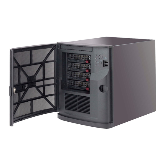
Chapter 1: Introduction 1.3 Chassis Features Front Features The SC721TQ-250B is a compact Mini Tower chassis. The front of the chassis includes a power on/off push-button, a reset button and several LEDs as described below. Figure 1-1. Chassis Front View Front Chassis Features Item Feature... -
Page 10: Rear Features
SuperServer 5029AP-TN2 User's Manual Information LED Status Description An overheat condition has occured. Continuously on and red (This may be caused by cable congestion.) Blinking red (1Hz) Fan failure, check for an inoperative fan. Rear Features The rear of the chassis has various input/output ports. -
Page 11: Motherboard Layout
Chapter 1: Introduction 1.4 Motherboard Layout Jumper, connector and LED locations are shown below with brief descriptions on the following page. Detailed descriptions are found in Chapter 4. COM1 JPL2 USB2/3 (3.0) JPL1 USB8/9 LAN2 USB0/1 HDMI/DP LAN1 AUDIO FP AUDIO JPL2 JPL1... -
Page 12: Quick Reference Table
SuperServer 5029AP-TN2 User's Manual Quick Reference Table Jumper Description Default Setting JBT1 CMOS Clear Open: Normal, Short: Clear CMOS C1/JI SMB to PCI-E Slots Enable/Disable Pins 1-2 (Enabled) JPAC1 Audio Enable/Disable Pins 1-2 (Enabled) JPL1 LAN1 Enable/Disable Pins 1-2 (Enabled) -
Page 13: System Block Diagram
Chapter 1: Introduction System Block Diagram DDI0 HDMI connector Intel DDI1 DP connector For Booting up, should DDR3L non ECC SKU eDP switch pop in Channe0 EDP connector DUAL CHANNEL Non-ECC-SODIMM0 DDR3L 1867 MHz VGA connector MAX. 8G SO-DIMM SUPPORTED FLASH REALTEK FST_SPI... -
Page 14: Chapter 2 Maintenance And Component Installation
SuperServer 5029AP-TN2 User's Manual Chapter 2 Maintenance and Component Installation This chapter provides instructions on installing and replacing main system components. To prevent compatibility issues, only use components that match the specifications and/or part numbers given. Installation or replacement of most components requires that power first be removed from the system. -
Page 15: Rear Chassis Hasp
Chapter 2 Maintenance and Component Installation Figure 2-1. Front Bezel Lock Rear Chassis Hasp Unauthorized entry through the rear of the chassis may be discouraged by placing a lock on the rear of the chassis. The chassis is equipped with a rear chassis hasp that can accomodate a variety of commonly available locks (not included). -
Page 16: Accessing The System
SuperServer 5029AP-TN2 User's Manual 2.3 Accessing the System The SC721TQ-250B features a removable top cover to access to the inside of the chassis. Figure 2-4. Removing the Chassis Cover Removing the Top Cover 1. Power down the system as described in section 2.1. -
Page 17: Motherboard Components
Memory Support The motherboard supports up to 8 GB of DDR3L Dual Non-ECC SO-DIMM of speeds up to 1866 MHz in one low-profile slot. Check the Supermicro website for a list of memory modules that have been validated. Installing Memory Caution: Exercise extreme care when installing or removing DIMM modules to prevent damage. -
Page 18: Ssd
SuperServer 5029AP-TN2 User's Manual M.2 SSD The A2SAV supports one M.2 SSD of 120mm in length. Visit the Supermicro website for a current list of supported M.2 SSDs. Note: installing an M.2 SSD card will disable I-SATA0. Installing an M.2 SSD 1. -
Page 19: Installing Expansion Cards
Chapter 2 Maintenance and Component Installation Installing Expansion Cards The 5029AP-TN2 includes a PCI slot for a low-profile expansion card. The card is installed by removing the chassis tray that holds the motherboard and rear I/O shield. Installing an Expansion Card 1. - Page 20 SuperServer 5029AP-TN2 User's Manual 4. Remove the screw that secures the PCI slot shield in the PCI slot at the rear of the tray and set it aside for later use. 5. Slide the PCI slot shield up and out of the PCI slot.
-
Page 21: Motherboard Battery
Chapter 2 Maintenance and Component Installation Motherboard Battery The motherboard uses non-volatile memory to retain system information when system power is removed. This memory is powered by a lithium battery residing on the motherboard. LITHIUM BATTERY BATTERY HOLDER Figure 2-8. Installing the Onboard Battery Replacing the Battery 1. -
Page 22: Chassis Components
SuperServer 5029AP-TN2 User's Manual 2.5 Chassis Components Front-Mounted Hot-Swap Drives The SC721TQ-250B supports four hot-swappable drives mounted in carriers that are accessible from the front of the chassis. These drives may be removed and installed without powering down the system. - Page 23 Chapter 2 Maintenance and Component Installation Hard Drive Dummy Drive Hard Drive Carrier Figure 2-10. Installing a Hard Drive into a Drive Carrier Installing a Drive Carrier into the Hard Drive Cage 1. Insert the hard drive carrier into the drive bay, using the drive carrier handle to push it all the way into the hard drive cage until it stops.
-
Page 24: Installing The Internal Fixed Hard Drives
SuperServer 5029AP-TN2 User's Manual Installing the Internal Fixed Hard Drives The SC721TQ-250B chassis supports two internal 2.5" SATA fixed hard drives: one top- mounted drive and one side-mounted drive. Installing a Top-Mounted Fixed Hard Drive 1. Power down the system as described in Section 2.1 and remove the chassis cover. - Page 25 Chapter 2 Maintenance and Component Installation Installing a Side-Mounted Fixed Hard Drive 1. Power down the system as described in Section 2.1 and remove the chassis cover. 2. Place a 2.5" hard drive into the hard drive bracket and secure the hard drive to the bracket with the four screws provided.
-
Page 26: Installing A Dvd Drive
SuperServer 5029AP-TN2 User's Manual Installing a DVD Drive The SC721TQ-250B supports one DVD drive. It can be installed only if the top mounted fixed HDD is not used. It requires a mounting bracket rail (p/n MCP-220-81502-0N). Installing a DVD Drive 1. - Page 27 Chapter 2 Maintenance and Component Installation 7. Install the bracket rail (part number MCP-220-81502-0N) onto the left hand side of the DVD drive, using the two screws provided. Bracket Rail Figure 2-15. Securing the Bracket Rail to a DVD Drive 8.
-
Page 28: Installing A Fan
SuperServer 5029AP-TN2 User's Manual Installing a Fan The chassis includes a single 12-cm rear exhaust fan. The chassis also features a set of mounting holes that will support a standard 9-cm exhaust fan (not included). Installing the Exhasut Fan 1. Power down the system as described in Section 2.1 and remove the chassis cover. -
Page 29: Replacing The Power Supply
Chapter 2 Maintenance and Component Installation Replacing the Power Supply The SC721TQ-250B includes a fixed (non-hot-swap) 250W power supply. If it is necessary to replace the power supply, follow the instructions below. Changing the Power Supply 1. Power down the system as described in Section 2.1 and remove the chassis cover. 2. -
Page 30: Chapter 3 Motherboard Connections
SuperServer 5029AP-TN2 User's Manual Chapter 3 Motherboard Connections This section describes the connections on the A2SAV motherboard and provides pinout definitions. Note that depending on how the system is configured, not all connections are required. The LEDs on the motherboard are also described here. A motherboard layout indicating component locations may be found in Chapter 1. - Page 31 Chapter 3: Motherboard Connections 4-pin 12V Power Connector JPV1 is the 12V DC power connector that provides an alternative single power source for special enclosure when the 24-pin ATX power is not in use. +12V 4-pin Power Pin Definitions Pin# Definition 1 - 2 Ground...
-
Page 32: Headers And Connectors
SuperServer 5029AP-TN2 User's Manual 3.2 Headers and Connectors Fan Headers There are two 4-pin fan headers on the motherboard. Although pins 1-3 of the fan headers are backward compatible with traditional 3-pin fans, we recommend you use 4-pin fans to take advantage of the fan speed control via Pulse Width Modulation through the BMC. - Page 33 Chapter 3: Motherboard Connections TPM Header The JTPM1 header is used to connect a Trusted Platform Module (TPM), which is available from a third-party vendor. A TPM is a security device that supports encryption and authentication in hard drives. It enables the motherboard to deny access if the TPM associated with the hard drive is not installed in the system.
- Page 34 SuperServer 5029AP-TN2 User's Manual Audio Front Panel Header A 10-pin audio header located on the motherboard allows you to use the onboard sound chip (ALC888S) for audio function. Connect an audio cable to the this header to use this feature.
- Page 35 Chapter 3: Motherboard Connections Mini PCI-E Slot The Mini PCI-E slot is used to install a compatible Mini PCI-E device. The slot supports mSATA and is Mux with I-SATA1. The mSATA feature leverages the speed and reliability of the SATA interface to provide a high performance, cost-effective storage solution for smaller devices like notebooks and netbooks.
-
Page 36: Control Panel Header
SuperServer 5029AP-TN2 User's Manual Control Panel Header JF1 contains header pins for various control panel connections. See the figure below for the pin locations and definitions of the control panel buttons and LED indicators. All JF1 wires have been bundled into a single cable to simplify this connection. Make sure the red wire plugs into pin 1 as marked on the motherboard. - Page 37 Chapter 3: Motherboard Connections Fan Fail Connect an LED cable to Fan Fail connections on pins 7 and 8 of JF1 to provide warnings for chassis overheat/fan failure. Fan Fail Indicator Fan Fail LED Status Pin Definitions (JF1) Pin# Definition Pins Definition Normal...
-
Page 38: Ports
SuperServer 5029AP-TN2 User's Manual 3.3 Ports Figure 3-2. Rear input/Output Ports Rear I/O Ports Description Description DisplayPort USB1 Port (USB 2.0) HDMI Port USB0 Port (USB 2.0) COM1 Port LAN1 Port USB2 Port (USB 3.0) LAN2 Port USB3 Port (USB 3.0) -
Page 39: Jumpers
Chapter 3: Motherboard Connections 3.4 Jumpers Explanation of Jumpers To modify the operation of the motherboard, jumpers are used to choose between optional settings. Jumpers create shorts between two pins to change the function associated with it. Pin 1 is identified with a square solder pad on the printed circuit board. See the motherboard layout page for jumper locations. - Page 40 SuperServer 5029AP-TN2 User's Manual Manufacturing Mode Select Close JPME2 to bypass SPI flash security and force the system to use the Manufacture Mode, which will allow you to flash the system firmware from a host server to modify system settings. The default setting is Normal.
-
Page 41: Led Indicators
Chapter 3: Motherboard Connections 3.5 LED Indicators LAN1, LAN2 LEDs The Ethernet ports each have two LEDs. The Activity LED indicates network activity when flashing. The Link LED may be green, amber or off to indicate the speed of the connection. LAN 1/LAN 2 LAN1/2 LEDs (Connection Speed Indicator) -
Page 42: Chapter 4 Software
This section describes the installation of drivers and management programs for the system. 4.1 Driver Installation The Supermicro FTP site contains drivers and utilities for your system at ftp://ftp.supermicro. com. Some of these must be installed, such as the chipset driver. -
Page 43: Superdoctor ® 5
4.2 SuperDoctor ® The Supermicro SuperDoctor 5 is a program that functions in a command-line or web-based interface for Windows and Linux operating systems. The program monitors such system health information as CPU temperature, system voltages, system power consumption, fan speed, and provides alerts via email or Simple Network Management Protocol (SNMP). -
Page 44: Chapter 5 Bios
SuperServer 5029AP-TN2 User's Manual Chapter 5 BIOS 5.1 Introduction This chapter describes the AMI BIOS setup utility for the A2SAV and provides the instructions on navigating the setup screens. The BIOS is stored in a Flash EEPROM and can be updated. - Page 45 HH:MM:SS format. Note: The time is in the 24-hour format. For example, 5:30 P.M. appears as 17:30:00. The date's default value is 01/01/2016 after RTC reset. Supermicro A2SAV (Motherboard model) BIOS Version Build Date (of the BIOS) CPLD (Complex Programmable Logic Device) Version: This item displays the CPLD version used in the system.
-
Page 46: Advanced Setup Configurations
SuperServer 5029AP-TN2 User's Manual 5.3 Advanced Setup Configurations Use the arrow keys to select the Advanced tab and press <Enter> to access the submenu items. Caution: Take caution when changing the Advanced settings. An incorrect value, a very high DRAM frequency, or an incorrect DRAM timing setting may make the system unstable. If this occurs, revert to the manufacture default settings. - Page 47 Chapter 5: BIOS Wait For "F1" If Error This feature forces the system to wait until the 'F1' key is pressed if an error occurs. The options are Disabled and Enabled. INT19 Capture Trap Response Interrupt 19 is the software interrupt that handles the boot disk function. When this item is set to Immediate, the ROM BIOS of the host adaptors will "capture"...
- Page 48 SuperServer 5029AP-TN2 User's Manual CPU Configuration The following CPU information appears: • Displays the CPU model • CPU Signature • Microcode Patch • Max CPU Speed • Min CPU Speed • Processor Cores • Intel HT Technology • Intel VT-x Technology •...
- Page 49 Chapter 5: BIOS Power Limit 1 Enable Use this feature to set the power limit for the CPU. The options are Disable and Enable. Power Limit 1 Power Limit 1 Clamp Mode Use this feature to set the PL1 clamp bit. The options are Disable and Enable. Power Limit 1 Power Use this item to configure the value for Power Limit 1.
- Page 50 SuperServer 5029AP-TN2 User's Manual P-State coordination type for all software installed in the system. Select SW_ANY to change the P-State coordination type for a software program in the system. The options are HW_All, SW_ALL, and SW_ANY. Chipset Warning: Setting the wrong values in the following sections may cause the system to malfunc- tion.
- Page 51 Chapter 5: BIOS GTT Size Use this feature to set the memory size to be used by the graphics translation table (GTT). The options are 2MB, 4MB, and 8MB. Aperture Size Use this feature to set the Aperture size, which is the size of system memory reserved by the BIOS for graphics device use.
- Page 52 SuperServer 5029AP-TN2 User's Manual system configuration. Select Disabled to disable ASPM support. The options are Disable, L0s, L1, L0sL1, and Auto. PCIe Speed Uses this feature to select the PCI speed for the device installed in slot 1. The options are Auto, Gen1, and Gen2.
- Page 53 Chapter 5: BIOS SATA Mode Selection Use this item to select the mode for the installed SATA drives. The options are AHCI and RAID. Aggressive LPM (Link Power Management) Support When this item is set to Enabled, the SATA AHCI controller manages the power usage of the SATA link.
- Page 54 SuperServer 5029AP-TN2 User's Manual TPM State This feature changes the TPM State. The options are Disabled and Enabled. Note: The system will restart to change the TPM State. Pending TPM operation Use this item to schedule a TPM-related operation to be performed by a security device for system data integrity.
- Page 55 Chapter 5: BIOS Device Settings This item displays the base I/O port address and the Interrupt Request address of a serial port specified by the user. Change Port 1 Settings This feature specifies the base I/O port address and the Interrupt Request address of Serial Port 1.
- Page 56 SuperServer 5029AP-TN2 User's Manual The options for Serial Port 2 are Auto, (IO=3E8h; IRQ=7), (IO=3E8h; IRQ=3, 4, 5, 6, 7, 9, 10, 11, 12), (IO=2E8h; IRQ=3, 4, 5, 6, 7, 9, 10, 11, 12), (IO=2F0h; IRQ=3, 4, 5, 6, 7, 9, 10, 11, 12), and (IO=2E0h;...
- Page 57 Chapter 5: BIOS COM1 Bits Per second Use this feature to set the transmission speed for a serial port used in Console Redirection. Make sure that the same speed is used in the host computer and the client computer. A lower transmission speed may be required for long and busy lines.
- Page 58 SuperServer 5029AP-TN2 User's Manual COM1 Putty KeyPad This feature selects the settings for Function Keys and KeyPad used for Putty, which is a terminal emulator designed for the Windows OS. The options are VT100, LINUX, XTERMR6, SC0, ESCN, and VT400.
- Page 59 Chapter 5: BIOS Odd if the parity bit is set to 0, and the number of 1's in data bits is odd. Select None if you do not want to send a parity bit with your data bits in transmission. Select Mark to add a mark as a parity bit to be sent along with the data bits.
- Page 60 SuperServer 5029AP-TN2 User's Manual EMS (Emergency Management Services) Console Redirection Select Enabled to use a COM port selected by the user for EMS Console Redirection. The options are Enabled and Disabled. *If the item above set to Enabled, the following items will become available for user's configuration: EMS Console Redirection Settings...
- Page 61 Chapter 5: BIOS PCIe/PCI/PnP Configuration PCI Bus Driver Version A5.01.08 PCI Devices Common Settings: Above 4G Decoding Select Enabled for 64-bit devices to be decoded above the 4GB address space If 64bit PCI decoding is supported by the system. The options are Disabled and Enabled. CPU SLOT1 PCI-E 2.0 X2 (INX8) OPROM Use this feature to select the type of firmware to be loaded for the device installed on this slot.
- Page 62 SuperServer 5029AP-TN2 User's Manual Media detect count Use this option to specify the number of times media will be checked. Press "+" or "-" on your keyboard to change the value. The default setting is 1. iSCSi Configuration iSCSI Initiator Name This feature allows the user to enter the unique name of the iSCSI Initiator in IQN format.
- Page 63 Chapter 5: BIOS PCI Device ID This item displays the device ID number. PCI Address This item displays the PCI address for this computer. PCI addresses are three two-digit hexadecimal numbers. Link Status This item displays the connection status. MAC Address This item displays the MAC address for this computer.
- Page 64 SuperServer 5029AP-TN2 User's Manual Chip Type This item displays the network adapter chipset name. PCI Device ID This item displays the device ID number. PCI Address This item displays the PCI address for this computer. PCI addresses are three two-digit hexadecimal numbers.
-
Page 65: Security
Chapter 5: BIOS 5.4 Security Use this tab page to configure Security settings. This menu allows the user to configure Security settings. Password Check Use this feature to determine when a password entry is required. Select Setup to require the password only when entering setup. - Page 66 SuperServer 5029AP-TN2 User's Manual Secure Boot Mode This feature allows the user to select the desired secure boot mode for the system. The options are Standard and Customized. If Secure Boot Mode is set to Customized, Key Management features will be available for configuration: ...
- Page 67 Chapter 5: BIOS Append Key Select Yes to add the database from the manufacturer's defaults to the existing DB. Select No to load the DB from a file. The options are Yes and No. Forbidden Signatures Set New Key Select Yes to load the DBX from the manufacturer's defaults.
-
Page 68: Boot
SuperServer 5029AP-TN2 User's Manual 5.5 Boot Use this tab page to configure Boot Settings. Fixed Boot Order Priorities This option prioritizes the order of bootable devices that the system can boot from. Press <Enter> on each entry from top to bottom to select devices. - Page 69 Chapter 5: BIOS UEFI Application Boot Priorities This feature allows the user to specify which UEFI devices are boot devices. • UEFI Boot Order #1 UEFI USB Key Drive BBS Priorities This feature allows the user to specify which UEFI USB Key drive devices are boot devices. This feature is displayed when a storage device is detected.
-
Page 70: Save & Exit
SuperServer 5029AP-TN2 User's Manual 5.6 Save & Exit Use this tab page to configure Save & Exit settings. Save Options Discard Changes and Exit Select this option to quit the BIOS Setup without making any permanent changes to the system configuration, and reboot the computer. Select Discard Changes and Exit from the Exit menu and press <Enter>. - Page 71 Chapter 5: BIOS Default Options Restore Defaults To set this feature, select Restore Defaults from the Exit menu and press <Enter>. These are factory settings designed for maximum system performance but not for maximum stability. Save as User Defaults To set this feature, select Save as User Defaults from the Exit menu and press <Enter>. This enables the user to save any changes to the BIOS setup for future use.
-
Page 72: Appendix A Bios Codes
SuperServer 5029AP-TN2 User's Manual Appendix A BIOS Codes A.1 BIOS Error POST (Beep) Codes During the POST (Power-On Self-Test) routines, which are performed each time the system is powered on, errors may occur. Non-fatal errors are those which, in most cases, allow the system to continue the boot-up process. - Page 73 When BIOS performs the Power On Self Test, it writes checkpoint codes to I/O port 0080h. If the computer cannot complete the boot process, a diagnostic card can be attached to the computer to read I/O port 0080h (Supermicro p/n AOC-LPC80-20). For information on AMI updates, please refer to http://www.ami.com/products/.
-
Page 74: Appendix B Standardized Warning Statements For Ac Systems
Supermicro's Technical Support department for assistance. Only certified technicians should attempt to install or configure components. Read this appendix in its entirety before installing or configuring components in the Supermicro chassis. These warnings may also be found on our website at http://www.supermicro.com/about/... - Page 75 Appendix B: Standardized Warning Statements Warnung WICHTIGE SICHERHEITSHINWEISE Dieses Warnsymbol bedeutet Gefahr. Sie befinden sich in einer Situation, die zu Verletzungen führen kann. Machen Sie sich vor der Arbeit mit Geräten mit den Gefahren elektrischer Schaltungen und den üblichen Verfahren zur Vorbeugung vor Unfällen vertraut. Suchen Sie mit der am Ende jeder Warnung angegebenen Anweisungsnummer nach der jeweiligen Übersetzung in den übersetzten Sicherheitshinweisen, die zusammen mit diesem Gerät ausgeliefert wurden.
- Page 76 SuperServer 5029AP-TN2 User's Manual جسذٌة اصابة ًتتسبب ف حالة ٌوكي أى ًاًك ف خطز ًٌٌع هذا الزهز !تحذٌز الذوائز بالوخاطز الٌاجوة عي ي على علن ، ك هعذات تعول على أي قبل أى الكهزبائٍة حىادث أي وقىع وٌع ل الىقائٍة...
- Page 77 Appendix B: Standardized Warning Statements Warnung Vor dem Anschließen des Systems an die Stromquelle die Installationsanweisungen lesen. ¡Advertencia! Lea las instrucciones de instalación antes de conectar el sistema a la red de alimentación. Attention Avant de brancher le système sur la source d'alimentation, consulter les directives d'installation. מתח...
- Page 78 SuperServer 5029AP-TN2 User's Manual Warnung Dieses Produkt ist darauf angewiesen, dass im Gebäude ein Kurzschluss- bzw. Überstromschutz installiert ist. Stellen Sie sicher, dass der Nennwert der Schutzvorrichtung nicht mehr als: 250 V, 20 A beträgt. ¡Advertencia! Este equipo utiliza el sistema de protección contra cortocircuitos (o sobrecorrientes) del edificio.
- Page 79 Appendix B: Standardized Warning Statements Power Disconnection Warning Warning! The system must be disconnected from all sources of power and the power cord removed from the power supply module(s) before accessing the chassis interior to install or remove system components. 電源切断の警告...
- Page 80 SuperServer 5029AP-TN2 User's Manual امداد وحدة من سهك انكهرباء وإزانت انطاقت مصادر من جميع اننظاو يجب فصم قبم انطاقت الجهاز مكىناث نتثبيج أو إزانت ههيكم ن انمناطق انداخهيت انىصىل إنى 경고! 시스템에 부품들을 장착하거나 제거하기 위해서는 섀시 내부에 접근하기 전에 반드시 전원...
- Page 81 Appendix B: Standardized Warning Statements Attention Il est vivement recommandé de confier l'installation, le remplacement et la maintenance de ces équipements à des personnels qualifiés et expérimentés. !אזהרה .הציוד או לתת שירות עבור הציוד אי להתקין, להחליף את צוות מוסמך בלבד רש هذا...
- Page 82 SuperServer 5029AP-TN2 User's Manual Warnung Diese Einheit ist zur Installation in Bereichen mit beschränktem Zutritt vorgesehen. Der Zutritt zu derartigen Bereichen ist nur mit einem Spezialwerkzeug, Schloss und Schlüssel oder einer sonstigen Sicherheitsvorkehrung möglich. ¡Advertencia! Esta unidad ha sido diseñada para instalación en áreas de acceso restringido. Sólo puede obtenerse acceso a una de estas áreas mediante la utilización de una herramienta especial,...
- Page 83 Appendix B: Standardized Warning Statements Battery Handling Warning! There is the danger of explosion if the battery is replaced incorrectly. Replace the battery only with the same or equivalent type recommended by the manufacturer. Dispose of used batteries according to the manufacturer's instructions 電池の取り扱い...
- Page 84 SuperServer 5029AP-TN2 User's Manual فعليل بطريقة غير صحيحة البطارية انفجار في حالة اسحبذال من هناك خطر اسحبذال البطارية به الشرمة المصنعة أوصث مما أو ما يعادلها بنفس النىع فقط حعليمات الشرمة الصانعة المسحعملة وفقا ل جخلص من البطاريات 경고! 배터리가 올바르게 교체되지 않으면 폭발의 위험이 있습니다. 기존 배터리와 동일하거나 제...
- Page 85 Appendix B: Standardized Warning Statements ¡Advertencia! Puede que esta unidad tenga más de una conexión para fuentes de alimentación. Para cortar por completo el suministro de energía, deben desconectarse todas las conexiones. Attention Cette unité peut avoir plus d'une connexion d'alimentation. Pour supprimer toute tension et tout courant électrique de l'unité, toutes les connexions d'alimentation doivent être débranchées.
- Page 86 SuperServer 5029AP-TN2 User's Manual Backplane Voltage Warning! Hazardous voltage or energy is present on the backplane when the system is operating. Use caution when servicing. バックプレーンの電圧 システムの稼働中は危険な電圧または電力が、 バックプレーン上にかかっています。 修理する際には注意く ださい。 警告 当系统正在进行时,背板上有很危险的电压或能量,进行维修时务必小心。 警告 當系統正在進行時,背板上有危險的電壓或能量,進行維修時務必小心。 Warnung Wenn das System in Betrieb ist, treten auf der Rückwandplatine gefährliche Spannungen oder Energien auf.
- Page 87 Appendix B: Standardized Warning Statements اللىحة أوالطاقة المىجىدة على التيار الكهزبائي مه خطز هناك هذا الجهاس خدمة كه حذرا عند يعمل النظام عندما يكىن 경고! 시스템이 동작 중일 때 후면판 (Backplane)에는 위험한 전압이나 에너지가 발생 합니다. 서비스 작업 시 주의하십시오. Waarschuwing Een gevaarlijke spanning of energie is aanwezig op de backplane wanneer het systeem in gebruik is.
- Page 88 SuperServer 5029AP-TN2 User's Manual תיאום חוקי החשמל הארצי !אזהרה הציוד חייבת להיות תואמת לחוקי החשמל המקומיים והארציים התקנת المتعلقة المحلية والىطىية قىاويه يجب أن يمتثل لل الكهربائية تركيب المعدات بالكهرباء 경고! 현 지역 및 국가의 전기 규정에 따라 장비를 설치해야 합니다.
- Page 89 Appendix B: Standardized Warning Statements Attention La mise au rebut ou le recyclage de ce produit sont généralement soumis à des lois et/ou directives de respect de l'environnement. Renseignez-vous auprès de l'organisme compétent. סילוק המוצר !אזהרה .חוקי המדינה סילוק סופי של מוצר זה חייב להיות בהתאם להנחיות ו القىانين...
- Page 90 SuperServer 5029AP-TN2 User's Manual Warnung Gefährlich Bewegende Teile. Von den bewegenden Lüfterblätter fern halten. Die Lüfter drehen sich u. U. noch, wenn die Lüfterbaugruppe aus dem Chassis genommen wird. Halten Sie Finger, Schraubendreher und andere Gegenstände von den Öffnungen des Lüftergehäuses entfernt.
- Page 91 Brand entstehen. Elektrische Geräte und Material Safety Law verbietet die Verwendung von UL-oder CSA-zertifizierte Kabel, UL oder CSA auf der Code für alle anderen elektrischen Geräte als Produkte von Supermicro nur bezeichnet gezeigt haben. ¡Advertencia! Al instalar el producto, utilice los cables de conexión previstos o designados, los cables y adaptadores de CA.
- Page 92 Het gebruik van andere kabels en adapters kan leiden tot een storing of een brand. Elektrisch apparaat en veiligheidsinformatiebladen wet verbiedt het gebruik van UL of CSA gecertificeerde kabels die UL of CSA die op de code voor andere elektrische apparaten dan de producten die door Supermicro alleen.
-
Page 93: Appendix C System Specifications
Appendix C: System Specifications Appendix C System Specifications Processors Single Intel Atom E3940 Quad Core SoC in an FCBGA 1296 type socket Note: Please refer to the motherboard specifications pages on our website for updates to supported processors. Chipset BIOS 64Mb SPI Flash EEPROM with AMI UEFI BIOS Memory One 204-pin SO-DIMM slot supporting up to 8 GB of non-ECC DDR3-1866/1600/1333 memory... - Page 94 SuperServer 5029AP-TN2 User's Manual Regulatory Compliance Electromagnetic Emissions: FCC Class B, EN 55022 Class B, EN 61000-3-2/3-3, CISPR 22 Class B Electromagnetic Immunity: EN 55024/CISPR 24, (EN 61000-4-2, EN 61000-4-3, EN 61000-4-4, EN 61000-4-5, EN 61000-4-6, EN 61000-4-8, EN 61000-4-11) Safety: CSA/EN/IEC/UL 60950-1 Compliant, UL or CSA Listed (USA and Canada), CE Marking (Europe) 1.
Need help?
Do you have a question about the SuperServer 5029AP-TN2 and is the answer not in the manual?
Questions and answers