Table of Contents
Advertisement
Quick Links
Advertisement
Table of Contents

Related Manuals for Supermicro Supero SUPERSERVER 5086B-TRF


Summary of Contents for Supermicro Supero SUPERSERVER 5086B-TRF
- Page 1 UPER ® UPER ERVER 5086B-TRF USER’S MANUAL...
- Page 2 This product, including software and docu- mentation, is the property of Supermicro and/or its licensors, and is supplied only under a license. Any use or reproduction of this product is not allowed, except as expressly permitted by the terms of said license.
-
Page 3: About This Manual
Preface Preface About This Manual This manual is written for professional system integrators and PC technicians. It pro- vides information for the installation and use of the SuperServer 5086B-TRF. Instal- lation and maintainance should be performed by experienced technicians only. The SuperServer 5086B-TRF is a high-density, 5U 8-way server solution housed in the SC758 rackmount chassis. - Page 4 UPER ERVER 5086B-TRF User's Manual Chapter 5: Advanced Setup Chapter 5 provides detailed information on the X8OBN-F baseboard as well as the CPU boards (X8OBN-CPU) and bridge boards (X8OBN-BR1, and includes the locations and functions of connections, headers and jumpers. Refer to this chapter when adding or removing processors or main memory.
- Page 5 Preface Notes...
-
Page 6: Table Of Contents
Server Chassis Features ................1-4 System Power ....................1-4 Hard Drives ..................... 1-4 Front Control Panel ..................1-4 Cooling System ....................1-4 Contacting Supermicro ..................1-5 Chapter 2 Server Installation Overview ......................2-1 Unpacking the System ..................2-1 Preparing for Setup ..................2-1 Choosing a Setup Location ................ - Page 7 Table of Contents Checking the Confi guration ................2-10 Checking the Drive Bay Setup ...............2-11 Chapter 3 System Interface Overview ......................3-1 Control Panel Buttons ..................3-1 Reset ....................... 3-1 Power ......................3-1 Control Panel LEDs ..................3-1 Power Fail ....................... 3-2 Overheat/Fan Fail: ..................
- Page 8 UPER ERVER 5086B-TRF User's Manual Onboard Indicators ..................5-20 I/O Ports ......................5-21 Serial ATA Connections ................. 5-21 5-10 Installing Software ..................5-22 SuperDoctor III ....................5-23 Chapter 6 Advanced Chassis Setup Static-Sensitive Devices .................. 6-1 Precautions ..................... 6-1 Unpacking ....................... 6-1 Control Panel ....................
-
Page 9: Chapter 1 Introduction
X8OBN-BR1 bridge boards. Please refer to our web site for information on operating systems that have been certifi ed for use with the system (www.supermicro.com). Below is a list of the main hardware components included with the 5086B-TRF: •... -
Page 10: Baseboard And Cpu Board Features
8-core processors and next generation Xeon E7 8800 family 10-core processors. Please refer to the product page on our web site for a complete listing of supported processors (www.supermicro.com). Memory The four X8OBN-CPU boards in the system have a total of 64 DIMM slots that can support up to 2 TB of ECC registered DDR3-1333/1066/978/800 SDRAM. - Page 11 Chapter 1: Introduction Figure 1-1. Intel 7500 + ICH10R Chipset: System Block Diagram Note: This is a general block diagram. Please see Chapter 5 for details.
-
Page 12: Server Chassis Features
UPER ERVER 5086B-TRF User's Manual Server Chassis Features System Power The SC758 features four Gold Level 1400W power supply power modules (2+2 redundancy) to provide 2800W of uninterrupted power. This power redundancy feature also allows you to replace a failed power module without shutting down the system. -
Page 13: Contacting Supermicro
Super Micro Computer, Inc. 980 Rock Ave. San Jose, CA 95131 U.S.A. Tel: +1 (408) 503-8000 Fax: +1 (408) 503-8008 Email: marketing@supermicro.com (General Information) support@supermicro.com (Technical Support) Web Site: www.supermicro.com Europe Address: Super Micro Computer B.V. Het Sterrenbeeld 28, 5215 ML... - Page 14 UPER ERVER 5086B-TRF User's Manual Notes...
-
Page 15: Chapter 2 Server Installation
Chapter 2: Server Installation Chapter 2 Server Installation Overview This chapter provides a quick setup checklist to get your SuperServer 5086B-TRF up and running. Following these steps in the order given should enable you to have the system operational within a minimum amount of time. This quick setup assumes that your system has come to you with the processors and memory preinstalled. -
Page 16: Choosing A Setup Location
UPER ERVER 5086B-TRF User's Manual Choosing a Setup Location • Leave enough clearance in front of the rack to enable you to open the front door completely (~25 inches) and approximately 30 inches of clearance in the back of the rack to allow for suffi cient airfl ow and ease in servicing. •... -
Page 17: Rack Mounting Considerations
Chapter 2: Server Installation • Allow the hot plug SATA drives and power supply modules to cool before touch- ing them. • Always keep the rack's front door and all panels and components on the servers closed when not servicing to maintain proper cooling. Rack Mounting Considerations Ambient Operating Temperature If installed in a closed or multi-unit rack assembly, the ambient operating tempera-... -
Page 18: Installing The System Into A Rack
UPER ERVER 5086B-TRF User's Manual Installing the System into a Rack This section provides information on installing the system into a rack unit. Rack installation requires the use of a rackmount kit. If the system has already been mounted into a rack or if you are using it as a tower, you can skip ahead to Sec- tions 2-5 and 2-6. -
Page 19: Locking Tabs
Chapter 2: Server Installation Locking Tabs Each inner rail has a locking tab. This tab locks the chassis into place when installed and pushed fully into the rack. These tabs also lock the chassis in place when fully extended from the rack. This prevents the server from coming completely out of the rack when when the chassis is pulled out for servicing. -
Page 20: Installing The Inner Rails On The Chassis
UPER ERVER 5086B-TRF User's Manual Installing The Inner Rails on the Chassis Installing the Inner Rails Confi rm that the left and right inner rails have been correctly identifi ed. Place the inner rail fi rmly against the side of the chassis, aligning the hooks on the side of the chassis with the holes in the inner rail. -
Page 21: Installing The Outer Rails On The Rack
Chapter 2: Server Installation Installing the Outer Rails on the Rack Installing the Outer Rails Press upward on the locking tab at the rear end of the middle rail. Push the middle rail back into the outer rail. Hang the hooks of the front of the outer rail onto the slots on the front of the rack. - Page 22 UPER ERVER 5086B-TRF User's Manual Installing the Chassis into a Rack Confi rm that the inner rails are properly installed on the chassis. Confi rm that the outer rails are correctly installed on the rack. Pull the middle rail out from the front of the outer rail and make sure that the ball-bearing shuttle is at the front locking position of the middle rail.
-
Page 23: Optional Quick Installation Method
Chapter 2: Server Installation Optional Quick Installation Method The following quick installation method may be used to install the chassis into a rack. Install the whole rail assembly onto the rack as described on page X-7. Release the inner rail without retracting the middle rail. Install the inner rails on the chassis as previously described on page X-6. -
Page 24: Checking The Confi Guration
UPER ERVER 5086B-TRF User's Manual Checking the Confi guration After setting up the the system, you will need to open the unit to make sure the various boards are properly installed and all the connections have been made. Accessing the Inside of the System If rack mounted, fi... -
Page 25: Checking The Drive Bay Setup
Chapter 2: Server Installation Checking the Drive Bay Setup Next, you should check to make sure the peripheral drives and the SATA drives and backplane have been properly installed and all connections have been made. Checking the Drives All drives can be accessed from the front of the server. For servicing the pe- ripheral drives, you will need to remove the top/left chassis cover. - Page 26 UPER ERVER 5086B-TRF User's Manual Notes 2-12...
-
Page 27: Chapter 3 System Interface
Chapter 3: System Interface Chapter 3 System Interface Overview There are several LEDs on two control panels as well as others on the drive carri- ers to keep you constantly informed of the overall status of the system as well as the activity and health of specifi... -
Page 28: Power Fail
SUPERSERVER 5086B-TRF User's Manual Power Fail Indicates a power supply module has failed. The backup power supply module will take the load and keep the system running but the failed module will need to be replaced. Refer to Chapter 6 for details on replacing the power supply. This LED should be off when the system is operating normally. -
Page 29: Power
Chapter 3: System Interface Power Indicates power is being supplied to the system's power supply units. This LED should normally be illuminated when the system is operating. Drive Carrier LEDs Each drive carrier has two LEDs: • Green: This LED will blink on and off to indicate read/write activity to the hard drive. - Page 30 SUPERSERVER 5086B-TRF User's Manual Notes...
-
Page 31: Chapter 4 System Safety
Chapter 4: System Safety Chapter 4 System Safety Electrical Safety Precautions Basic electrical safety precautions should be followed to protect yourself from harm and the SuperServer 5086B-TRF from damage: • Be aware of the locations of the power on/off switch on the chassis as well as the room's emergency power-off switch, disconnection switch or electrical outlet. -
Page 32: General Safety Precautions
UPER ERVER 5086B-TRF User's Manual • This product may be connected to an IT power system. In all cases, make sure that the unit is also reliably connected to Earth (ground). • Baseboard Battery: CAUTION - There is a danger of explosion if the onboard battery is installed upside down, which will reverse its polarites (see Figure 4-1). -
Page 33: Esd Precautions
Chapter 4: System Safety • Remove any jewelry or metal objects from your body, which are excellent metal conductors that can create short circuits and harm you if they come into contact with printed circuit boards or areas where power is present. •... -
Page 34: Operating Precautions
UPER ERVER 5086B-TRF User's Manual Operating Precautions Care must be taken to assure that the chassis cover is in place when the 5086B- TRF is operating to assure proper cooling. Out of warranty damage to the system can occur if this practice is not strictly followed. Figure 4-1. -
Page 35: Chapter 5 Advanced Setup
Chapter 5: Advanced Setup Chapter 5 Advanced Setup This chapter provides detailed information on the X8OBN-F baseboard and the boards that install into it. All jumpers and connections are described. A layout and quick reference chart are also included in this chapter for your reference. Remember to completely close the chassis when you have fi... -
Page 36: Component Installation
UPER ERVER 5086B-TRF User's Manual Component Installation The 5086B-TRF has a unique design that sets it apart from most server systems. Processors are installed into four CPU boards, which are installed to a baseboard and connect to each other with bridge boards. The following procedures should be followed in order to access the system to add or change the system's processors and memory. -
Page 37: Removing An Air Shroud From A Cpu Module
Chapter 5: Advanced Setup Removing an Air Shroud from a CPU Module Each CPU board has its own air shroud, which must be removed before installing processors or memory and re-attached before the CPU board is installed back into the baseboard. Each air shroud has four hooks at the corners that secure it to the CPU board. -
Page 38: Installing A Cpu Heatsink To The Cpu
UPER ERVER 5086B-TRF User's Manual Installing a CPU to the CPU Board The CPU board bracket that the CPU board is attached to does not present a fl at surface for installing CPUs and memory. For this reason, you should lay the board either on a smaller support surface or on the edge of the table so that the board bracket handles do not touch the surface the board bracket is resting on. -
Page 39: Installing Memory On The Cpu Board
Chapter 5: Advanced Setup Insert the two push-pins on the sides of the heatsink through the mounting holes on the CPU board, and turn the push-pins clockwise to lock them evenly. Installing Memory on the CPU Board The CPU board bracket that the CPU board is attached to does not present a fl at surface for installing CPUs and memory. - Page 40 UPER ERVER 5086B-TRF User's Manual CPUs and their Corresponding DIMM Slots (on each CPU board) CPU# Corresponding DIMM Slots CPU 1 P1-1A P1-2A P1-3A P1-4A P1-5A P1-6A P1-7A P1-8A CPU2 P2-1A P2-2A P2-3A P2-4A P2-5A P2-6A P2-7A P2-8A X8OBN-CPU Rev.1.01 P2-DIMM6A P1-DIMM4A P2-DIMM5A...
-
Page 41: Installing A Cpu Board To The Baseboard
Chapter 5: Advanced Setup Installing a CPU Board to the Baseboard After populating the CPU board with the desired components and reinstalling the air shroud, you must install the CPU module to the baseboard. Locate the CPU board slots on the X8OBN baseboard. Using both hands, grab the two handles on the CPU module keeping the CPU bracket facing toward the PCI-E slot area. -
Page 42: Installing A Bridge Module
UPER ERVER 5086B-TRF User's Manual Installing a Bridge Module Bridge boards are used to connect a pair of CPU boards installed in Slots 1 & 2 and/or Slots 3 & 4. (No bridge board is needed between Slots 2 and 3.) To install the bridge module between the CPU boards, follow the steps below: Place the bridge module on top of the two CPU boards, making sure that the slot on the bridge board aligns with the gold fi... -
Page 43: Installing Pci Add-On Cards
Chapter 5: Advanced Setup Installing PCI Add-On Cards The 5086B-TRF can accommodate up to four PCI-E 2.0 x16 and two PCI-E 2.0 x8 cards (in x16 slots) or up to 10 PCI-E 2.0 x8 cards. The AC plug cage may have to be pulled out when inserting add-on cards into some of the slots: Power down the server. -
Page 44: Baseboard Details
UPER ERVER 5086B-TRF User's Manual Baseboard Details Figure 5-3. X8OBN-F Layout (not drawn to scale) JWD1 JOH1 X8OBN-F Baseboard Fan6 KB/Mouse Rev. 1.01 USB 0/1 IPMI LAN CPU Board Slot 4 Fan5 Fan12 Fan 11 CPU Board Slot 3 JP18 Fan4 LAN1 CPU Board Slot 2... - Page 45 Chapter 5: Advanced Setup X8OBN-F Baseboard Quick Reference Jumper Description Default Setting JBT1 Clear CMOS See Section 5-6 JPB1 BMC Enabled Pins 1-2 (Enabled) JPG1 VGA Enabled Pins 1-2 (Enabled) JPME1 ME Mode Recovery Open (Normal) JPME2 ME Mode Select Open (Normal) JPL1 GLAN1/GLAN2 Enable...
-
Page 46: Connector Defi Nitions
These connectors are designed specifi cally for use with Supermicro's server chassis. See the fi gure below for the descriptions of the various control panel buttons and LED indicators. Refer to the following section for descriptions and pin defi... - Page 47 Chapter 5: Advanced Setup Overheat (OH)/Fan Fail/PWR Fail/ OH/Fan Fail/PWR Fail/UID LED Pin Defi nitions (JF1) UID LED Pin# Defi nition Connect an LED cable to the OH/ Red+ (Blue LED Cathode) Fan Fail/FP UID connection on pins Blue+ (OH/Fan Fail/PWR Fail/ 7 and 8 of JF1 to provide advanced UID LED) warnings of a chassis overheat or fan...
- Page 48 UPER ERVER 5086B-TRF User's Manual Power Connectors GPU Power Connector Two main power supply connectors Pin Defi nitions (JP21/JP22), four 8-pin GPU power Pins Defi nition connectors (JPWR1/JPWR2/JPWR3/ +12V JPWR4), and four HDD power con- nectors (JP16~JP19) are located on the X8OBN baseboard.
- Page 49 Chapter 5: Advanced Setup Onboard Speaker Pin Defi nition Pin# Defi nitions Pin 1 Pos. (+) Beep In Onboard Speaker Pin 2 Neg. (-) Alarm The onboard speaker, located at SP1, Speaker can be used to provide audible indica- tions for various beep codes. See the table on the right for pin defi...
- Page 50 UPER ERVER 5086B-TRF User's Manual T-SGPIO 1/2 Headers T-SGPIO Pin Defi nitions Two SGPIO (Serial-Link General Pin# Defi nition Defi nition Purpose Input/Output) headers are lo- cated on the baseboard. These head- Ground Data ers support Serial_Link interface for Load Ground onboard SATA connections.
-
Page 51: Jumper Settings
Chapter 5: Advanced Setup Jumper Settings Explanation of Jumpers To modify the operation of the base- board, jumpers can be used to choose Connector between optional settings. Jumpers Pins create shorts between two pins to change the function of the connector. Pin 1 is identifi... - Page 52 UPER ERVER 5086B-TRF User's Manual LAN1/2 Enable/Disable LAN1/2 Enable/Disable Change the setting of jumper JPL1 to Jumper Settings (JPL1) enable or disable the LAN1 and LAN2 Jumper Setting Defi nition Ethernets ports. See the table on the Pins 1-2 Enabled right for jumper settings.
- Page 53 Note: For more information on IPMI con- fi guration, please refer to the WPCM 450 IPMI BMC User's Guide posted on our Website @ http://www.supermicro.com. ME Recovery Close jumper JPME1 to use ME Firm- ware Recovery mode, which will limit...
-
Page 54: Onboard Indicators
UPER ERVER 5086B-TRF User's Manual Manufacturer Mode Select Close this jumper (JPME2) to bypass ME Mode Select SPI fl ash security and force the system Jumper Settings to use the Manufacturer Mode, which will Jumper Setting Defi nition allow you to fl ash the system fi rmware Open Normal (Default) from a host server to modify system... -
Page 55: I/O Ports
Chapter 5: Advanced Setup BMC Heartbeat LED A BMC Heartbeat LED is located at BMC Heartbeat LED Status LED4 on the baseboard. When this Color/State Defi nition LED is blinking, the BMC is function- Green: Blinking BMC: Normal ing normally. See the table at right for more information. -
Page 56: 5-10 Installing Software
5-10 Installing Software After the hardware has been installed, you should fi rst install the operating system and then the drivers. The necessary drivers are all included on the Supermicro CDs that came packaged with your serverboard. Driver/Tool Installation Display Screen Note: Click the icons showing a hand writing on paper to view the readme fi... -
Page 57: Superdoctor Iii
Chapter 5: Advanced Setup SuperDoctor III The SuperDoctor III program is a web-based management tool that supports remote management capability. It includes Remote and Local Management tools. The local management is called SD III Client. The SuperDoctor III program included on the CD-ROM that came with your serverboard allows you to monitor the environment and operations of your system. - Page 58 SuperDoctor III Interface Display Screen (Remote Control) Note: SuperDoctor III Software Revision 1.0 can be downloaded from our Web Site at: ftp://ftp.supermicro.com/utility/Supero_Doctor_III/. You can also download the SDIII User's Guide at: <http://www.supermicro.com/PRODUCT/Manuals/SDIII/ UserGuide.pdf>. For Linux, we will recommend using Supero Doctor II.
-
Page 59: Chapter 6 Advanced Chassis Setup
Chapter 6: Advanced Chassis Setup Chapter 6 Advanced Chassis Setup This chapter covers the steps required to install components and perform mainte- nance on the SC758 chassis. For component installation, follow the steps in the order given to eliminate the most common problems encountered. If some steps are unnecessary, skip ahead to the step that follows. -
Page 60: Control Panel
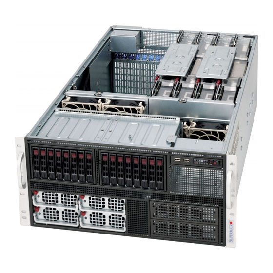
UPER ERVER 5086B-TRF User's Manual Figure 6-1. Front and Rear Chassis Views Front Chassis Features 1. Hot-swap Drive Bays 3. Power Supply Modules 2. Control Panel 4. Peripheral Drive Bays Rear Chassis Features 1. 9-cm Exhaust Fans 3. AC Power Sockets 2. -
Page 61: Installing The Baseboard Into The Chassis
Chapter 6: Advanced Chassis Setup Installing the Baseboard into the Chassis Refer to Chapter 5 for instructions on installing components such as CPUs and memory. Follow the instructions below to install the baseboard into the chassis. Tools Needed • Phillips Screwdriver •... -
Page 62: System Fans
Press the tab on the top of the fan housing of the failed fan and remove the entire housing unit. Replace the failed fan with an identical one (available from Supermicro). Posi- tion the new fan at its proper place in the chassis by fi tting the fan with its housing onto the fan mounts in the chassis. - Page 63 Chapter 6: Advanced Chassis Setup Figure 6-2. Replacing a Rear Exhaust Fan Figure 6-3. Replacing a System Fan...
-
Page 64: Drive Bay Installation/Removal
UPER ERVER 5086B-TRF User's Manual Drive Bay Installation/Removal Accessing the Drive Bays SATA Drives: You do not need to access the inside of the chassis or remove power to replace or swap SATA drives. Proceed to the next step for instructions. You must use 2.5"... - Page 65 Chapter 6: Advanced Chassis Setup Figure 6-4. Removing an HDD Carrier from the Chassis Enterprise level hard disk drives are recommended for use in Supermicro chassis and servers. For information on recommended HDDs, visit the Supermicro Web site at http://www.supermicro.com/products/nfo/fi les/ storage/SAS-CompList.pdf...
- Page 66 UPER ERVER 5086B-TRF User's Manual Figure 6-5. Removing the Dummy Drive from the Carrier Dummy Drive Drive Carrier Figure 6-6. Installing a Drive to a Carrier...
-
Page 67: Power Supply
The PWR Fail LED will illuminate and remain on until the failed unit has been replaced. Replacement units can be ordered directly from Supermicro. The power supply units have a hot-swap capability, meaning you can replace the failed unit without powering down the system. - Page 68 UPER ERVER 5086B-TRF User's Manual Figure 6-7. Installing a Power Supply Module 6-10...
-
Page 69: Chapter 7 Bios
When an option is selected in the left frame, it is highlighted in white. Often a text message will accompany it. Note: the AMI BIOS has default text messages built in. Supermicro retains the option to include, omit, or change any of these text messages. -
Page 70: Starting The Setup Utility
Warning! Do not upgrade the BIOS unless your system has a BIOS-related issue. Flashing the wrong BIOS can cause irreparable damage to the system. In no event shall Supermicro be liable for direct, indirect, special, incidental, or consequential damages arising from a BIOS update. If you have to update the BIOS, do not shut down or reset the system while the BIOS is updating. - Page 71 Chapter 7: BIOS • Build Date: This item displays the date when this BIOS was completed. Memory Information: The following memory information will be displayed: • Total Memory: This item displays the size of memory available in the system. System Language The feature allows the user to select a language setting for the Setup utility.
-
Page 72: Pci Subsystem Settings
UPER ERVER 5086B-TRF User's Manual Advanced Setup Confi guration Use the arrow keys to select the Advanced Setup menu and press <Enter> to ac- cess the submenu items. Legacy OpROM Support Use this feature to confi gure Option ROM settings which will allow the system to boot up via a legacy network device. - Page 73 Chapter 7: BIOS Above 4G Decoding Select Enabled to allow a 64_bit_capable device to be decoded in the address space above 4G if 64-bit_PCI_decoding is supported by the system. The options are Enabled and Disabled. PCI Common Settings PCI Latency Timer Select a value to be used by the PCI Latency Timer Register in bus clock calculation.
- Page 74 UPER ERVER 5086B-TRF User's Manual Maximum Payload Select Auto to allow the system BIOS to automatically set the maximum payload value for a PCI-E device to enhance system performance. The options are Auto, 128 Bytes, 256 Bytes, 512 Bytes, 1024 Bytes, 2048 Bytes, and 4096 Bytes. Maximum Read Request Select Auto to allow the system BIOS to automatically set the maximum Read Request size for a PCI-E device to enhance system performance.
-
Page 75: Trusted Computing
Chapter 7: BIOS Trusted Computing This feature allows the user to confi gure Trusting Computing settings. TPM Confi guration This future allows the user to set Trusted Platform Module Confi guration settings. TPM Support Select Enabled to enable TPM (Trusted Platform Module) support for system security and data integrity. - Page 76 UPER ERVER 5086B-TRF User's Manual WHEA Confi guration This feature allows the user to confi gure WHEA (Windows Hardware Error Archi- tecture) support settings. WHEA Support Select Enabled to enable WHEA support which will provide a common infrastruc- ture for the system to handle hardware errors on the Windows OS platforms in order to reduce system crashes due to hardware errors and to enhance system recovery and health monitoring.
- Page 77 Chapter 7: BIOS Clock Spread Spectrum Select Enable to enable Clock Spectrum support, which will allow the BIOS to moni- tor and attempt to reduce the level of Electromagnetic Interference caused by the components whenever needed. The options are Disabled and Enabled. Hyper-threading Select Enabled to use Hyper-Threading Technology, which will result in increased CPU performance.
-
Page 78: Runtime Error Logging
UPER ERVER 5086B-TRF User's Manual Power Technology Use this feature to select power management features for the system. Select Energy Effi cient to minimize power use. Select Custom to customize power use settings. The options are Disabled, Energy Effi cient and Custom. Intel®... - Page 79 Chapter 7: BIOS Memory Correctable Error Threshold This feature allows the user to enter the threshold value for memory correctable errors. The default setting is 10. SATA Confi guration When this submenu is selected, the AMI BIOS automatically detects the presence of the SATA devices and displays the following items: •...
- Page 80 UPER ERVER 5086B-TRF User's Manual USB Confi guration • USB Devices: This feature displays the status of the USB devices detected in the system. Legacy USB Support Select Enabled to support Legacy USB devices. If this item is set to Auto, the AMI BIOS will automatically enable Legacy USB support if a legacy USB device is de- tected.
- Page 81 Chapter 7: BIOS • The Default Alarm : Select this setting to trigger the CPU overheat alarm when the CPU temperature reaches about 5 C above the threshold temperature as predefi ned by the CPU manufacturer to give the CPU and system fans additional time needed for CPU and system cooling.
- Page 82 UPER ERVER 5086B-TRF User's Manual fans and CPU run normally as confi gured in the BIOS. User intervention: No action required. Medium – The processor is running warmer. This is a ‘precautionary’ level and generally means that there may be factors contributing to this condition, but the CPU is still within its normal operating state and the CPU ‘Tempera- ture Tolerance’...
-
Page 83: Serial Port Console Redirection
Chapter 7: BIOS Change Settings Use this feature to set the optimal Environment_Control_Interface (PECI) setting for a serial port specifi ed. The default setting is Auto, which will allow the AMI BIOS to automatically select the best setting for the PECI platform. Device Mode Use this feature to select the desired mode for a serial port specifi... - Page 84 UPER ERVER 5086B-TRF User's Manual Parity A parity bit can be sent along with regular data bits to detect data transmission errors. Select Even if the parity bit is set to 0, and the number of 1's in data bits is even.
-
Page 85: Network Stack
Chapter 7: BIOS Data Bits This feature allows the user to select data bits for console redirection transmis- sion. The options are 7 Bits and 8 Bits. Parity A parity bit can be sent with the data bits for data transmission errors. Select Even if the parity bit is set to 0 and the number of 1's in data bits is even. -
Page 86: Chipset
UPER ERVER 5086B-TRF User's Manual Chipset Use the arrow keys to select Chipset and press <Enter> to access the submenu items. This submenu allows the user to confi gure chipset settings. North Bridge This submenu allows the user to confi gure the following North Bridge parameters. Boxboro IOH Confi... - Page 87 Chapter 7: BIOS Coherency Support Select Enabled to enable Non-Isoch VT-d Engine Coherency support. The op- tions are Enabled and Disabled. ATS Support Select Enabled to enable VT-d Engine Address Translation Services support. The options are Enabled and Disabled. Pass-through DMA Select Enabled to enable Isoch/Non-Isoch VT-d Engine Pass-through DMA sup- port.
-
Page 88: Qpi Link
UPER ERVER 5086B-TRF User's Manual IOH Thermal Sensors This feature allows the user to confi gure integrated thermal sensor settings embed- ded in the 7500 chipset. Thermal Sensors Select Enabled to enable integrated thermal sensors embedded in the 7500 chipset. The options are Enabled and Disabled. •... - Page 89 Chapter 7: BIOS CSI (Common System Interface) Scrambling Select Enabled to support CSI data scrambling via 0:10h/11h:0:44h:22. The op- tions are Enabled and Disabled. Logical Interrupt Mode Use this feature to select the Logical Interrupt mode for the programmable inter- rupt controller (PIC) embedded in a multiple-processor system.
- Page 90 UPER ERVER 5086B-TRF User's Manual Memory Init mode Select Serial to set the memory initialization mode to Serial. Select Parallel to set the memory initialization mode to Parallel. The options are Serial and Parallel. Page Policy This feature allows the user to select the memory page policy for virtual memory support.
-
Page 91: South Bridge
Chapter 7: BIOS Patrol Scrub It is a memory error-correction scheme that works in the background looking for and correcting resident errors. The options are Enabled and Disabled. Patrol Scrub Interval Use this feature to set the hours needed for each Patrol Scrub cycle to complete the task. - Page 92 UPER ERVER 5086B-TRF User's Manual Restore on AC Power Loss Use this feature to set the power state after a power outage. Select Power-Off for the system power to remain off after a power outage. Select Power-On for the system power to be turned on after an outage. Select Last State to allow the system to resume its last state before a power loss.
-
Page 93: Server Management
Chapter 7: BIOS USB 2.0 (EHCI) Support Select Enabled for USB 2.0 EHCI (Extended Host Controller Interface) support. The options are Enabled and Disabled. EHCI Controller 1/2 Select Enabled to enable the EHCI controller specifi ed by the user to enhance USB communication. -
Page 94: System Event Log
UPER ERVER 5086B-TRF User's Manual FRB-2 Timer Timeout This feature allows the user to select the timeout value (between 3 minutes to 6 minutes) for an FRB-2 Timer, beyond which the activities in an FRB-2 timer will be terminated. The options are 3 Minutes, 4 Minutes, 5 Minutes, and 6 Minutes. FRB-2 Timer Policy This feature allows the user to decide how the system shall respond after an FRB-2 timeout. -
Page 95: Iscsi
Chapter 7: BIOS BMC Network Confi guration Use this feature to confi gure BMC (Baseboard Management Controller) Network settings. LAN Channel 1/ LAN Channel 2 Confi guration Source Use this feature to select the source or the parameter of an IP address for the LAN channel specifi... -
Page 96: Boot Confi Guration
UPER ERVER 5086B-TRF User's Manual Boot Confi guration This section allows the user to confi gure Boot settings. Quiet Boot This feature allows the user to select the bootup screen display between the POST messages and the OEM logo. Select Disabled to display the POST messages. Select Enabled to display the OEM logo instead of the normal POST messages. -
Page 97: Security
Chapter 7: BIOS Gate20 Active If Upon Request is selected, Gate20 can be disabled via BIOS. Select Always to keep Gate20 always active when executing any RT (Register Transfer) Code above 1 MB. The options are Always and Upon Request. Option ROM Message Use this feature to select the Option ROM mode setting. -
Page 98: Save & Exit
UPER ERVER 5086B-TRF User's Manual Administrator Password If "Administrator Password" is selected for the system, the user can use an admin- istrator password to enter the BIOS Setup Utility. No password will be needed for the user to enter the system at bootup. User Password If "User Password"... - Page 99 Chapter 7: BIOS Discard Changes and Reset Select this feature and press <Yes> in the dialog box to discard all the changes and reboot the system. Save Options Save Changes Select this feature and press <Yes> in the dialog box to save any changes you've made and reboot the system.
- Page 100 UPER ERVER 5086B-TRF User's Manual Notes 7-32...
-
Page 101: Appendix A Bios Error Beep Codes
Appendix A: BIOS POST Error Codes Appendix A BIOS Error Beep Codes During the POST (Power-On Self-Test) routines, which are performed each time the system is powered on, errors may occur. Non-fatal errors are those which, in most cases, allow the system to continue the bootup process. - Page 102 UPER ERVER 5086B-TRF User's Manual Notes...
-
Page 103: Appendix B System Specifi Cations
Appendix C: System Specifi cations Appendix B System Specifi cations Processors Eight Intel® Xeon 7500 Series 8-core processors and next generation Xeon E7 8800 family 10-core processors Note: Please refer to our web site for a complete listing of supported processors. Chipset Intel 7500 chipset (+ICH10R) BIOS... -
Page 104: System Cooling
UPER ERVER 5086B-TRF User's Manual System Cooling Six 9-cm hot-plug fans System Input Requirements AC Input Voltage: 180-240 VAC Rated Input Current: 7.2A (180V) to 9.5 (240V) Rated Input Frequency: 50-60 Hz Power Supply Rated Output Power: 1400W w/PFC (Part# PWS-1K41F-1R) Rated Output Voltages: +12V (117A), +5Vsb (6A) Operating Environment Operating Temperature: 10º... - Page 105 Appendix C: System Specifi cations Notes...
- Page 106 ERVER 5086B-TRF User's Manual (continued from front) The products sold by Supermicro are not intended for and will not be used in life support systems, medical equipment, nuclear facilities or systems, aircraft, aircraft devices, aircraft/emergency com- munication devices or other critical systems whose failure to perform be reasonably expected to result in signifi...
Need help?
Do you have a question about the Supero SUPERSERVER 5086B-TRF and is the answer not in the manual?
Questions and answers