Table of Contents
Advertisement
Quick Links
Advertisement
Table of Contents

Related Manuals for Supermicro SuperWorkstation 5049A-TR


Summary of Contents for Supermicro SuperWorkstation 5049A-TR
- Page 1 SuperWorkstation 5049A-TR USER’S MANUAL Revision 1.0...
- Page 2 State of California, USA. The State of California, County of Santa Clara shall be the exclusive venue for the resolution of any such disputes. Supermicro's total liability for all claims will not exceed the price paid for the hardware product.
- Page 3 If you have any questions, please contact our support team at: support@supermicro.com. This manual may be periodically updated without notice. Please check the Supermicro website for possible updates to the manual revision level. Warnings Special attention should be given to the following symbols used in this manual.
-
Page 4: Table Of Contents
SuperWorkstation 5049A-TR User's Manual Contents Chapter 1 Introduction 1.1 Overview ..........................9 1.2 Unpacking the System .......................10 1.3 System Features ........................11 1.4 Chassis Features .......................13 Control Panel ........................13 Front Features ........................15 Rear Features ........................16 1.5 Motherboard Layout ......................17 Quick Reference Table ......................18 Chapter 2 Installation 2.1 Overview ..........................21... - Page 5 Preface 2.6 Control Panel Orientation ....................31 2.7 Workstation Setup ......................33 Chapter 3 Maintenance and Component Installation 3.1 Removing Power ........................35 3.2 Accessing the System ......................35 3.3 Motherboard Components ....................39 Processor and Heatsink Installation ..................39 The Intel Xeon SP Series Processor ................39 Overview of the Processor Carrier Assembly ..............40 Overview of the CPU Socket ....................40 Overview of the Processor Heatsink Module ..............41...
- Page 6 SuperWorkstation 5049A-TR User's Manual 3.6 Chassis Components ......................57 Hard Drives ........................57 SATA Backplane ......................58 Installing Components in the 5.25" Drive Bays .............58 Removing the Empty Drive Bay ..................58 Adding a DVD-ROM Drive .....................58 System Cooling .........................59 System Fan Failure ......................59 Replacing System Fans ....................59...
- Page 7 Preface Appendix A BIOS Error Codes Appendix B Standardized Warning Statements for AC Systems Appendix C System Specifications Appendix D UEFI BIOS Recovery Appendix E BSMI RoHS...
- Page 8 SuperWorkstation 5049A-TR User's Manual Contacting Supermicro Headquarters Address: Super Micro Computer, Inc. 980 Rock Ave. San Jose, CA 95131 U.S.A. Tel: +1 (408) 503-8000 Fax: +1 (408) 503-8008 Email: marketing@supermicro.com (General Information) support@supermicro.com (Technical Support) Website: www.supermicro.com Europe Address: Super Micro Computer B.V.
-
Page 9: Chapter 1 Introduction
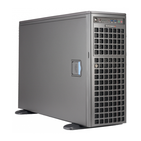
Chapter 1: Introduction Chapter 1 Introduction 1.1 Overview This chapter provides a brief outline of the functions and features of the 5049A-TR SuperWorkstation. The 5049A-TR is designed for applications such as data science, video rendering, and machine learning. The 5049A-TR is based on the X11SPA-T motherboard and the SC747BTS-R2K20BP chassis and can operate as a workstation or as a rackmounted system. -
Page 10: Unpacking The System
FAN-0148L4 MCP-320-00040-0N 1.2 Unpacking the System Inspect the box the SuperWorkstation 5049A-TR was shipped in and note if it was damaged in any way. If any equipment appears damaged, please file a damage claim with the carrier who delivered it. -
Page 11: System Features
Chapter 1: Introduction 1.3 System Features The following table provides you with an overview of the main features of the 5049A-TR. Please refer to Appendix C for additional specifications. System Features Motherboard X11SPA-T Chassis SC747BTS-R2K20BP Supports single 2 Gen/1 Gen Intel Xeon® Scalable-SP series and Intel Xeon® W-32XX series processors, up to 28 cores and 205W TDP Socket Type LGA3647... - Page 12 SuperWorkstation 5049A-TR User's Manual System Features Input/Output Front: Two USB3.2 Gen1x1 (5G), one power button, one system reset button, one audio port, two network activity LEDs, HDD LED, power status LED, system information LED Rear: Two USB3.2 Gen2x1 (10G) (one Type C and one Type A), four USB3.2 Gen1x1 (5G), three RJ45 LAN ports (GbE via Intel i210AT + AST2500 and 10GbE via AQC107), one VGA port via the BMC, one COM port, one HD audio 7.1 channel connector via Realtek ALC888S...
-
Page 13: Chassis Features
Chapter 1: Introduction 1.4 Chassis Features Control Panel The switches and LEDs located on the control panel are described below. See Chapter 4 for details on the control panel connections. Figure 1-1. Control Panel View... - Page 14 SuperWorkstation 5049A-TR User's Manual Control Panel Features Item Feature Description The main power switch is used to apply or remove power from the power supply to the server. Turning off system power with this button Power Button removes the main power but maintains standby power. To perform many maintenance tasks, you must unplug the system before servicing.
-
Page 15: Front Features
Chapter 1: Introduction Front Features The SC747BTS-R2K20BP is a 4U tower chassis that can also be rackmounted. See the illustration below for the features included on the front of the chassis. Figure 1-2. Chassis Front View Front Chassis Features Item Feature Description Control Panel... -
Page 16: Rear Features
SuperWorkstation 5049A-TR User's Manual Rear Features The illustration below shows the features included on the rear of the chassis. Figure 1-3. Chassis Rear View Rear Chassis Features Item Feature Description Power 1+1 2200W redundant power supply with PMBus Two 8-cm PWM hot-swap rear fans... -
Page 17: Motherboard Layout
Chapter 1: Introduction 1.5 Motherboard Layout Below is a layout of the X11SPA-T with jumper, connector, and LED locations shown. See the table on the following page for descriptions. For detailed descriptions, pinout information, and jumper settings, refer to Chapter 4. USB4/5 HD AUDIO AUDIO FP... -
Page 18: Quick Reference Table
SuperWorkstation 5049A-TR User's Manual Quick Reference Table Jumper Description Default Setting J9701, J9702 Manufacturing Mode Pins 1-2 (Normal) JPAC1 Audio Enable/Disable Pins 1-2 (Enabled) JPG1 VGA Enable/Disable Pins 1-2 (Enabled) JPL1, JPL2 LAN1/LAN2 Enable/Disable Pins 1-2 (Enabled) JPME2 Intel Manufacturing Mode... - Page 19 Chapter 1: Introduction Connector Description JOH1-OH Overheat LED Indicator JP4, JP5 JP4: Enable/Disable USB10/11, JP5: Enable/Disable USB8/9 JPI2C1 Power Supply SMBus I2C Header JPUSB1 Enable/Disable USB6/7 WakeUp JPWR1/3/4 +12V 8-pin CPU Power Connectors (required) JPWR2 24-pin ATX Main Power Connector (required) Intel RAID Key Header JRK1 Note: A VROC hardware key is required to enable an M.2 RAID card.
- Page 20 SuperWorkstation 5049A-TR User's Manual VR13 VCCP0 12V 6+1+1 PHASE VPP (2.625) 5v 4 x M.2 SOCKET SSD 205W VDDQ (1.2) 12v DDR4 (CHA) VTT_M (0.6) DIMMA1 x4 x4 x4 x4 2133/2666 (2933) MHz DIMMA2 PCI-E x16 G3 IT8898*8 DDR4 (CHB)
-
Page 21: Chapter 2 Installation
Chapter 2: Installation Chapter 2 Installation 2.1 Overview This chapter provides advice and instructions for rack or workstation installation. The system is shipped in a workstation configuration. Follow the steps in this chapter to prepare the chassis for rackmounting or for returning the chassis into a workstation configuration. If your system is not already fully integrated with processors, system memory etc., refer to Chapter 3 for details on installing those specific components. -
Page 22: Choosing A Setup Location
SuperWorkstation 5049A-TR User's Manual Choosing a Setup Location • The system should be situated in a clean, dust-free area that is well ventilated. Avoid areas where heat, electrical noise and electromagnetic fields are generated. • Leave enough clearance in front of the rack so that you can open the front door completely (~25 inches) and approximately 30 inches of clearance in the back of the rack to allow sufficient space for airflow and access when servicing. -
Page 23: Airflow
Chapter 2: Installation Airflow Equipment should be mounted into a rack so that the amount of airflow required for safe operation is not compromised. Mechanical Loading Equipment should be mounted into a rack so that a hazardous condition does not arise due to uneven mechanical loading. -
Page 24: Preparing The Chassis For Rack Mounting
SuperWorkstation 5049A-TR User's Manual 2.3 Preparing the Chassis for Rack Mounting The chassis top tower cover and feet must be removed before rack installation. Removing the Top Tower Cover 1. Locate the blue cover lock at the rear of the cover. -
Page 25: Installing The Rails
Chapter 2: Installation 2.4 Installing the Rails This section provides a guideline for installing the rails to the chassis and to the rack with the optional rack mount kit. Identifying the Sections of the Rack Rails The chassis package includes two optional rack rail assemblies in the rack mounting kit. Each assembly consists of two sections: An inner fixed chassis rail that secures directly to the server chassis and an outer fixed rack rail that secures directly to the rack itself. -
Page 26: Installing The Inner Rails To The Chassis
SuperWorkstation 5049A-TR User's Manual Installing the Inner Rails to the Chassis 1. Attach the handles to the front of the chassis with three screws each. 2. Identify the left and right inner rails. They are labeled on the rails and in the figure below. -
Page 27: Installing The Outer Rails To The Rack
Chapter 2: Installation Installing the Outer Rails to the Rack Installing the Outer Rails 1. Attach the rear rail to the middle rail. 2. Adjust both to the proper distance so that the rails fit snugly into the rack. 3. Secure the rear rail with two M5 screws at the rear of the rack. 4. -
Page 28: Installing The Chassis Into The Rack
SuperWorkstation 5049A-TR User's Manual 2.5 Installing the Chassis into the Rack With rails attached to both the chassis and the rack, install the system into the rack. 1. Confirm that the chassis includes the inner rails and the outer rails. - Page 29 Chapter 2: Installation Warning: Stability hazard. The rack stabilizing mechanism must be in place, or the rack must be bolted to the floor before you slide the unit out for servicing. Failure to stabilize the rack can cause the rack to tip over. When initially installing the system to a rack, test that the rail locking tabs engage to prevent the system from being overextended.
-
Page 30: Removing The Chassis From The Rack
SuperWorkstation 5049A-TR User's Manual Removing the Chassis from the Rack Caution! It is dangerous for a single person to off-load the heavy chassis from the rack without assistance. Be sure to have sufficient assistance supporting the chassis when removing it from the rack. -
Page 31: Control Panel Orientation
Chapter 2: Installation 2.6 Control Panel Orientation The server can be configured for either tower or server rack orientation. It is shipped in tower mode and can be immediately used as a desktop server. To use it in a rack, rotate the module that contains the control panel and the three drive trays ( in Figure 2-7) 90 degrees. - Page 32 SuperWorkstation 5049A-TR User's Manual Rotating the Control Panel/Drive Module for Rack Mounting 1. Power down the system as described in Section 3.1 and open the side cover as described in Section 3.2. 2. Disconnect any cables from the back of the Control Panel/Drive Module.
-
Page 33: Workstation Setup
Chapter 2: Installation 2.7 Workstation Setup The system can be configured in a workstation or a server rack orientation. It is shipped as a workstation with the chassis cover and feet pre-installed. Use the instructions below to convert a rackmounted system to tower mode. Returning a Rackmounted System to a Workstation Setup 1. - Page 34 SuperWorkstation 5049A-TR User's Manual 6. Place the chassis foot in the foot receptacle and slide the foot toward the front of the chassis. The foot should lock into place. 7. Secure the foot to the chassis using two screws enclosed in the packaging.
-
Page 35: Chapter 3 Maintenance And Component Installation
Chapter 3: Maintenance and Component Installation Chapter 3 Maintenance and Component Installation This chapter provides instructions on installing and replacing main system components. To prevent compatibility issues, only use components that match the specifications and/or part numbers given. Installation or replacement of most components require that power first be removed from the system. - Page 36 SuperWorkstation 5049A-TR User's Manual Top Cover Side Cover Front Cover Figure 3-1. Identifying the Chassis Covers Caution: Except for short periods of time, do not operate the server without the cover in place. The chassis cover must be in place to allow for proper airflow and to prevent overheating.
- Page 37 Chapter 3: Maintenance and Component Installation Removing the Side Cover 1. Remove power from the system as described in Section 3.1. 2. Lift the handle at the side of the tower. 3. Lift the cover from the chassis. Lift Up the Handle Lift Up the Side Cover Figure 3-2.
- Page 38 SuperWorkstation 5049A-TR User's Manual Opening the Front Cover The front cover houses up to eight hot-swappable hard drives. The cover can be locked to prevent unauthorized access. The key to this lock is shipped with the system. 1. Unlock the front cover using the key shipped with the system.
-
Page 39: Motherboard Components
Check that the plastic socket dust cover is in place and none of the socket pins are bent— otherwise, contact your retailer. • Refer to the Supermicro website for updates on CPU support. • Graphics in this manual are for illustration. Your components may look slightly different. -
Page 40: Overview Of The Processor Carrier Assembly
SuperWorkstation 5049A-TR User's Manual Overview of the Processor Carrier Assembly The processor carrier assembly contains the Intel Xeon Non-Fabric (Non-F) processor and a processor carrier. Non-F Processor Processor Carrier Overview of the CPU Socket The CPU socket is protected by a plastic protective cover. -
Page 41: Overview Of The Processor Heatsink Module
Chapter 3: Maintenance and Component Installation Overview of the Processor Heatsink Module The Processor Heatsink Module (PHM) contains a heatsink, a processor carrier, and the Intel Xeon Non-Fabric (Non-F) processor. Heatsink with Thermal Grease Processor Carrier Non-F Processor... -
Page 42: Creating The Non-F Model Processor Carrier Assembly
SuperWorkstation 5049A-TR User's Manual Creating the Non-F Model Processor Carrier Assembly To install a Non-F model processor into the processor carrier, follow the steps below. 1. Hold the processor with the LGA lands (gold contacts) facing up. Locate the small, gold triangle in the corner of the processor and the corresponding hollowed triangle on the processor carrier. -
Page 43: Attaching The Non-F Model Processor Package Assembly To The Heatsink To Form The Processor Heatsink Module (Phm)
Chapter 3: Maintenance and Component Installation Attaching the Non-F Model Processor Package Assembly to the Heatsink to Form the Processor Heatsink Module (PHM) After you have made a processor package assembly by following the instructions on the previous page, please follow the steps below to mount the processor package assembly onto the heatsink to create the Processor Heatsink Module (PHM). -
Page 44: Preparing The Cpu Socket For Installation
SuperWorkstation 5049A-TR User's Manual Preparing the CPU Socket for Installation This motherboard comes with a plastic protective cover installed on the CPU socket. Remove it from the socket to install the Processor Heatsink Module (PHM). Gently pull up one corner of the plastic protective cover to remove it. -
Page 45: Installing The Processor Heatsink Module (Phm)
Chapter 3: Maintenance and Component Installation Installing the Processor Heatsink Module (PHM) 1. Once you have assembled the processor heatsink module (PHM) by following the instructions listed on page 42, you are ready to install the processor heatsink module (PHM) into the CPU socket on the motherboard. To install the PHM into the CPU socket, follow the instructions below. -
Page 46: Removing The Processor Heatsink Module (Phm) From The Motherboard
SuperWorkstation 5049A-TR User's Manual Removing the Processor Heatsink Module (PHM) from the Motherboard Before removing the processor heatsink module (PHM), unplug the power cord from the power outlet. 1. Using a T30 Torx-bit screwdriver, turn the screws on the PHM counterclockwise to loosen them from the socket, starting with the screw marked #4 (in the sequence of 4, 3, 2, 1). -
Page 47: Memory Support And Installation
Chapter 3: Maintenance and Component Installation 3.4 Memory Support and Installation The X11SPA-T supports up to 768GB of ECC RDIMM, 3TB of 3DS RDIMM, 1.5TB of LRDIMM, and 3TB of 3DS LRDIMM DDR4 (288-pin) ECC memory with speeds of up to 2933MHz in 12 memory slots. -
Page 48: Ddr4 Memory Support For The 81Xx/61Xx/51Xx/41Xx/31Xx Platform
SuperWorkstation 5049A-TR User's Manual DDR4 Memory Support for the 81xx/61xx/51xx/41xx/31xx Platform DDR4 Memory Support Speed (MT/s); Voltage (V); Slots Per Channel (SPC) and DIMMs Per Channel (DPC) DIMM Capacity (GB) Ranks 1 Slot Per 2 Slots Per Channel Channel Type... -
Page 49: Dimm Population Guidelines For Optimal Performance
Chapter 3: Maintenance and Component Installation DIMM Population Guidelines for Optimal Performance For optimal memory performance, follow the instructions listed in the tables below when populating memory modules. Key Parameters for DIMM Configuration Key Parameters for DIMM Configurations Parameters Possible Values Number of Channels 1, 2, 3, 4, 5, or 6 Number of DIMMs per Channel... -
Page 50: Memory Population
SuperWorkstation 5049A-TR User's Manual Memory Population Memory Population Table for the X11SPA-T (with 12 Slots) based on the 81xx/61xx/51xx/41xx/31xx and 82xx/62xx/52xx/42xx/32xx and W-32XX series Platforms. Memory Population Table for the X11SPA-T (with 12 Slots) Memory Population Sequence 1 CPU & 1 DIMM CPU1: P1-DIMMA1 1 CPU &... -
Page 51: General Guidelines For Optimizing Memory Performance
Chapter 3: Maintenance and Component Installation General Guidelines for Optimizing Memory Performance • The blue slots must be populated first. • Only populate DIMMA2 and DIMMD2 if the extra memory support is needed. • Always use DDR4 memory of the same type, size, and speed. •... -
Page 52: Dimm Installation
SuperWorkstation 5049A-TR User's Manual DIMM Installation Universal ID UID-LED UID-SW 1. Insert the desired number of DIMMs JPAC1 JSPDIF_OUT AUDIO FP ASPEED HD AUDIO JPUSB1 AST2500 COM1 JPWR4 USB8/9 (3.1) USB4/5(3.0) USB6/7 (3.0) USB3.1 Gen.2 USB3.1 Gen.1 USB3.1 Gen.1 LAN1... -
Page 53: Motherboard Battery
Chapter 3: Maintenance and Component Installation Motherboard Battery The motherboard uses non-volatile memory to retain system information when system power is removed. This memory is powered by a lithium battery residing on the motherboard. Replacing the Battery 1. Remove power from the system as described in Section 3.1 and remove the node from the chassis. -
Page 54: Ssd Installation
SuperWorkstation 5049A-TR User's Manual 3.5 M.2 SSD Installation The X11SPA-T motherboard has four M.2 PCI-E 3.0 slots that support 2260, 2280, and 22110 SSD modules. 1. Loosen the screws and remove the heatsink. 2. The default positions for the 3. The mounting screws on the... -
Page 55: 2280 Ssd Module Installation
Chapter 3: Maintenance and Component Installation 2280 SSD Module Installation 2280 2280 4.2. With the cutoff circle at the end of the 4.1. To install a 2280 SSD module, insert it into the slot at a 30 degree module aligned with the standoff, tighten angle and press down. -
Page 56: 22110 Ssd Module Installation
SuperWorkstation 5049A-TR User's Manual 22110 SSD Module Installation 22110 22110 4.5. To install a 22110 SSD module, 4.6. Go to step 5 to complete the insert it into the M.2 slot at a 30 degree installation. angle and align the cutoff circle at the end with the standoff. -
Page 57: Chassis Components
Chapter 3: Maintenance and Component Installation 3.6 Chassis Components Hard Drives A total of eight SATA drives may be housed in the SC747BTS-R2K20BP chassis. The drive IDs are preconfigured as 0 through 7 in order from bottom to top (or from left to right if rackmounted). -
Page 58: Sata Backplane
SuperWorkstation 5049A-TR User's Manual Figure 3-6. Mounting a Drive in a Carrier Note: Enterprise level hard disk drives are recommended for use in Supermicro chassis and servers. For information on recommended HDDs, visit the Supermicro website at http://www. supermicro.com/products/nfo/storage.cfm SATA Backplane The SATA drives plug into a drive backplane. -
Page 59: System Cooling
Chapter 3: Maintenance and Component Installation System Cooling Heavy-duty fans provide cooling for the chassis. Four fans are located in the mid-section of the chassis, two fans are located in the rear, and two optional fans can be mounted on the external rear of the chassis, required for passive GPUs. - Page 60 SuperWorkstation 5049A-TR User's Manual FAN-0114L4 Mid-Fan Release Tab FAN-0138L4 Figure 3-7. Mid-System Chassis Fans FAN-0082L4 Rear Fan Release Tab Figure 3-8. Rear System Chassis Fans...
-
Page 61: Power Supply
Chapter 3: Maintenance and Component Installation Power Supply The SuperWorkstation 5049A-TR includes two 1+1 2200W redundant power supplies. These power supplies are auto-switching capable. This enables it to automatically sense and operate at a 100V to 240V input voltage. An amber light will be illuminated on the power supply when the power is off. -
Page 62: Chapter 4 Motherboard Connections
SuperWorkstation 5049A-TR User's Manual Chapter 4 Motherboard Connections This section describes the connections on the motherboard and provides pinout definitions. Note that depending on how the system is configured, not all connections are required. The LEDs on the motherboard are also described here. The motherboard layout indicating component locations may be found in Chapter 1. -
Page 63: Headers And Connectors
Chapter 4: Motherboard Connections 8-Pin Power Connectors JPWR1/JPWR3/JPWR4 are 8-pin 12V DC power inputs for the CPU on the X11SPA-T motherboard. Besides the 24-pin ATX PWR (JPWR2), two 12V 8-pin power connections (JPWR1/JPWR3) are required to ensure adequate power supply to the system. Refer to the table below for pin definitions. - Page 64 SuperWorkstation 5049A-TR User's Manual SGPIO Headers There are two Serial Link General Purpose Input/Output (I-SGPIO1 and I-SGPIO2) headers located on the motherboard. Refer to the tables below for pin definitions. I-SGPIO Header Pin Definitions Pin# Definition Pin# Definition Ground Data...
- Page 65 Chapter 4: Motherboard Connections Standby Power Header The Standby Power header is located at JSTBY1 on the motherboard. You must have a card with a Standby Power connector and a cable to use this feature. Refer to the table below for pin definitions.
- Page 66 SuperWorkstation 5049A-TR User's Manual Power LED/Speaker Connector Pins 1-3 of JD1 are used for power LED indication, and pins 4-7 are for the speaker. Please note that the speaker connector pins (4-7) are used with an external speaker. If you wish to use the onboard speaker, you should close pins 6-7 with a cap.
- Page 67 Chapter 4: Motherboard Connections Chassis Intrusion Header A Chassis Intrusion header is located at JL1 on the motherboard. Attach the appropriate cable from the chassis to inform you of a chassis intrusion when the chassis is opened. Refer to the table below for pin definitions. Chassis Intrusion Header Pin Definitions Pin#...
-
Page 68: Rear I/O Ports
SuperWorkstation 5049A-TR User's Manual 4.3 Rear I/O Ports Figure 4-1. Rear I/O Ports Rear I/O Ports Item Description Item Description Item Description 1Gb RJ45 Port 1 USB 3.2 Gen1 (5G) Surround Out USB 3.2 Gen2x1 (10G) USB 3.2 Gen1 (5G) S/PDIF Out USB 3.2 Gen2x1 (10G) - Page 69 Chapter 4: Motherboard Connections VGA Port A video (VGA) port is located next to USB 3.2 Gen2x1 Port 8 (Type C) on the I/O back panel. COM Connections Two COM connections (COM1/COM2) are located on the motherboard. COM1 is located on the I/O back panel.
- Page 70 SuperWorkstation 5049A-TR User's Manual Universal Serial Bus (USB) Ports There are four USB 3.2 Gen1 ports (USB4/5, USB6/7) and two USB 3.2 Gen2x1 ports (USB8/9) located on the I/O back panel. The motherboard also has two front access USB 3.2 Gen2x1 headers (USB10, USB11), one front access USB 2.0 header (USB0/1), and one front access USB 3.2 Gen1 header (USB2/3).
- Page 71 Note: UID can also be triggered via IPMI on the motherboard. For more information on IPMI, please refer to the IPMI User's Guide posted on our website at http://www.supermicro.com/ products/nfo/IPMI.cfm. UID Switch...
-
Page 72: Front Control Panel
SuperWorkstation 5049A-TR User's Manual 4.4 Front Control Panel JF1 contains header pins for various buttons and indicators that are normally located on a control panel at the front of the chassis. These connectors are designed specifically for use with a Supermicro chassis. - Page 73 Chapter 4: Motherboard Connections Power Fail LED The Power Fail LED connection is located on pins 5 and 6 of JF1. Refer to the table below for pin definitions. Power Fail LED Pin Definitions (JF1) Pins Definition 3.3V PWR Supply Fail Overheat (OH)/Fan Fail LED Connect an LED cable to pins 7 and 8 of the Front Control Panel to use the Overheat/Fan Fail LED connections.
- Page 74 SuperWorkstation 5049A-TR User's Manual HDD LED The HDD LED connection is located on pins 13 and 14 of JF1. Attach a cable to pin 14 to show hard drive activity status. Refer to the table below for pin definitions. HDD LED...
-
Page 75: Jumpers
Chapter 4: Motherboard Connections 4.5 Jumpers Explanation of Jumpers To modify the operation of the motherboard, jumpers are used to choose between optional settings. Jumpers create shorts between two pins to change the function associated with it. Pin 1 is identified with a square solder pad on the printed circuit board. See the motherboard layout page for jumper locations. - Page 76 SuperWorkstation 5049A-TR User's Manual Watchdog Watchdog (JWD1) is a system monitor that can reboot the system when a software application hangs. Close pins 1-2 to reset the system if an application hangs. Close pins 2-3 to generate a non-maskable interrupt (NMI) signal for the application that hangs. Refer to the table below for jumper settings.
- Page 77 Chapter 4: Motherboard Connections 1Gb/10Gb LAN Enable/Disable JPL1 and JPL2 allows the user to enable or disable the 1Gb/10Gb LAN Ports. The default setting is Enabled. 1Gb/10Gb LAN Enable/Disable Jumper Settings Jumper Setting Definition Pins 1-2 Enabled (Default) Pins 2-3 Disabled USB Wake-Up This jumper allows you to "wake up"...
-
Page 78: Led Indicators
SuperWorkstation 5049A-TR User's Manual 4.6 LED Indicators Rear Unit ID LED A rear UID LED indicator (UID-LED) is located near the UID switch on the I/O back panel. This UID indicator provides easy identification of a system unit that may need service. - Page 79 Chapter 4: Motherboard Connections M.2 LED The M.2 LED is located at LE3, LE4, LE5, and LE6 on the motherboard. When the M.2 LED is blinking, its corresponding M.2 device functions normally. Refer to the table below for more information. LED Settings LED Color Definition...
-
Page 80: Chapter 5 Software
USB/SATA DVD drive, or a USB flash drive, or the IPMI KVM console. 2. Retrieve the proper RST/RSTe driver. Go to the Supermicro web page for your motherboard and click on "Download the Latest Drivers and Utilities", select the proper driver, and copy it to a USB flash drive. - Page 81 Chapter 5: Software 4. During Windows Setup, continue to the dialog where you select the drives on which to install Windows. If the disk you want to use is not listed, click on “Load driver” link at the bottom left corner. Figure 5-2.
-
Page 82: Driver Installation
The Supermicro website contains drivers and utilities for your system at https://www. supermicro.com/wftp/driver. Some of these must be installed, such as the chipset driver. After accessing the website, go into the CDR_Images (in the parent directory of the above link) and locate the ISO file for your motherboard. Download this file to to a USB flash drive or a DVD. -
Page 83: Superdoctor ® 5
5.3 SuperDoctor ® The Supermicro SuperDoctor 5 is a program that functions in a command-line or web-based interface for Windows and Linux operating systems. The program monitors such system health information as CPU temperature, system voltages, system power consumption, fan speed, and provides alerts via email or Simple Network Management Protocol (SNMP). -
Page 84: Ipmi
The X11SPA-T supports the Intelligent Platform Management Interface (IPMI). IPMI is used to provide remote access, monitoring and management. There are several BIOS settings that are related to IPMI. For general documentation and information on IPMI, please visit our website at: http://www.supermicro.com/products/nfo/IPMI.cfm. -
Page 85: Chapter 6 Uefi Bios
Chapter 6: UEFI BIOS Chapter 6 UEFI BIOS 6.1 Introduction This chapter describes the AMIBIOS™ Setup utility for the X11SPA-T motherboard. The is stored on a chip and can be easily upgraded using a flash program. Note: Due to periodic changes to the BIOS, some settings may have been added or deleted and might not yet be recorded in this manual. -
Page 86: Main Setup
SuperWorkstation 5049A-TR User's Manual 6.2 Main Setup When you first enter the AMI BIOS setup utility, you will enter the Main setup screen. You can always return to the Main setup screen by selecting the Main tab on the top of the screen. - Page 87 Chapter 6: UEFI BIOS CPLD Version This feature displays the Complex Programmable Logic Device version. Memory Information Total Memory This feature displays the total size of memory available in the system.
-
Page 88: Advanced Setup Configurations
SuperWorkstation 5049A-TR User's Manual 6.3 Advanced Setup Configurations Use the arrow keys to select the Advanced menu and press <Enter> to access the submenu items: Warning: Take caution when changing the Advanced settings. An incorrect value, a very high DRAM frequency, or an incorrect DRAM timing setting may make the system unstable. When this occurs, revert to default manufacturer settings. - Page 89 Chapter 6: UEFI BIOS Wait For "F1" If Error Use this feature to force the system to wait until the "F1" key is pressed if an error occurs. The options are Disabled and Enabled. INT19 (Interrupt 19) Trap Response Interrupt 19 is the software interrupt that handles the boot disk function. When this feature is set to Immediate, the ROM BIOS of the host adapters will "capture"...
- Page 90 SuperWorkstation 5049A-TR User's Manual CPU Configuration The following CPU information will display: • Processor BSP Revision • Processor Socket • Processor ID • Processor Frequency • Processor Max Ratio • Processor Min Ratio • Microcode Revision • L1 Cache RAM •...
- Page 91 Chapter 6: UEFI BIOS Intel Virtualization Technology Use this feature to enable the Vanderpool Technology. This technology allows the system to run several operating systems simultaneously. The options are Disable and Enable. PPIN Control Select Unlock/Enable to use the Protected Processor Inventory Number (PPIN) in the system. The options are Unlock/Disable and Unlock/Enable.
- Page 92 SuperWorkstation 5049A-TR User's Manual Advanced Power Management Configuration Power Technology Select Energy Efficient to support power-saving mode. Select Custom to customize system power settings. Select Disabled to disable power-saving settings. The options are Disable, Energy Efficient, and Custom. *If the feature is set to Custom, the following features will display: Power Performance Tuning (Available when "Power Technology"...
- Page 93 Chapter 6: UEFI BIOS Turbo Mode This feature will enable dynamic control of the processor, allowing it to run above stock frequency. The options are Disable and Enable. Hardware PM State Control Hardware P-States This feature allows the user to select between OS and hardware-controlled P-states. Selecting Native Mode allows the OS to choose a P-state.
- Page 94 SuperWorkstation 5049A-TR User's Manual CPU T State Control Software Controlled T-States Use this feature to enable Software Controlled T-States. The options are Disable and Enable. Chipset Configuration Warning: Setting the wrong values in the following features may cause the system to malfunction.
- Page 95 Chapter 6: UEFI BIOS IO Directory Cache (IODC) IO Directory Cache is an 8-entry cache that stores the directory state of remote IIO writes and memory lookups, and saves directory updates. Use this feature to lower cache to cache (C2C) transfer latencies. The options are Disable, Auto, Enable for Remote InvItoM Hybrid Push, InvItoM AllocFlow, Enable for Remote InvItoM Hybrid AllocNonAlloc, and Enable for Remote InvItoM and Remote WCiLF.
- Page 96 SuperWorkstation 5049A-TR User's Manual Memory Configuration Enforce POR Select POR (Plan of Record) to enforce POR restrictions on DDR4 frequency and volt- age programming. The options are POR and Disable. PPR Type Use this feature to select Post Package Repair Type. The options are Auto, Hard PPR, Soft PPR, and PPR Disabled.
- Page 97 Chapter 6: UEFI BIOS Memory Topology This feature displays the information of onboard memory modules as detected by the BIOS. Memory RAS Configuration Static Virtual Lockstep Mode Select Enable to run the system's memory channels in lockstep mode to minimize memory access latency.
- Page 98 SuperWorkstation 5049A-TR User's Manual Patrol Scrub Patrol Scrubbing is a process that allows the CPU to correct correctable memory errors detected on a memory module and send the correction to the requestor (the original source). When this feature is set to Enable, the IO hub will read and write back one cache line every 16K cycles if there is no delay caused by internal processing.
- Page 99 Chapter 6: UEFI BIOS PCI-E Port Max Payload Size Selecting Auto for this feature will enable the motherboard to automatically detect the maximum Transaction Layer Packet (TLP) size for the connected PCI-E device, allowing for maximum I/O efficiency. Selecting 128B or 256B will designate maximum packet size of 128 or 256.
- Page 100 SuperWorkstation 5049A-TR User's Manual PassThrough DMA Use this feature to allow devices such as network cards to access the system memory without using a processor. Select Enable to use the Non-Isoch VT-d Engine Pass Through Direct Memory Access (DMA) support. The options are Enable and Disable.
- Page 101 Chapter 6: UEFI BIOS VMD Config for PStack1 Intel VMD for Volume Management Device Select Enable to use the Intel Volume Management Device Technology for this stack. The options are Disable and Enable. *If the feature above is set to Enable, the following features will become avail- able for configuration: CPU SLOT7 PCI-E 3.0 x16 VMD/CPU SLOT6 PCI-E 3.0 x8 VMD (Available when the device is detected by the system)
- Page 102 SuperWorkstation 5049A-TR User's Manual South Bridge The following USB information will display: • USB Module Version • USB Devices Legacy USB Support This feature enables support for USB 2.0 and older. The options are Enabled, Disabled, and Auto. XHCI Hand-off When this feature is disabled, the motherboard will not support USB 3.0.
- Page 103 Chapter 6: UEFI BIOS • Recovery Firmware Version • ME Firmware Status #1 • ME Firmware Status #2 • Current State • Error Code PCH SATA Configuration When this submenu is selected, the AMI BIOS automatically detects the presence of the SATA devices that are supported by the Intel PCH chip and displays the following features: SATA Controller This feature enables or disables the onboard SATA controller supported by the Intel PCH...
- Page 104 SuperWorkstation 5049A-TR User's Manual Port 0 ~ Port 7 Hot Plug Set this feature to Enable for hot plug support, which will allow the user to replace a SATA drive without shutting down the system. The options are Disable and Enable.
- Page 105 Chapter 6: UEFI BIOS NVMe Firmware Source Use this feature to select the NVMe firmware to support booting. The options are Vendor Defined Firmware and AMI Native Support. The default option, Vendor Defined Firmware, is pre-installed on the drive and may resolve errata or enable innovative functions for the drive.
- Page 106 SuperWorkstation 5049A-TR User's Manual Use this feature to select which firmware type to be loaded for the add-on card in this slot. The options are Disabled, Legacy, and EFI. M.2C03 PCI-E 3.0 x4 OPROM Use this feature to select which firmware type to be loaded for the add-on card in this slot.
- Page 107 Chapter 6: UEFI BIOS IPv4 HTTP Support Select Enabled to enable IPv4 HTTP boot support. The options are Disabled and Enabled. IPv6 PXE Support Select Enabled to enable IPv6 PXE boot support. The options are Disabled and Enabled. IPv6 HTTP Support Select Enabled to enable IPv6 HTTP boot support.
- Page 108 SuperWorkstation 5049A-TR User's Manual Serial Port 2 Configuration This submenu allows the user to configure the settings of Serial Port 2. Serial Port 2 Select Enabled to enable the selected onboard serial port. The options are Disabled and Enabled. Device Settings This feature displays the status of a serial part specified by the user.
- Page 109 Chapter 6: UEFI BIOS lower transmission speed may be required for long and busy lines. The options are 9600, 19200, 38400, 57600, and 115200 (bits per second). COM1 Data Bits Use this feature to set the data transmission size for Console Redirection. The options are 7 Bits and 8 Bits.
- Page 110 SuperWorkstation 5049A-TR User's Manual This feature selects the settings for Function Keys and KeyPad used for Putty, which is a terminal emulator designed for the Windows OS. The options are VT100, LINUX, XTERMR6, SC0, ESCN, and VT400. COM1 Redirection After BIOS POST Use this feature to enable or disable legacy console redirection after BIOS POST.
- Page 111 Chapter 6: UEFI BIOS Odd if the parity bit is set to 0, and the number of 1's in data bits is odd. Select None if you do not want to send a parity bit with your data bits in transmission. Select Mark to add a mark as a parity bit to be sent along with the data bits.
- Page 112 SuperWorkstation 5049A-TR User's Manual Legacy Serial Redirection Port Use this feature to select a COM port to display redirection of Legacy OS and Legacy OPROM messages. The options are COM1 and SOL/COM2. EMS (Emergency Management Services) Console Redirection Select Enabled to use a COM port selected by the user for EMS Console Redirection. The options are Enabled and Disabled.
- Page 113 Chapter 6: UEFI BIOS ACPI Settings WHEA Support Select Enabled to support the Windows Hardware Error Architecture (WHEA) platform and provide a common infrastructure for the system to handle hardware errors within the Windows OS environment to reduce system crashes and to enhance system recovery and health monitoring.
- Page 114 SuperWorkstation 5049A-TR User's Manual Use this feature to disable or enable the SHA256 Platform Configuration Register (PCR) bank for the installed TPM device. The options are Disabled and Enabled. Pending Operation Use this feature to schedule a TPM-related operation to be performed by a security device for system data integrity.
- Page 115 Chapter 6: UEFI BIOS TLS Authenticate Configuration Server CA Configuration Enroll Certification Enroll Cert Using File Cert GUID Commit Changes and Exit Discard Changes and Exit Delete Certification Change Attempt order Intel® Virtual RAID on CPU This submenu displays the information of the Intel VMD controllers as detected by the BIOS. Intel®...
- Page 116 SuperWorkstation 5049A-TR User's Manual Detected DIMMs: This feature displays the number of DIMMs as detected by the system. All DIMMs are healthy. DIMMs This feature configures and displays the information of a selected DCPMM. Select a specific DIMM to view more information.
- Page 117 Chapter 6: UEFI BIOS Serial number 0x0000115D Part number NMA1XBD256GQS Socket Memory controller ID Vendor ID 0x8089 Device ID 0x5141 Subsystem vendor ID 0x8089 Subsystem device ID 0x97A Device locator P1-DIMMA2 Subsystem revision ID 0x18 Interface format code 0x0301 (Non-Energy Backed Byte Addressable) Manufacturing info valid Manufacturing date 18-37...
- Page 118 SuperWorkstation 5049A-TR User's Manual App Direct capacity Unconfigured capacity Inaccessible capacity Reserved capacity 465.2 MiB Peak power budget [mW] 20000 Avg power budget [mW] 15000 Max average power budget [mW] 10000 Package sparing capable 1 Package sparing enabled 1 Package spares available 1...
- Page 119 Chapter 6: UEFI BIOS Software triggers enabled [0] Software triggers enabled details None Poison error injection counter 0 Poison error clear counter 0 Media temperature injection counter 0 Software triggers counter 0 Master Passphrase Enabled 0 DIMM ID 0x0101 Press <Enter> and the following information regarding this DIMM will be displayed. View settings or select an action below.
- Page 120 SuperWorkstation 5049A-TR User's Manual Serial number 0x00000B35 Part number NMA1XBD256GQS Socket Memory controller ID Vendor ID 0x8089 Device ID 0x5141 Subsystem vendor ID 0x8089 Subsystem device ID 0x97A Device locator P1-DIMMD2 Subsystem revision ID 0x18 Interface format code 0x0301 (Non-Energy Backed Byte Addressable)
- Page 121 Chapter 6: UEFI BIOS App Direct capacity Unconfigured capacity Inaccessible capacity Reserved capacity 465.2 MiB Peak power budget [mW] 20000 Avg power budget [mW] 15000 Max average power budget [mW] 10000 Package sparing capable 1 Package sparing enabled 1 Package spares available 1 Configuration status [Valid] SKU violation...
- Page 122 SuperWorkstation 5049A-TR User's Manual Media temperature injection enabled [0] Software triggers enabled [0] Software triggers enabled details None Poison error injection counter 0 Poison error clear counter 0 Media temperature injection counter 0 Software triggers counter 0 Master Passphrase Enabled 0 DIMM ID 0x0011...
- Page 123 Chapter 6: UEFI BIOS displayed: Serial number 0x00000B34 Part number NMA1XBD256GQS Socket Memory controller ID Vendor ID 0x8089 Device ID 0x5141 Subsystem vendor ID 0x8089 Subsystem device ID 0x97A Device locator P1-DIMMB2 Subsystem revision ID 0x18 Interface format code 0x0301 (Non-Energy Backed Byte Addressable) Manufacturing info valid 1 Manufacturing date 18-37...
- Page 124 SuperWorkstation 5049A-TR User's Manual Memory capacity 252.0 GiB App Direct capacity Unconfigured capacity Inaccessible capacity Reserved capacity 465.2 MiB Peak power budget [mW] 20000 Avg power budget [mW] 15000 Max average power budget [mW] 10000 Package sparing capable 1 Package sparing enabled 1...
- Page 125 Chapter 6: UEFI BIOS Error injection enabled [0] Media temperature injection enabled [0] Software triggers enabled [0] Software triggers enabled details None Poison error injection counter 0 Poison error clear counter 0 Media temperature injection counter 0 Software triggers counter 0 Master Passphrase Enabled 0 DIMM ID 0x0111 Press <Enter>...
- Page 126 SuperWorkstation 5049A-TR User's Manual *If the feature, Show more details +, is set to Enabled, the following will be displayed: Serial number 0x000011C Part number NMA1XBD256GQS Socket Memory controller ID Vendor ID 0x8089 Device ID 0x5141 Subsystem vendor ID 0x8089...
- Page 127 Chapter 6: UEFI BIOS Memory capacity 252.0 GiB App Direct capacity Unconfigured capacity Inaccessible capacity Reserved capacity 465.2 MiB Peak power budget [mW] 20000 Avg power budget [mW] 15000 Max average power budget [mW] 10000 Package sparing capable 1 Package sparing enabled 1 Package spares available 1 Configuration status [Valid]...
- Page 128 SuperWorkstation 5049A-TR User's Manual Error injection enabled Media temperature injection enabled [0] Software triggers enabled [0] Software triggers enabled details None Poison error injection counter 0 Poison error clear counter 0 Media temperature injection counter 0 Software triggers counter 0 Master Passphrase Enabled 0 DIMM ID 0x0021...
- Page 129 Chapter 6: UEFI BIOS *If the feature, Show more details +, is set to Enable, the following will be displayed: Serial number 0x00000B2E Part number NMA1XBD256GQS Socket Memory controller ID Vendor ID 0x8089 Device ID 0x5141 Subsystem vendor ID 0x8089 Subsystem device ID 0x97A Device locator...
- Page 130 SuperWorkstation 5049A-TR User's Manual Memory capacity 252.0 GiB App Direct capacity Unconfigured capacity Inaccessible capacity Reserved capacity 465.2 MiB Peak power budget [mW] 20000 Avg power budget [mW] 15000 Max average power budget [mW] 10000 Package sparing capable 1 Package sparing enabled 1...
- Page 131 Chapter 6: UEFI BIOS Error injection enabled Media temperature injection enabled [0] Software triggers enabled [0] Software triggers enabled details None Poison error injection counter 0 Poison error clear counter 0 Media temperature injection counter 0 Software triggers counter 0 Master Passphrase Enabled 0 DIMM ID 0x0121 Press <Enter>...
- Page 132 SuperWorkstation 5049A-TR User's Manual Use this feature to display or hide additional information about this DIMM. The options are Disabled and Enabled. *If the feature, Show more details +, is set to Enable, the following will be displayed: Serial number...
- Page 133 Chapter 6: UEFI BIOS Controller revision ID B0 (0x0020) Is new Memory capacity 252.0 GiB App Direct capacity Unconfigured capacity Inaccessible capacity Reserved capacity 465.2 MiB Peak power budget [mW] 20000 Avg power budget [mW] 15000 Max average power budget [mW] 10000 Package sparing capable 1 Package sparing enabled 1 Package spares available 1...
- Page 134 SuperWorkstation 5049A-TR User's Manual Boot status Success AIT DRAM enabled Error injection enabled Media temperature injection enabled [0] Software triggers enabled [0] Software triggers enabled details None Poison error injection counter 0 Poison error clear counter 0 Media temperature injection counter 0...
- Page 135 Chapter 6: UEFI BIOS Specify the firmware image to load on the DIMMs on the next system restart and select Update. Current firmware version: 01.00.00.5127 Selected firmware version: None File: Press <Enter> and type in the file path relative to the root directory of the device contain- ing the new firmware image file, such as "\firmware\newFirmware.bin".
- Page 136 SuperWorkstation 5049A-TR User's Manual Enable/Disable first fast refresh Use this feature to enable/disable the feature above, First fast refresh state. Back to main menu Back to main menu Regions Use this submenu to configure and display regions. Current configuration There are no regions defined in the system.
- Page 137 Chapter 6: UEFI BIOS Back to Regions menu Back to main menu Back to main menu Namespaces Use this submenu to display, create, modify, and delete namespaces. Select a namespace to view more information. NamespaceID Name Health Status. 0x00000101 Healthy Use this feature to display details for or modify selected namespace.
- Page 138 SuperWorkstation 5049A-TR User's Manual Delete Use this feature to delete current namespace. Back to Namespaces Back to main menu Create namespace Name Press <Enter> to type in a name of namespace. Region ID This feature displays the region ID on which to create namespace.
- Page 139 Chapter 6: UEFI BIOS Total capacity The following information is displayed. Total DCPMM resource allocation across the host server. Raw capacity: 1.45 TiB App Direct capacity: 0 B Memory capacity: 1.45 TiB Unconfigured capacity: 0 TiB Inaccessible capacity: 0 TiB Reserved capacity: 2.7 GiB Back to main menu Diagnostics...
- Page 140 SuperWorkstation 5049A-TR User's Manual Select Enabled to enable the diagnostics procedure for this DIMM. The options are Disabled and Enabled. DIMM ID 0x0121 Select Enabled to enable the diagnostics procedure for this DIMM. The options are Disabled and Enabled. Config diagnostics Select Enabled to enable the platform configuration diagnostics test.
- Page 141 Chapter 6: UEFI BIOS Message: The security check succeeded. TestName: FW State: Ok Message: The firmware consistency and settings check succeeded. Back to main menu Preferences Use this submenu to display and/or modify user preferences. View and/or modify user preferences. Default DIMM ID: Use this feature to view and/or modify the default display of DIMM identifiers.
- Page 142 SuperWorkstation 5049A-TR User's Manual Intel(R) DCPMM Controller Healthy Intel Persistent Memory DIMM 25 Controller Healthy Intel Persistent Memory DIMM 33 Controller Healthy Intel Persistent Memory DIMM 27 Controller Healthy Intel Persistent Memory DIMM 35 Controller Healthy Intel Persistent Memory DIMM 29 Controller Healthy Intel Persistent Memory DIMM 37 Controller Healthy Intel(R) DCPMM 1.0.0.3380 HII Driver Healthy...
-
Page 143: Event Logs
Chapter 6: UEFI BIOS 6.4 Event Logs Use this feature to configure Event Log settings. Change SMBIOS Event Log Settings Enabling/Disabling Options SMBIOS Event Log Change this feature to enable or disable all features of the SMBIOS Event Logging during system boot. - Page 144 SuperWorkstation 5049A-TR User's Manual SMBIOS Event Log Standard Settings Log System Boot Event This feature toggles the System Boot Event logging to enabled or disabled. The options are Disabled and Enabled. MECI The Multiple Event Count Increment (MECI) counter counts the number of occurences that a duplicate event must happen before the MECI counter is incremented.
-
Page 145: Ipmi
Chapter 6: UEFI BIOS 6.5 IPMI Use this feature to configure Intelligent Platform Management Interface (IPMI) settings. BMC Firmware Revision This feature indicates the IPMI firmware revision used in your system. IPMI Status (Baseboard Management Controller) This feature indicates the status of the IPMI firmware installed in your system. System Event Log Enabling/Disabling Options SEL Components... - Page 146 SuperWorkstation 5049A-TR User's Manual When SEL is Full This feature allows the user to decide what the BIOS should do when the system event log is full. Select Erase Immediately to erase all events in the log when the system event log is full.
- Page 147 Chapter 6: UEFI BIOS Station MAC Address This feature displays the Station MAC address for this computer. Mac addresses are six two-digit hexadecimal numbers. Gateway IP Address This feature displays the Gateway IP address for this computer. This should be in decimal and in dotted quad form (i.e., 172.31.0.1).
-
Page 148: Security
SuperWorkstation 5049A-TR User's Manual 6.6 Security This menu allows the user to configure the following security settings for the system. Administrator Password Press Enter to create a new, or change an existing, Administrator password. User Password Press Enter to create a new, or change an existing, User password. - Page 149 Chapter 6: UEFI BIOS Secure Boot Mode Use this feature to configure Secure Boot variables without authentication. The options are Standard and Custom. CSM Support Select Enabled to support the EFI Compatibility Support Module (CSM), which provides compatibility support for traditional legacy BIOS for system boot. The options are Enabled and Disabled.
- Page 150 SuperWorkstation 5049A-TR User's Manual Restore DB defaults This feature allows the user to restore DB variables to factory default. The options are Yes and No. Secure Boot Variables This feature allows the user to decide if all secure boot variables should be saved.
- Page 151 Chapter 6: UEFI BIOS Forbidden Signatures Update Select Yes to load the DBX from the manufacturer's defaults. Select No to load the DBX from a file. The options are Yes and No. Append Select Yes to add the DBX from the manufacturer's defaults to the existing DBX. Select No to load the DBX from a file.
-
Page 152: Boot
SuperWorkstation 5049A-TR User's Manual 6.7 Boot Use this feature to configure Boot settings. Boot Mode Select Use this feature to select the type of device that the system is going to boot from. The options are Legacy, UEFI, and Dual. - Page 153 Chapter 6: UEFI BIOS • Boot Option #6 • Boot Option #7 • Boot Option #8 • Boot Option #9 • Boot Option #10 • Boot Option #11 • Boot Option #12 • Boot Option #13 • Boot Option #14 •...
- Page 154 SuperWorkstation 5049A-TR User's Manual Delete Boot Option Use this feature to remove an EFI boot option from the boot priority list. The options are Select one to Delete and UEFI: Built-in EFI Shell. UEFI Application Boot Priorities This feature sets the system boot order of detected devices. The options are UEFI: Built- in EFI Shell and Disabled.
-
Page 155: Save & Exit
Chapter 6: UEFI BIOS 6.8 Save & Exit Select the Save & Exit tab from the BIOS setup screen to configure the settings below: Save Options Discard Changes and Exit Select this feature to quit the BIOS Setup without making any permanent changes to the system configuration, and reboot the computer. - Page 156 SuperWorkstation 5049A-TR User's Manual Default Options Restore Optimized Defaults To set this feature, select Restore Defaults from the Save & Exit menu and press <Enter>. These are factory settings designed for maximum system stability, but not for maximum performance. Save As User Defaults To set this feature, select Save as User Defaults from the Save &...
- Page 157 Appendix A: BIOS Error Codes Appendix A BIOS Error Codes A.1 BIOS Error Beep (POST) Codes During the POST (Power-On Self-Test) routines, which are performed each time the system is powered on, errors may occur. Non-fatal errors are those which, in most cases, allow the system to continue the boot-up process.
- Page 158 When BIOS performs the Power On Self Test, it writes checkpoint codes to I/O port 0080h. If the computer cannot complete the boot process, a diagnostic card can be attached to the computer to read I/O port 0080h (Supermicro p/n AOC-LPC80-20). For information on AMI updates, please refer to http://www.ami.com/products/.
- Page 159 Supermicro's Technical Support department for assistance. Only certified technicians should attempt to install or configure components. Read this appendix in its entirety before installing or configuring components in the Supermicro chassis. These warnings may also be found on our website at http://www.supermicro.com/about/...
- Page 160 SuperWorkstation 5049A-TR User's Manual Warnung WICHTIGE SICHERHEITSHINWEISE Dieses Warnsymbol bedeutet Gefahr. Sie befinden sich in einer Situation, die zu Verletzungen führen kann. Machen Sie sich vor der Arbeit mit Geräten mit den Gefahren elektrischer Schaltungen und den üblichen Verfahren zur Vorbeugung vor Unfällen vertraut. Suchen Sie mit der am Ende jeder Warnung angegebenen Anweisungsnummer nach der jeweiligen Übersetzung in den übersetzten Sicherheitshinweisen, die zusammen mit diesem Gerät...
- Page 161 Appendix B: Standardized Warning Statements . ٌ ا ك ً ف حالة و ٌ يك أى تتسبب ف اصابة جسذ ة ٌ هذا الزهز ع ٌ خطز !تحذ ز قبل أى تعول عىل أي هعذات،يك عىل علن بالوخاطز ال ا ٌجوة عي الذوائز ٍ...
- Page 162 SuperWorkstation 5049A-TR User's Manual Warnung Vor dem Anschließen des Systems an die Stromquelle die Installationsanweisungen lesen. ¡Advertencia! Lea las instrucciones de instalación antes de conectar el sistema a la red de alimentación. Attention Avant de brancher le système sur la source d'alimentation, consulter les directives d'installation.
- Page 163 Appendix B: Standardized Warning Statements Warnung Dieses Produkt ist darauf angewiesen, dass im Gebäude ein Kurzschluss- bzw. Überstromschutz installiert ist. Stellen Sie sicher, dass der Nennwert der Schutzvorrichtung nicht mehr als: 250 V, 20 A beträgt. ¡Advertencia! Este equipo utiliza el sistema de protección contra cortocircuitos (o sobrecorrientes) del edificio.
- Page 164 SuperWorkstation 5049A-TR User's Manual Power Disconnection Warning Warning! The system must be disconnected from all sources of power and the power cord removed from the power supply module(s) before accessing the chassis interior to install or remove system components. 電源切断の警告...
- Page 165 Appendix B: Standardized Warning Statements يجب فصم اننظاو من جميع مصادر انطاقت وإ ز انت سهك انكهرباء من وحدة امداد انطاقت قبم انىصىل إىن امنناطق انداخهيت نههيكم نتثبيج أو إ ز انت مكىناث الجهاز 경고! 시스템에 부품들을 장착하거나 제거하기 위해서는 섀시 내부에 접근하기 전에 반드시 전원 공급장치로부터...
- Page 166 SuperWorkstation 5049A-TR User's Manual Attention Il est vivement recommandé de confier l'installation, le remplacement et la maintenance de ces équipements à des personnels qualifiés et expérimentés. !אזהרה .צוות מוסמך בלבד רשאי להתקין, להחליף את הציוד או לתת שירות עבור הציוד...
- Page 167 Appendix B: Standardized Warning Statements Warnung Diese Einheit ist zur Installation in Bereichen mit beschränktem Zutritt vorgesehen. Der Zutritt zu derartigen Bereichen ist nur mit einem Spezialwerkzeug, Schloss und Schlüssel oder einer sonstigen Sicherheitsvorkehrung möglich. ¡Advertencia! Esta unidad ha sido diseñada para instalación en áreas de acceso restringido. Sólo puede obtenerse acceso a una de estas áreas mediante la utilización de una herramienta especial, cerradura con llave u otro medio de seguridad.
- Page 168 SuperWorkstation 5049A-TR User's Manual Battery Handling Warning! There is the danger of explosion if the battery is replaced incorrectly. Replace the battery only with the same or equivalent type recommended by the manufacturer. Dispose of used batteries according to the manufacturer's instructions 電池の取り扱い...
- Page 169 Appendix B: Standardized Warning Statements هناك خطر من انفجار يف حالة اسحبذال البطارية بطريقة غري صحيحة فعليل اسحبذال البطارية فقط بنفس النىع أو ما يعادلها مام أوصث به الرشمة املصنعة جخلص من البطاريات املسحعملة وفقا لحعليامت الرشمة الصانعة 경고! 배터리가 올바르게 교체되지 않으면 폭발의 위험이 있습니다. 기존 배터리와 동일하거나 제 조사에서...
- Page 170 SuperWorkstation 5049A-TR User's Manual ¡Advertencia! Puede que esta unidad tenga más de una conexión para fuentes de alimentación. Para cortar por completo el suministro de energía, deben desconectarse todas las conexiones. Attention Cette unité peut avoir plus d'une connexion d'alimentation. Pour supprimer toute tension et tout courant électrique de l'unité, toutes les connexions d'alimentation doivent être débranchées.
- Page 171 Appendix B: Standardized Warning Statements Backplane Voltage Warning! Hazardous voltage or energy is present on the backplane when the system is operating. Use caution when servicing. バックプレーンの電圧 システムの稼働中は危険な電圧または電力が、 バックプレーン上にかかっています。 修理する際には注意く ださい。 警告 当系统正在进行时,背板上有很危险的电压或能量,进行维修时务必小心。 警告 當系統正在進行時,背板上有危險的電壓或能量,進行維修時務必小心。 Warnung Wenn das System in Betrieb ist, treten auf der Rückwandplatine gefährliche Spannungen oder Energien auf.
- Page 172 SuperWorkstation 5049A-TR User's Manual هناك خطز مه التيار الكهزبايئ أوالطاقة املىجىدة عىل اللىحة عندما يكىن النظام يعمل كه حذ ر ا عند خدمة هذا الجهاس 경고! 시스템이 동작 중일 때 후면판 (Backplane)에는 위험한 전압이나 에너지가 발생 합니다. 서비스 작업 시 주의하십시오.
- Page 173 Appendix B: Standardized Warning Statements תיאום חוקי החשמל הארצי !אזהרה .התקנת הציוד חייבת להיות תואמת לחוקי החשמל המקומיים והארציים تركيب املعدات الكهربائية يجب أن ميتثل للقىاويه املحلية والىطىية املتعلقة بالكهرباء 경고! 현 지역 및 국가의 전기 규정에 따라 장비를 설치해야 합니다. Waarschuwing Bij installatie van de apparatuur moet worden voldaan aan de lokale en nationale elektriciteitsvoorschriften.
- Page 174 SuperWorkstation 5049A-TR User's Manual Attention La mise au rebut ou le recyclage de ce produit sont généralement soumis à des lois et/ou directives de respect de l'environnement. Renseignez-vous auprès de l'organisme compétent. סילוק המוצר !אזהרה .סילוק סופי של מוצר זה חייב להיות בהתאם להנחיות וחוקי המדינה...
- Page 175 Appendix B: Standardized Warning Statements Warnung Gefährlich Bewegende Teile. Von den bewegenden Lüfterblätter fern halten. Die Lüfter drehen sich u. U. noch, wenn die Lüfterbaugruppe aus dem Chassis genommen wird. Halten Sie Finger, Schraubendreher und andere Gegenstände von den Öffnungen des Lüftergehäuses entfernt.
- Page 176 Verbindungskabeln, Stromkabeln und/oder Adapater, die Ihre örtlichen Sicherheitsstandards einhalten. Der Gebrauch von anderen Kabeln und Adapter können Fehlfunktionen oder Feuer verursachen. Die Richtlinien untersagen das Nutzen von UL oder CAS zertifizierten Kabeln (mit UL/CSA gekennzeichnet), an Geräten oder Produkten die nicht mit Supermicro gekennzeichnet sind.
- Page 177 حجم املوصل والقابس السليم. استخدام أي كابالت ومحوالت أخرى قد يتسبب يف عطل أو حريق. يحظر قانون السالمة لألجهزة الكهربائية واملعدات استخدام الكابالت املعتمدة من قبلUL أوCSA ( والتي تحمل عالمةUL/CSA) مع أي معدات أخرى غري املنتجات املعنية واملحددة من قبلSupermicro.
- Page 178 사항을 준수하여 제공되거나 지정된 연결 혹은 구매 케이블, 전원 케이블 및 AC 어댑터를 사용하십시오. 다른 케이블이나 어댑터를 사용하면 오작동이나 화재가 발생할 수 있습니다. 전기 용품 안전법은 UL 또는 CSA 인증 케이블 (코드에 UL / CSA가 표시된 케이블)을 Supermicro 가 지정한 제품 이외의 전기 장치에 사용하는 것을 금지합니다. Stroomkabel en AC-Adapter...
- Page 179 Appendix C: System Specifications Appendix C System Specifications Processors ® ® Supports single 2 Gen/1 Gen Intel Xeon Scalable-SP series and Intel Xeon W-32XX series processors, up to 28 cores and 205W TDP Note: Please refer to the motherboard specifications pages on our website for updates to supported processors. Chipset Intel PCH C621 BIOS...
- Page 180 SuperWorkstation 5049A-TR User's Manual Operating Environment Operating Temperature: 10º to 35º C (50º to 95º F) Non-operating Temperature: -40º to 60º C (-40º to 140º F) Operating Relative Humidity: 8% to 90% (non-condensing) Non-operating Relative Humidity: 5% to 95% (non-condensing)
- Page 181 Warning: Do not upgrade the BIOS unless your system has a BIOS-related issue. Flashing the wrong BIOS can cause irreparable damage to the system. In no event shall Supermicro be liable for direct, indirect, special, incidental, or consequential damages arising from a BIOS update.
- Page 182 SuperWorkstation 5049A-TR User's Manual D.3 Recovering the BIOS Block with a USB Device This feature allows the user to recover the main BIOS image using a USB-attached device without additional utilities used. A USB flash device such as a USB Flash Drive, or a USB CD/DVD ROM/RW device can be used for this purpose.
- Page 183 Appendix D: UEFI BIOS Recovery 3. After locating the new BIOS binary image, the system will enter the BIOS Recovery menu as shown below: Note: At this point, you may decide if you want to start the BIOS recovery. If you decide to proceed with BIOS recovery, follow the procedures below.
- Page 184 SuperWorkstation 5049A-TR User's Manual 5. After the BIOS recovery process is completed, press any key to reboot the system. 6. Using a different system, extract the BIOS package into a USB flash drive. 7. Press <Del> during system boot to enter the BIOS Setup utility. From the top of the tool bar, select Boot to enter the submenu.
- Page 185 Appendix D: UEFI BIOS Recovery 8. When the UEFI Shell prompt appears, type fs# to change the device directory path. Go to the directory that contains the BIOS package you extracted earlier from Step 6. Enter flash.nsh BIOSname.### at the prompt to start the BIOS update process. Note: Do not interrupt this process until the BIOS flashing is complete.
- Page 186 SuperWorkstation 5049A-TR User's Manual Traditional Chinese Version Appendix E Safety Warnings BSMI RoHS Additional Traditional Chinese Version warning statements are included here in this appendix. 安全警告 (注意這些警告標誌) 以下的警告標誌對於安全使用本設備非常重要,可以避免操作人員遭遇危險,以及財產 受到任何損失。 錯誤使用本機器或忽視這本手冊,所引起的傷害或損失等級分類如下: Warning! (警告) 此注意標誌提醒未能依照正確指示使用機器,可能導致生 命危險 或造成嚴重傷害。 Caution ( 注意 此注意標誌提醒未能依照正確指示使用機器,可能導致受傷 或財產損失。...
- Page 187 Appendix E: BSMI RoHS Traditional Chinese Version Safety Warnings 1. 勿使用多孔插座或延長線,否則可能造成溫度過高而引起火災。 2. 勿在電源線放置重物,否則可能引起火災或受到電擊。 3. 勿踏在電源線上,及勿損傷或任意處理電源線, 否則可能引起火災或 受到電擊。 4. 勿綁住或紮緊電源線,否則可能引起火災或受到電擊。 5. 勿將花瓶、花盆或盛水容器放在機器上,如果水滴濺出,可能引起火 災或受 到電擊 1. 機器如果產生怪味或不正常聲響,必需立即關閉機器電源開關,然後 從插座 取下插頭 2. 絕對不可以沾濕的手插拔插頭,否則可能受到電擊。 3. 插頭必須確實插妥在插座上,如果未能妥善插好,可能會引起火災。 4. 僅可使用機器所附電源插頭。 拔取電源線時,確實抓住插頭部位,否則導致插頭破裂可能引起火 災或受到電 擊。 不可企圖拆解或擅自修改機器,否則可能引起火災或受到電擊。 不可將機器安裝在下列場所: 1. 濕氣高及多灰塵的地方。 2.
- Page 188 SuperWorkstation 5049A-TR User's Manual 限用物質含有情況標示聲明書 Declaration of the Presence Condition of the Restricted Substances Marking 設備名稱:超級工作站/Super Workstation 型號(型式): 747-22 Equipment name Type designation (Type) 系列型號: SYS-5049A-TR,747-12,747-R22X11,747-R12X11 限用物質及其化學符號 Restricted substances and its chemical symbols 六價鉻 多溴聯苯 多溴二苯醚 單元 Unit Hexavalent Polybrominated Polybrominated 鉛Lead...
- Page 189 Appendix E: BSMI RoHS 100-127V ~ 60-50Hz , 12-11 A 輸入額定: 200-240V ~ 60-50Hz , 10-9.8 A *使用者不能任意拆除或替換內部配備 *報驗義務人之姓名或名稱:美超微電腦股份有限公司 *報驗義務人之地址:新北市中和區建一路 150 號 3 樓...
Need help?
Do you have a question about the SuperWorkstation 5049A-TR and is the answer not in the manual?
Questions and answers