Table of Contents
Advertisement
Quick Links
Advertisement
Table of Contents

Related Manuals for Supermicro SuperServer 5039MC-H8TRF


Summary of Contents for Supermicro SuperServer 5039MC-H8TRF
- Page 1 SuperServer ® 5039MC-H8TRF USER’S MANUAL Revision 1.0...
- Page 2 State of California, USA. The State of California, County of Santa Clara shall be the exclusive venue for the resolution of any such disputes. Supermicro's total liability for all claims will not exceed the price paid for the hardware product.
- Page 3 If you have any questions, please contact our support team at: support@supermicro.com This manual may be periodically updated without notice. Please check the Supermicro website for possible updates to the manual revision level. Warnings Special attention should be given to the following symbols used in this manual.
-
Page 4: Table Of Contents
SuperServer 5039MC-H8TRF User's Manual Contents Chapter 1 Introduction 1.1 Overview ..........................8 1.2 Unpacking the System ......................8 1.3 System Features .........................9 1.4 Chassis Features .......................10 Control Panel ........................10 Chassis Front ........................11 Chassis Rear ........................12 Connecting to a Node ....................13 1.5 Motherboard Layout ......................14 Quick Reference Table ......................15... - Page 5 Preface Chapter 3 Maintenance and Component Installation 3.1 Removing Power ........................27 3.2 Accessing the System ......................28 Removing a Computing Node ..................28 Removing the Chassis Cover ...................29 3.3 Motherboard Components ....................30 Memory Installation ......................30 Memory Support ......................30 DIMM Module Population Configuration ................30 DIMM Module Population Sequence ................31 Install Procedure ......................32 Expansion Module ......................33...
- Page 6 SuperServer 5039MC-H8TRF User's Manual Chapter 5 Software 5.1 Microsoft Windows OS Installation ..................52 5.2 Driver Installation ........................54 5.3 SuperDoctor 5 ........................55 ® 5.4 IPMI ............................56 Chapter 6 UEFI BIOS 6.1 Introduction .........................57 Starting BIOS Setup Utility ....................57 6.2 Main Setup .........................57 6.3 Advanced Setup Configurations ..................59...
- Page 7 SuperServer 5039MC-H8TRF User's Manual Contacting Supermicro Headquarters Address: Super Micro Computer, Inc. 980 Rock Ave. San Jose, CA 95131 U.S.A. Tel: +1 (408) 503-8000 Fax: +1 (408) 503-8008 Email: marketing@supermicro.com (General Information) support@supermicro.com (Technical Support) Website: www.supermicro.com Europe Address: Super Micro Computer B.V.
-
Page 8: Overview
SuperServer 5039MC-H8TRF User's Manual Chapter 1 Introduction 1.1 Overview This chapter provides a brief outline of the functions and features of the 5039MC-H8TRF server. It is a 3U MicroCloud system with eight computing nodes, each with an X11SCD-F motherboard, all enclosed in the SC938NH-R2K04BP chassis. -
Page 9: System Features
Chapter 1: Introduction 1.3 System Features The following table is an overview of the main features of the 5039MC-H8TRF server. System Features Motherboard (per node) X11SCD-F Chassis SC938NH-R2K04BP (per node) Single socket H4 (LGA 1151) supports Intel Xeon E-2100 series processor, 8th Gen. Core, i3 Pentium / Celeron, 16 threads, 95W, Intel C246 chip Note: CPU overheat system event log may show up under special circumstances when the CPUs are under Turbo mode or under stress. -
Page 10: Chassis Features
SuperServer 5039MC-H8TRF User's Manual 1.4 Chassis Features Control Panel Power switches and status LEDs are located on the control panel on the front of the chassis. Figure 1-1. Control Panel Control Panel Features Item Features Description Node activity Indicates activity on the numbered node... -
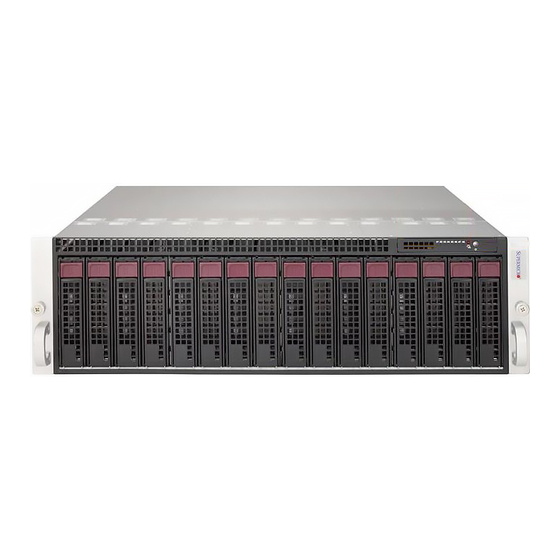
Page 11: Chassis Front
Chapter 1: Introduction Chassis Front The illustration below shows the features included on the front of the chassis. Figure 1-2. Front View Chassis Front Features Item Features Description Control Panel Power buttons and status indicators; details on the previous page Sixteen 3.5"... -
Page 12: Chassis Rear
SuperServer 5039MC-H8TRF User's Manual Chassis Rear The illustration below shows the features included on the rear of the chassis. Computing nodes and power supply modules display status lights. Figure 1-3. Rear View Chassis Rear Features Item Features Description Each node features a power button, two LAN ports, one dedicated IPMI LAN port, 1 –... -
Page 13: Connecting To A Node
Chapter 1: Introduction Figure 1-4. Node I/O Features Node I/O Features Item Description JKVM1 JUIDB1 Connecting to a Node USB, COM, and VGA port capabilities can be added to any node through the KVM port on the rear. Plug in the adapter (dongle) to use these ports. Figure 1-5. -
Page 14: Motherboard Layout
SuperServer 5039MC-H8TRF User's Manual 1.5 Motherboard Layout Below is a layout of the X11SCD-F motherboard with jumper, connector, and LED locations shown. See the table on the following page for descriptions. For detailed descriptions, pinout information, and jumper settings, refer to Chapter 4. -
Page 15: Quick Reference Table
Chapter 1: Introduction Quick Reference Table Jumper Description Default Setting Open (Normal) JBT1 CMOS Clear Closed: Clear CMOS JPG1 Onboard VGA Enable/Disable Pins 1-2 (Enabled) JPME2 Manufacturing Mode Pins 1-2 (Normal) JWD1 Watch Dog Timer Pins 1-2 (Reset) Pins 1-2 (Enabled) JPO1 CPU throttle when PWR_FAIL Pins 2-3 Disable (Default) -
Page 16: System Block Diagram
SuperServer 5039MC-H8TRF User's Manual System Block Diagram PCIe3.0_x8 SVID PCIe x8 MLP SLOT IMVP8 IMVP8 8.0GT/s INTEL LGA1151 DDR4 (CHA) DIMMA0 DIMMA1 PCIe3.0_x8 (Socket-H4) 2666MHz PCIe x8 SLOT(open end) 8.0GT/s DDR4 (CHB) DIMMB0 DIMMB1 2666MHz x4 DMI 8GT/s 2 SAS PORTS... -
Page 17: Where To Get Replacement Components
(http://www.supermicro.com/ support/rma/). Whenever possible, repack the chassis in the original Supermicro carton, using the original packaging material. If these are no longer available, be sure to pack the chassis securely, using packaging material to surround the chassis so that it does not shift within the carton and become damaged during shipping. -
Page 18: Chapter 2 Server Installation
SuperServer 5039MC-H8TRF User's Manual Chapter 2 Server Installation 2.1 Overview This chapter provides advice and instructions for mounting your system in a server rack. Caution: Electrostatic Discharge (ESD) can damage electronic components. To prevent such damage to PCBs (printed circuit boards), it is important to use a grounded wrist strap, handle all PCBs by their edges, and keep them in anti-static bags when not in use. -
Page 19: Server Precautions
Chapter 2: Server Installation • Always make sure the rack is stable before extending a server or other component from the rack. • You should extend only one server or component at a time - extending two or more simul- taneously may cause the rack to become unstable. -
Page 20: Circuit Overloading
SuperServer 5039MC-H8TRF User's Manual Circuit Overloading Consideration should be given to the connection of the equipment to the power supply circuitry and the effect that any possible overloading of circuits might have on overcurrent protection and power supply wiring. Appropriate consideration of equipment nameplate ratings should be used when addressing this concern. -
Page 21: Installing The Rails
Chapter 2: Server Installation 2.3 Installing the Rails There are a variety of rack units on the market, which may require a slightly different assembly procedure. This rail set fits a rack between 26.8" and 36.4" deep. The following is a basic guideline for installing the system into a rack with the rack mounting hardware provided. -
Page 22: Releasing The Inner Rail
SuperServer 5039MC-H8TRF User's Manual Releasing the Inner Rail Each inner rail has a locking latch. This latch prevents the server from coming completely out of the rack when the chassis is pulled out for servicing. To mount the rail onto the chassis, first release the inner rail from the outer rails. -
Page 23: Installing The Inner Rails On The Chassis
Chapter 2: Server Installation Installing the Inner Rails on the Chassis Installing the Inner Rails 1. Identify the left and right inner rails. They are labeled. 2. Place the inner rail firmly against the side of the chassis, aligning the hooks on the side of the chassis with the holes in the inner rail. -
Page 24: Installing The Outer Rails Onto The Rack
SuperServer 5039MC-H8TRF User's Manual Installing the Outer Rails onto the Rack Each end of the assembled outer rail includes a bracket with hooks and spring-loaded pegs to fit into the square holes in your rack. Installing the Outer Rail 1. Press upward on the locking tab at the rear end of the middle rail. -
Page 25: Installing The Chassis Into A Rack
Chapter 2: Server Installation 2.4 Installing the Chassis into a Rack Once rails are attached to the chassis and the rack, you can install the server. Warning: Mounting the system into the rack requires at least two people to support the chassis during installation. -
Page 26: Removing The Chassis From The Rack
SuperServer 5039MC-H8TRF User's Manual Removing the Chassis from the Rack Caution! The system is heavy. It is dangerous for a single person to remove it from the rack. Have sufficient personnel or use a lift to support the chassis. 1. Pull the chassis forward out the front of the rack until it stops. -
Page 27: Chapter 3 Maintenance And Component Installation
Chapter 3: Maintenance and Component Installation Chapter 3 Maintenance and Component Installation This chapter provides instructions on installing and replacing main system components. To prevent compatibility issues, only use components that match the specifications and/or part numbers given. Installation or replacement of most components require that power first be removed from the system. -
Page 28: Accessing The System
SuperServer 5039MC-H8TRF User's Manual 3.2 Accessing the System The chassis contains eight computing nodes, each removable from the rear of the chassis while the others continue operating. Removing a Computing Node The two storage drives controlled by the node will power down upon removal. -
Page 29: Removing The Chassis Cover
Chapter 3: Maintenance and Component Installation Removing the Chassis Cover You can access some chassis components, such as fans, by removing the cover. Screws Figure 3-2. Removing the Chassis Cover Removing the Chassis Cover The chassis top cover can be lifted off after removing three screws. Caution: Except for short periods of time, do not operate the server without the cover in place. -
Page 30: Motherboard Components
2666MHz in four DIMM slots. Populating the DIMM slots with pairs of memory modules of the same type, speed, and size will result in interleaved memory, which improves performance. Check the Supermicro website for possible updates to memory support. DIMM Module Population Configuration For optimal memory performance, follow the table below when populating memory. -
Page 31: Dimm Module Population Sequence
Chapter 3: Maintenance and Component Installation DIMM Module Population Sequence When installing memory modules, the DIMM slots must be populated in the following order: DIMMB2, DIMMA2, then DIMMB1 and DIMMA1. The blue slots must be populated first. Towards the CPU DIMMA1 DIMMA2 (Blue Slot) DIMMB1... -
Page 32: Install Procedure
SuperServer 5039MC-H8TRF User's Manual Install Procedure Installing Memory ESD Precautions Electrostatic Discharge (ESD) can damage electronic com ponents, including memory modules. To avoid damaging DIMM modules, it is important to handle them carefully. The following measures are generally sufficient. •... -
Page 33: Expansion Module
Chapter 3: Maintenance and Component Installation Expansion Module Each of the eight nodes includes a single MicroLP expansion module providing two LAN connections. Currently, there are four supported for the 5039MC-H8TRF system: • One PCI-E 3.0 x8 open end slot •... -
Page 34: Motherboard Battery
SuperServer 5039MC-H8TRF User's Manual Motherboard Battery The motherboard uses non-volatile memory to retain system information when system power is removed. This memory is powered by a lithium battery residing on the motherboard. Replacing the Battery Begin by removing power from the system as described in section 3.1. -
Page 35: Chassis Components
Chapter 3: Maintenance and Component Installation 3.4 Chassis Components This section provides instructions on installing and replacing system components. To assure compatibility, only use components that match the specifications or part numbers given. Corresponding Nodes, Fans and Hard Drives The SC938BH-R1620B chassis contains eight individual nodes each containing a motherboard. Each node controls two storage drives and shares a fan with the node beside it. -
Page 36: Storage Drives
Blinking at 1 Hz Attention state—do not remove NVMe device (not supported in VMD mode) Note: Enterprise level hard disk drives are recommended for use in Supermicro chassis and servers. For information on recommended HDDs, visit the Supermicro website at https://www. - Page 37 Chapter 3: Maintenance and Component Installation Removing a Hot-Swap Drive Carrier from the Chassis 1. Press the release button on the drive carrier, which will extend the drive carrier handle. 2. Use the drive carrier handle to pull the drive out of the chassis. Figure 3-6.
- Page 38 SuperServer 5039MC-H8TRF User's Manual Removing a Hot-Swap Drive Carrier from the Chassis 1. Press the release button on the drive carrier, which will extend the drive carrier handle. 2. Use the drive carrier handle to pull the drive out of the chassis.
- Page 39 Chapter 3: Maintenance and Component Installation Installing a Drive 1. Remove the dummy drive, which comes pre-installed in the drive carrier, by removing the screws securing the dummy drive to the carrier. These screws are not used to mount the actual drive. Dummy Drive Drive Carrier Screw...
-
Page 40: Checking The Temperature Of An Nvme M.2 Drive
SuperServer 5039MC-H8TRF User's Manual Checking the Temperature of an NVMe M.2 Drive Checking an NVMe M.2 drive using IPMI • IPMI > Server Health > Sensor Reading > M2NVMeSSD Temp1/2 – Shows the tempera- tures of all NVMe M.2 drives. -
Page 41: System Cooling
2. Squeeze both release tabs on the top of the fan module and pull it out. 3. Replace the failed fan with an identical fan, available from Supermicro. Push the new fan into the housing, making sure the air flow direction is the same. -
Page 42: Air Shroud
SuperServer 5039MC-H8TRF User's Manual Installing the Air Shroud Air shrouds and air blocks concentrate airflow to maximize fan efficiency. Air block is pre- installed and may be uninstalled by removing the two screws. Installing the Air Shroud 1. Power down the node and remove it. If an expansion card is used, install it first. -
Page 43: Power Supply
The chassis features redundant power supplies. They are hot-swappable, meaning they can be changed without powering down the system. New units can be ordered directly from Supermicro or authorized distributors. These power supplies are auto-switching capable. This feature enables them to automatically sense the input voltage and operate at a 100-120v or 180-240v. -
Page 44: Pci Expansion Cards
SuperServer 5039MC-H8TRF User's Manual PCI Expansion Cards The system supports one low-profile PCI-E card in each of the eight nodes with the included riser card (RSC-RR1U-E16). Installing an Expansion Card 1. Power-down the node and remove it. 2. Remove the three screws that secure the PCI bracket to the motherboard tray. - Page 45 Chapter 3: Maintenance and Component Installation Screws PCI Slot Bracket Expansion Card Motherboard Tray Node Figure 3-14. Installing an Expansion Card Chassis Slots...
-
Page 46: Chapter 4 Motherboard Connections
SuperServer 5039MC-H8TRF User's Manual Chapter 4 Motherboard Connections This section describes the connections on the motherboard and provides pinout definitions. Note that depending on how the system is configured, not all connections are required. The LEDs on the motherboard are also described here. A motherboard layout indicating component locations may be found in Chapter 1. - Page 47 Chapter 4: Motherboard Connections SAS Ports The X11SCD-F motherboard has two Serial Attached SCSI 3.0 ports (SAS0 and SAS1). M.2 Slot There are two M.2 slots on the motherboard. M.2 is formerly known as Next Generation Form Factor (NGFF). They are designed for internal mounting devices and provide M-Key 2280/22110 support dedicated for SSD devices with the PCI-E 3.0 x4 or SATA 3 interface.
-
Page 48: Rear Input/Output Ports
SuperServer 5039MC-H8TRF User's Manual 4.3 Rear Input/Output Ports Rear I/O Ports The rear of each node offers two RJ45 Gb Ethernet LAN ports, control switches, and a KVM port. Figure 4-1. Rear I/O Ports Rear I/O Ports Item Description JKVM1... - Page 49 Note: UID can also be triggered via IPMI on the motherboard. For more information on IPMI, please refer to the IPMI User's Guide posted on our website at https://www.supermicro.com/ support/manuals/. UID Button Pin Definitions...
-
Page 50: Jumpers
SuperServer 5039MC-H8TRF User's Manual 4.4 Jumpers Explanation of Jumpers To modify the operation of the motherboard, jumpers are used to choose between optional settings. Jumpers create shorts between two pins to change the function associated with it. Pin 1 is identified with a square solder pad on the printed circuit board. See the motherboard layout page for jumper locations. - Page 51 Chapter 4: Motherboard Connections ME Manufacturing Mode Close JPME2 to bypass SPI flash security and force the system to use the Manufacturing Mode, which will allow the user to flash the system firmware from a host server to modify system settings. Refer to the table below for jumper settings. Manufacturing Mode Jumper Settings Jumper Setting...
-
Page 52: Led Indicators
SuperServer 5039MC-H8TRF User's Manual 4.5 LED Indicators Onboard Power LED The Onboard Power LED indicator is located at SW2. When this LED is lit, it means power is present on the motherboard. Be sure to turn off the system and unplug the power cord(s) before removing or installing components. -
Page 53: Chapter 5 Software
USB/SATA DVD drive, or a USB flash drive, or the IPMI KVM console. 2. Retrieve the proper RST/RSTe driver. Go to the Supermicro web page for your motherboard and click on "Download the Latest Drivers and Utilities", select the proper driver, and copy it to a USB flash drive. - Page 54 SuperServer 5039MC-H8TRF User's Manual 4. During Windows Setup, continue to the dialog where you select the drives on which to install Windows. If the disk you want to use is not listed, click on “Load driver” link at the bottom left corner.
-
Page 55: Driver Installation
The Supermicro website contains drivers and utilities for your system at https://www. supermicro.com/wftp/driver. Some of these must be installed, such as the chipset driver. After accessing the website, go into the CDR_Images (in the parent directory of the above link) and locate the ISO file for your motherboard. Download this file to to a USB flash drive or a DVD. -
Page 56: Superdoctor ® 5
5.3 SuperDoctor ® The Supermicro SuperDoctor 5 is a program that functions in a command-line or web-based interface for Windows and Linux operating systems. The program monitors such system health information as CPU temperature, system voltages, system power consumption, fan speed, and provides alerts via email or Simple Network Management Protocol (SNMP). -
Page 57: Ipmi
Health drop-down menu. To access the other nodes within the same enclosure, click the IP address of the other nodes. In IPMI CLI view, typing the command "SMCIPMITool -tp info", allows the MCU information of all eight nodes to be displayed. For general documentation and information on IPMI, please visit our website at: http://www.supermicro.com/products/nfo/IPMI.cfm. -
Page 58: Chapter 6 Uefi Bios
SuperServer 5039MC-H8TRF User's Manual Chapter 6 UEFI BIOS 6.1 Introduction This chapter describes the AMIBIOS™ Setup utility for the X11SCD-F motherboard and provides the instructions on navigating the setup screens. The BIOS is stored in a flash chip and can be easily upgraded using a flash program. - Page 59 HH:MM:SS format. Note: The time is in the 24-hour format. For example, 5:30 P.M. appears as 17:30:00. The date's default value is 01/01/2016 after RTC reset. Supermicro X11SCD-F (Motherboard model) BIOS Version Build Date (of the BIOS) CPLD (Complex Programmable Logic Device) Version: This item displays the CPLD version used in the system.
-
Page 60: Advanced Setup Configurations
SuperServer 5039MC-H8TRF User's Manual 6.3 Advanced Setup Configurations Use the arrow keys to select the Advanced tab and press <Enter> to access the submenu items. Caution: Take caution when changing the Advanced settings. An incorrect value, a very high DRAM frequency, or an incorrect DRAM timing setting may make the system unstable. If this occurs, revert to the manufacture default settings. - Page 61 Chapter 6: UEFI BIOS Option ROM Messages Use this feature to set the display mode for the Option ROM. Select Keep Current to display the current AddOn ROM setting. Select Force BIOS to use the Option ROM display set by the system BIOS.
- Page 62 SuperServer 5039MC-H8TRF User's Manual CPU Configuration The following CPU information will display: • Processor type • CPU Signature • Microcode Revision • CPU Speed • L1 Data Cache • L1 Instruction Cache • L2 Cache • L3 Cache •...
- Page 63 Chapter 6: UEFI BIOS Adjacent Cache Line Prefetch The CPU prefetches the cache line for 64 bytes if this feature is set to Disabled. The CPU prefetches both cache lines for 128 bytes as comprised if this feature is set to Enabled. The options are Disabled and Enabled.
- Page 64 SuperServer 5039MC-H8TRF User's Manual C States Use this feature to enable the C-State of the CPU. The options are Disabled and Enabled. Enhanced C-states Use this feature to enable the enhanced C-State of the CPU. The options are Disabled and Enabled.
- Page 65 Chapter 6: UEFI BIOS ACPI T-States Use this feature to select Enabled to support CPU throttling by the operating system to reduce power consumption. The options are Disabled and Enabled. Chipset Configuration Warning: Setting the wrong values in the sections below may cause the system to malfunction. System Agent (SA) Configuration The following information will display: •...
- Page 66 SuperServer 5039MC-H8TRF User's Manual Memory Scrambler Use this feature to enable or disable memory scrambler support. The options are Dis- abled and Enabled. Fast Boot Use this feature to enable or disable fast path through the memory reference code. The options are Disabled and Enabled.
- Page 67 Chapter 6: UEFI BIOS Power Limit Value Use this feature to set the upper limit on the power supplied by the PCIE slot. Press "+" or "-" on your keyboard to change this value. The default setting is 75. Power Limit Scale Use this feature to select the scale used for the slot power limit value.
- Page 68 SuperServer 5039MC-H8TRF User's Manual Power Limit Value Use this feature to set the upper limit on the power supplied by the PCIE slot. Press "+" or "-" on your keyboard to change this value. The default setting is 75.Power Limit ScalePower Limit Scale Use this feature to select the scale used for the slot power limit value.
- Page 69 Chapter 6: UEFI BIOS PCH-IO Configuration PCI Express Configuration DMI Link ASPM Control Use this feature to set the ASPM (Active State Power Management) state on the SA (System Agent) side of the DMI Link. The options are Disabled, L0s, L1, L0sL1, and Auto. Peer Memory Write Enable Use this feature to enable or disable peer memory write.
- Page 70 SuperServer 5039MC-H8TRF User's Manual JMD2:M.2-H PCIe Speed Use this feature to select the PCI Express port speed. The options are Auto, Gen1, Gen2, and Gen3. Port 61h Bit-4 Emulation Select Enabled to enable the emulation of Port 61h bit-4 toggling in SMM (System Man- agement Mode).
- Page 71 Chapter 6: UEFI BIOS Change Settings This feature specifies the base I/O port address and the Interrupt Request address of a serial port specified by the user. Select Auto to allow the BIOS to automatically assign the base I/O and IRQ address. The options are Auto, (IO=3F8h; IRQ=3;), (IO=2F8h; IRQ=3;), (IO=3E8h;...
- Page 72 SuperServer 5039MC-H8TRF User's Manual Parity A parity bit can be sent along with regular data bits to detect data transmission errors. Select Even if the parity bit is set to 0, and the number of 1's in data bits is even. Select Odd if the parity bit is set to 0, and the number of 1's in data bits is odd.
- Page 73 Chapter 6: UEFI BIOS Legacy OS Redirection Resolution Use this feature to select the number of rows and columns used in Console Redirection for legacy OS support. The options are 80x24 and 80x25. Redirection After BIOS POST Use this feature to enable or disable legacy console redirection after BIOS POST. When set to BootLoader, legacy console redirection is disabled before booting the OS.
- Page 74 SuperServer 5039MC-H8TRF User's Manual Flow Control Use this feature to set the flow control for Console Redirection to prevent data loss caused by buffer overflow. Send a "Stop" signal to stop sending data when the receiving buffer is full. Send a "Start" signal to start sending data when the receiving buffer is empty. The options are None, Hardware RTS/CTS, and Software Xon/Xoff.
- Page 75 Chapter 6: UEFI BIOS Serial ATA Port 0 Hot Plug Set this feature to Enable for hot plug support, which will allow the user to replace a SATA drive without shutting down the system. The options are Disabled and Enabled. Serial ATA Port 0 Spin Up Device Set this feature to enable or disable the PCH to initialize the device.
- Page 76 SuperServer 5039MC-H8TRF User's Manual Serial ATA Port 2 Hot Plug Set this feature to Enable for hot plug support, which will allow the user to replace a SATA drive without shutting down the system. The options are Disabled and Enabled.
- Page 77 Chapter 6: UEFI BIOS • ME Firmware Status #1 • ME Firmware Status #2 • Current State • Error Code ACPI Settings WHEA Support Select Enabled to support the Windows Hardware Error Architecture (WHEA) platform and provide a common infrastructure for the system to handle hardware errors within the Windows OS environment in order to reduce system crashes and enhance system recovery and health monitoring.
- Page 78 SuperServer 5039MC-H8TRF User's Manual USB Configuration USB Configuration USB Module Version: 21 USB Controllers: 1 XHCI USB Devices: 2 Keyboards, 1 Mouse, 1 Hub Legacy USB Support Select Enabled to support onboard legacy USB devices. Select Auto to disable legacy support if there are no legacy USB devices present.
- Page 79 Chapter 6: UEFI BIOS Above 4G MMIO BIOS Assignment Select Enabled to decode a PCI device that supports 64-bit in the space above 4G Address. The options are Enabled and Disabled. VGA Priority Use this feature to select VGA priority when multiple VGA devices are detected. Select Onboard to give priority to your onboard video device.
- Page 80 SuperServer 5039MC-H8TRF User's Manual Ipv6 HTTP Support Select Enabled to enable IPv6 HTTP boot support. The options are Disabled and Enabled. IPSEC Certificate The feature appears if Network Stack is enabled. Internet Protocol Security (IPSEC) offers a secure connection for remote computers using a secure tunnel. The options are Disabled and Enabled.
- Page 81 TPM 2.0 will restrict support for TPM 2.0 devices. Select Auto to enable support for both versions. The options are TPM 1.2, TPM 2.0, Auto. SMCI BIOS-Based TPM Provision Support Use this feature to enable the Supermicro TPM Provision support. The options are Disabled and Enabled.
- Page 82 SuperServer 5039MC-H8TRF User's Manual HTTP BOOT Configuration HTTP BOOT Configuration Http Boot One Time Use this feature to create the HTTP boot option. The options are Disabled and Enable. Input the desrciption Highlight the feature and press enter to create a description.
- Page 83 Chapter 6: UEFI BIOS Certification GUID Use this feature to input the certification GUID. Commit Changes and Exit Use this feature to save all changes and exit TLS settings. Discard Changes and Exit Use this feature to discard all changes and exit TLS settings. ...
-
Page 84: Ipmi
SuperServer 5039MC-H8TRF User's Manual 6.4 IPMI Use this tab page to configure Intelligent Platform Management Interface (IPMI) settings. The following items will be displayed: • IPMI Firmware Revision • Status of BMC System Event Log Enabling/Disabling Options SEL Components Select Enabled for all system event logging at boot up. The options are Disabled and Enabled. - Page 85 Chapter 6: UEFI BIOS When SEL is Full This feature allows the user to determine what the BIOS should do when the system event log is full. Select Erase Immediately to erase all events in the log when the system event log is full.
- Page 86 SuperServer 5039MC-H8TRF User's Manual Station MAC Address This feature displays the Station MAC address for this computer. Mac addresses are 6 two-digit hexadecimal numbers. Gateway IP Address This feature displays the Gateway IP address for this computer. This should be in decimal and in dotted quad form (i.e., 192.168.10.253).
-
Page 87: Security
Chapter 6: UEFI BIOS 6.5 Security Use this tab page to configure Security settings. Administrator Password Use this feature to set the administrator password which is required to enter the BIOS setup utility. The length of the password should be from 3 to 20 characters long. Password Check Select Setup for the system to check for a password at Setup. - Page 88 SuperServer 5039MC-H8TRF User's Manual Secure Boot Mode This feature allows the user to select the desired secure boot mode for the system. The options are Standard and Custom. *If Secure Boot Mode is set to Customized, Key Management features are available...
- Page 89 Chapter 6: UEFI BIOS Secure Boot variable Platform Key (PK) Details Select this feature to view the details of the Platform Key. Export Select Yes to export a PK from a file on an external media. Update Select Yes to load a factory default PK or No to load from a file on an external media. Delete Select Ok to remove the PK and then the system will reset to Setup/Audit Mode.
- Page 90 SuperServer 5039MC-H8TRF User's Manual Delete Select Ok to remove the db and then the system will reset to Setup/Audit Mode. Forbidden Signatures Details Select this feature to view the details of the dbx. Export Select Yes to export a dbx from a file on an external media.
- Page 91 Chapter 6: UEFI BIOS OsRecovery Signatures Details Select this feature to view the details of the dbr. Export Select Yes to export a dbr from a file on an external media. Update Select Yes to load a factory default dbr or No to load from a file on an external media. Append Select Yes to add the dbr from the manufacturer's defaults list to the existing dbr.
-
Page 92: Event Logs
SuperServer 5039MC-H8TRF User's Manual 6.6 Event Logs Use this tab page to configure Event Log settings. Change SMBIOS Event Log Settings Enabling/Disabling Options Smbios Event Log Change this feature to enable or disable all features of the SMBIOS Event Logging during system boot. - Page 93 Chapter 6: UEFI BIOS Smbios Event Log Standard Settings Log System Boot Event Select Enabled to log system boot events. The options are Enabled and Disabled. MECI (Multiple Event Count Increment) Enter the increment value for the multiple event counter. Enter a number between 1 to 255. The default setting is 1.
-
Page 94: Boot
SuperServer 5039MC-H8TRF User's Manual 6.7 Boot Use this tab page to configure Boot Settings. Setup Prompt Timeout Use this feature to specify the length of time (the number of seconds) for the BIOS to wait before rebooting the system when the setup activation key is pressed. Enter the value of 65535 (0xFFFF) for the BIOS to wait indefinitely. - Page 95 Chapter 6: UEFI BIOS Fixed BOOT ORDER Priorities This option prioritizes the order of bootable devices that the system can boot from. Press <Enter> on each entry from top to bottom to select devices. • LEGACY/UEFI/DUAL Boot Order #1 • LEGACY/UEFI/DUAL Boot Order #2 •...
-
Page 96: Save & Exit
SuperServer 5039MC-H8TRF User's Manual 6.8 Save & Exit Use this tab page to configure Save & Exit settings. Save Options Discard Changes and Exit Select this feature to quit the BIOS Setup without making any permanent changes to the system configuration and reboot the computer. Select Discard Changes and Exit from the Exit menu and press <Enter>. - Page 97 Chapter 6: UEFI BIOS Default Options Restore Defaults To set this feature, select Restore Optimized Defaults and press <Enter>. These are factory settings designed for maximum system performance but not for maximum stability. Save as User Defaults To set this feature, select Save as User Defaults from the Exit menu and press <Enter>. This enables the user to save any changes to the BIOS setup for future use.
-
Page 98: Appendix A Bios Error Codes
When BIOS performs the Power On Self Test, it writes checkpoint codes to I/O port 0080h. If the computer cannot complete the boot process, a diagnostic card can be attached to the computer to read I/O port 0080h (Supermicro p/n AOC-LPC80-20). For information on AMI updates, please refer to http://www.ami.com/products/. -
Page 99: Appendix B Standardized Warning Statements For Ac Systems
Supermicro's Technical Support department for assistance. Only certified technicians should attempt to install or configure components. Read this appendix in its entirety before installing or configuring components in the Supermicro chassis. These warnings may also be found on our website at http://www.supermicro.com/about/... - Page 100 Appendix B: Standardized Warning Statements Warnung WICHTIGE SICHERHEITSHINWEISE Dieses Warnsymbol bedeutet Gefahr. Sie befinden sich in einer Situation, die zu Verletzungen führen kann. Machen Sie sich vor der Arbeit mit Geräten mit den Gefahren elektrischer Schaltungen und den üblichen Verfahren zur Vorbeugung vor Unfällen vertraut. Suchen Sie mit der am Ende jeder Warnung angegebenen Anweisungsnummer nach der jeweiligen Übersetzung in den übersetzten Sicherheitshinweisen, die zusammen mit diesem Gerät ausgeliefert wurden.
- Page 101 SuperServer 5039MC-H8TRF User's Manual . ٌ ا ك ً ف حالة و ٌ يك أى تتسبب ف اصابة جسذ ة ٌ هذا الزهز ع ٌ خطز !تحذ ز قبل أى تعول عىل أي هعذات،يك عىل علن بالوخاطز ال ا ٌجوة عي الذوائز...
- Page 102 Appendix B: Standardized Warning Statements Warnung Vor dem Anschließen des Systems an die Stromquelle die Installationsanweisungen lesen. ¡Advertencia! Lea las instrucciones de instalación antes de conectar el sistema a la red de alimentación. Attention Avant de brancher le système sur la source d'alimentation, consulter les directives d'installation. .יש...
- Page 103 SuperServer 5039MC-H8TRF User's Manual Warnung Dieses Produkt ist darauf angewiesen, dass im Gebäude ein Kurzschluss- bzw. Überstromschutz installiert ist. Stellen Sie sicher, dass der Nennwert der Schutzvorrichtung nicht mehr als: 250 V, 20 A beträgt. ¡Advertencia! Este equipo utiliza el sistema de protección contra cortocircuitos (o sobrecorrientes) del edificio.
- Page 104 Appendix B: Standardized Warning Statements Power Disconnection Warning Warning! The system must be disconnected from all sources of power and the power cord removed from the power supply module(s) before accessing the chassis interior to install or remove system components. 電源切断の警告...
- Page 105 SuperServer 5039MC-H8TRF User's Manual يجب فصم اننظاو من جميع مصادر انطاقت وإ ز انت سهك انكهرباء من وحدة امداد انطاقت قبم انىصىل إىن امنناطق انداخهيت نههيكم نتثبيج أو إ ز انت مكىناث الجهاز 경고! 시스템에 부품들을 장착하거나 제거하기 위해서는 섀시 내부에 접근하기 전에 반드시 전원...
- Page 106 Appendix B: Standardized Warning Statements Attention Il est vivement recommandé de confier l'installation, le remplacement et la maintenance de ces équipements à des personnels qualifiés et expérimentés. !אזהרה .צוות מוסמך בלבד רשאי להתקין, להחליף את הציוד או לתת שירות עבור הציוד واملدربيه...
- Page 107 SuperServer 5039MC-H8TRF User's Manual Warnung Diese Einheit ist zur Installation in Bereichen mit beschränktem Zutritt vorgesehen. Der Zutritt zu derartigen Bereichen ist nur mit einem Spezialwerkzeug, Schloss und Schlüssel oder einer sonstigen Sicherheitsvorkehrung möglich. ¡Advertencia! Esta unidad ha sido diseñada para instalación en áreas de acceso restringido. Sólo puede obtenerse acceso a una de estas áreas mediante la utilización de una herramienta especial,...
- Page 108 Appendix B: Standardized Warning Statements Battery Handling Warning! There is the danger of explosion if the battery is replaced incorrectly. Replace the battery only with the same or equivalent type recommended by the manufacturer. Dispose of used batteries according to the manufacturer's instructions 電池の取り扱い...
- Page 109 SuperServer 5039MC-H8TRF User's Manual هناك خطر من انفجار يف حالة اسحبذال البطارية بطريقة غري صحيحة فعليل اسحبذال البطارية فقط بنفس النىع أو ما يعادلها مام أوصث به الرشمة املصنعة جخلص من البطاريات املسحعملة وفقا لحعليامت الرشمة الصانعة 경고! 배터리가 올바르게 교체되지 않으면 폭발의 위험이 있습니다. 기존 배터리와 동일하거나 제...
- Page 110 Appendix B: Standardized Warning Statements ¡Advertencia! Puede que esta unidad tenga más de una conexión para fuentes de alimentación. Para cortar por completo el suministro de energía, deben desconectarse todas las conexiones. Attention Cette unité peut avoir plus d'une connexion d'alimentation. Pour supprimer toute tension et tout courant électrique de l'unité, toutes les connexions d'alimentation doivent être débranchées.
- Page 111 SuperServer 5039MC-H8TRF User's Manual Backplane Voltage Warning! Hazardous voltage or energy is present on the backplane when the system is operating. Use caution when servicing. バックプレーンの電圧 システムの稼働中は危険な電圧または電力が、 バックプレーン上にかかっています。 修理する際には注意く ださい。 警告 当系统正在进行时,背板上有很危险的电压或能量,进行维修时务必小心。 警告 當系統正在進行時,背板上有危險的電壓或能量,進行維修時務必小心。 Warnung Wenn das System in Betrieb ist, treten auf der Rückwandplatine gefährliche Spannungen oder Energien auf.
- Page 112 Appendix B: Standardized Warning Statements هناك خطز مه التيار الكهزبايئ أوالطاقة املىجىدة عىل اللىحة عندما يكىن النظام يعمل كه حذ ر ا عند خدمة هذا الجهاس 경고! 시스템이 동작 중일 때 후면판 (Backplane)에는 위험한 전압이나 에너지가 발생 합니다. 서비스 작업 시 주의하십시오. Waarschuwing Een gevaarlijke spanning of energie is aanwezig op de backplane wanneer het systeem in gebruik is.
- Page 113 SuperServer 5039MC-H8TRF User's Manual תיאום חוקי החשמל הארצי !אזהרה .התקנת הציוד חייבת להיות תואמת לחוקי החשמל המקומיים והארציים تركيب املعدات الكهربائية يجب أن ميتثل للقىاويه املحلية والىطىية املتعلقة بالكهرباء 경고! 현 지역 및 국가의 전기 규정에 따라 장비를 설치해야 합니다.
- Page 114 Appendix B: Standardized Warning Statements Attention La mise au rebut ou le recyclage de ce produit sont généralement soumis à des lois et/ou directives de respect de l'environnement. Renseignez-vous auprès de l'organisme compétent. סילוק המוצר !אזהרה .סילוק סופי של מוצר זה חייב להיות בהתאם להנחיות וחוקי המדינה التخلص...
- Page 115 SuperServer 5039MC-H8TRF User's Manual Warnung Gefährlich Bewegende Teile. Von den bewegenden Lüfterblätter fern halten. Die Lüfter drehen sich u. U. noch, wenn die Lüfterbaugruppe aus dem Chassis genommen wird. Halten Sie Finger, Schraubendreher und andere Gegenstände von den Öffnungen des Lüftergehäuses entfernt.
- Page 116 Verbindungskabeln, Stromkabeln und/oder Adapater, die Ihre örtlichen Sicherheitsstandards einhalten. Der Gebrauch von anderen Kabeln und Adapter können Fehlfunktionen oder Feuer verursachen. Die Richtlinien untersagen das Nutzen von UL oder CAS zertifizierten Kabeln (mit UL/CSA gekennzeichnet), an Geräten oder Produkten die nicht mit Supermicro gekennzeichnet sind.
- Page 117 .قيرح وأ لطع يف ببستي دق ىرخأ تالوحمو تالباك يأ مادختسا .ميلسلا سباقلاو لصوملا مجح لبق نم ةدمتعملا تالباكلا مادختسا تادعملاو ةيئابرهكلا ةزهجألل ةمالسلا نوناق رظحيUL وأCSA ( ةمالع لمحت يتلاوUL/CSA) لبق نم ةددحملاو ةينعملا تاجتنملا ريغ ىرخأ تادعم يأ عمSupermicro.
- Page 118 사항을 준수하여 제공되거나 지정된 연결 혹은 구매 케이블, 전원 케이블 및 AC 어댑터를 사용하십시오. 다른 케이블이나 어댑터를 사용하면 오작동이나 화재가 발생할 수 있습니다. 전기 용품 안전법은 UL 또는 CSA 인증 케이블 (코드에 UL / CSA가 표시된 케이블)을 Supermicro 가 지정한 제품 이외의 전기 장치에 사용하는 것을 금지합니다. Stroomkabel en AC-Adapter...
-
Page 119: Appendix C System Specifications
Appendix C: System Specifications Appendix C System Specifications Processors (per node) Single socket H4 (LGA 1151) supports Intel Xeon E-2100 Core i3 Pentium Celeron processor, 16 Threads, 95W, Intel C246 Note: Please refer to the motherboard specifications pages on our website for updates to supported processors. BIOS 128Mb UEFI Memory (per node) - Page 120 SuperServer 5039MC-H8TRF User's Manual Power Supply Model: PWS-2K04A-1R, 80+ level Titanium, Dimensions (W x H x L): 76 x 40 x 336mm Total Output Power: 1000W/1800W/1980W/2000W Output Type: 27 Pairs Gold Finger Connector Input: 1000W: 100-127Vac / 12.5-9.5A / 50-60Hz 1800W: 200-220Vac / 10-9.5A / 50-60Hz...
-
Page 121: Appendix D Uefi Bios Recovery
Warning: Do not upgrade the BIOS unless your system has a BIOS-related issue. Flashing the wrong BIOS can cause irreparable damage to the system. In no event shall Supermicro be liable for direct, indirect, special, incidental, or consequential damages arising from a BIOS update. - Page 122 SuperServer 5039MC-H8TRF User Manual The file system supported by the recovery block is FAT (including FAT12, FAT16, and FAT32) which is installed on a bootable or non-bootable USB-attached device. However, the BIOS might need several minutes to locate the SUPER.ROM file if the media size becomes too large due to the huge volumes of folders and files stored in the device.
- Page 123 Appendix D: UEFI BIOS Recovery 3. After locating the healthy BIOS binary image, the system will enter the BIOS Recovery menu as shown below. Note: At this point, you may decide if you want to start the BIOS recovery. If you decide to proceed with BIOS recovery, follow the procedures below.
- Page 124 SuperServer 5039MC-H8TRF User Manual 5. After the BIOS recovery process is complete, press any key to reboot the system. 6. Using a different system, extract the BIOS package into a USB flash drive. 7. Press <Del> continuously during system boot to enter the BIOS Setup utility. From the top of the tool bar, select Boot to enter the submenu.
- Page 125 Appendix D: UEFI BIOS Recovery 8. When the UEFI Shell prompt appears, type fs# to change the device directory path. Go to the directory that contains the BIOS package you extracted earlier from Step 6. Enter flash.nsh BIOSname.### at the prompt to start the BIOS update process. Note: Do not interrupt this process until the BIOS flashing is complete.
-
Page 126: Appendix E Ipmi Crash Dump
In the event of a processor internal error (IERR) that crashes your system, you may want to provide information to support staff. You can download a crash dump of status information using IPMI. The IPMI manual is available at https://www.supermicro.com/solutions/IPMI.cfm. Check IPMI Error Log 1. - Page 127 Appendix E IPMI Crash Dump Downloading the Crash Dump File 1. In the IPMI interface, click the Miscellaneous tab, then the Trouble Shooting option. 2. Click the Dump button and wait five minutes for the file to be created. (No confirm ation message will appear.) 3.
Need help?
Do you have a question about the SuperServer 5039MC-H8TRF and is the answer not in the manual?
Questions and answers