Table of Contents
Advertisement
Quick Links
Advertisement
Table of Contents

Related Manuals for Supermicro SuperServer 5029P-WTR


Summary of Contents for Supermicro SuperServer 5029P-WTR
- Page 1 SuperServer ® 5029P-WTR USER'S MANUAL Revision 1.0a...
- Page 2 State of California, USA. The State of California, County of Santa Clara shall be the exclusive venue for the resolution of any such disputes. Supermicro's total liability for all claims will not exceed the price paid for the hardware product.
- Page 3 About this Manual This manual is written for professional system integrators and PC technicians. It provides information for the installation and use of the SuperServer 5029P-WTR. Installation and maintenance should be performed by experienced technicians only. Please refer to the 5029P-WTR server specifications page on our website for updates on supported memory, processors and operating systems (http://www.supermicro.com).
-
Page 4: Table Of Contents
Preface Contents Chapter 1 Introduction 1.1 Overview ..........................8 1.2 Unpacking the System ......................8 1.3 System Features ........................9 1.4 Server Chassis Features ....................10 Control Panel ........................10 Chassis Front ........................11 Chassis Rear ........................12 1.5 Motherboard Layout ......................13 Quick Reference Table ......................14 Chapter 2 Server Installation 2.1 Overview ..........................17 2.2 Preparing for Setup ......................17 Choosing a Setup Location ....................17... - Page 5 SuperServer 5029P-WTR User's Manual Overview of the Processor Socket Assembly ..............27 Overview of the Processor Heatsink Module (PHM) ............28 Attaching the Non-F Model Processor to the Processor Clip to Create the Processor Carrier Assembly .......................29 Attaching the Non-F Model Processor Carrier Assembly to the Heatsink to Form the Processor Heatsink Module (PHM) ...................30...
- Page 6 Preface 4.2 Front Control Panel ......................47 4.3 Ports and Headers ......................49 Rear I/O Ports ........................49 Connectors ........................52 Headers ..........................53 4.4 Jumpers ..........................56 Explanation of Jumpers ....................56 4.5 LED Indicators ........................58 Chapter 5 Software 5.1 OS Installation ........................60 Installing the Windows OS for a RAID System ..............60 Installing Windows to a Non-RAID System ..............60 5.2 Driver Installation ........................61 5.3 SuperDoctor...
- Page 7 SuperServer 5029P-WTR User's Manual Contacting Supermicro Headquarters Address: Super Micro Computer, Inc. 980 Rock Ave. San Jose, CA 95131 U.S.A. Tel: +1 (408) 503-8000 Fax: +1 (408) 503-8008 Email: marketing@supermicro.com (General Information) support@supermicro.com (Technical Support) Website: www.supermicro.com Europe Address: Super Micro Computer B.V.
-
Page 8: Overview
Rack Rail Mounting Kit MCP-290-00053-0N 1.2 Unpacking the System Inspect the box the SuperServer 5029P-WTR was shipped in and note if it was damaged in any way. If any equipment appears damaged, please file a damage claim with the carrier who delivered it. -
Page 9: System Features
Chapter 1: Introduction 1.3 System Features The following table provides you with an overview of the main features of the 5029P-WTR. Please refer to Appendix C for additional specifications. System Features Motherboard X11SPW-TF Chassis 825TQC-R609WB Intel® Xeon® Scalable and 2nd Gen Intel® Xeon® Scalable Processors with Thermal Design Power (TDP) of up to 205W and 28-cores Note: The X11SPW-TF motherboard does not support FPGA or Fabric processors. -
Page 10: Server Chassis Features
SuperServer 5029P-WTR User's Manual 1.4 Server Chassis Features Control Panel The switches and LEDs located on the control panel are described below. See Chapter 4 for details on the control panel connections. Figure 1-1. Control Panel View Control Panel Features... -
Page 11: Chassis Front
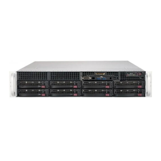
Chapter 1: Introduction Chassis Front The 825TQC-R609WB is a 2U rackmount chassis See the illustration below for the features included on the front of the chassis. Figure 1-2. Chassis Front View Front Chassis Features Item Feature Description 3.5" HDD Bay Internal Bay for 3.5"... -
Page 12: Chassis Rear
SuperServer 5029P-WTR User's Manual Chassis Rear The illustration below shows the features included on the rear of the chassis. Note: the 5029P-WTR server is shown below. The 5029P-WTR is the same but with a single power module only. Figure 1-3. Chassis Rear View... -
Page 13: Motherboard Layout
Chapter 1: Introduction 1.5 Motherboard Layout Below is a layout of the X11SPW-TF with jumper, connector and LED locations shown. See the table on the following page for descriptions. For detailed descriptions, pinout information and jumper settings, refer to Chapter 4. JWD1 USB7/8 (3.0) COM1... -
Page 14: Quick Reference Table
SuperServer 5029P-WTR User's Manual Quick Reference Table Jumper Description Default Setting JBT1 CMOS Clear Open (Normal) JPG1 VGA Enable/Disable Pins 1-2 (Enabled) JPME2 ME Manufacturing Mode Pins 1-2 (Normal) JPS1 SAS 3.0 Enable/Disable Pins 1-2 (Enabled) JPSAS1 SAS HDD Enable/Disable... - Page 15 M.2 Mounting Holes Internal Speaker/Buzzer S-SATA0~1 SATA 3.0 Ports with SATA DOM Power SXB1A, SXB1B, SXB1C Supermicro Proprietary WIO Left Add-on Card Slots SXB2 Supermicro Proprietary WIO Right Add-on Card Slot USB0/1 Back Panel Universal Serial Bus (USB) 2.0 Ports USB2/3, USB4/5 Front Accessible USB 2.0 Headers...
- Page 16 SuperServer 5029P-WTR User's Manual VCCP0 12v VR13 5+1 PHASE #F-1 #C-1 205W #E-1 #B-1 #D-1 #A-1 VCCP0 SNB CORE PECI:30 DDR-IV SOCKET ID:0 DMI3 PCI-E X8 G3 DMI3 PCI-E X16 G3 PCI-E X16 G3 Uplink #0~3 PCI-E X4 G3 6.0 Gb/S M.2 SSD...
-
Page 17: Chapter 2 Server Installation
Chapter 2: Server Installation Chapter 2 Server Installation 2.1 Overview This chapter provides advice and instructions for mounting your system in a server rack. If your system is not already fully integrated with processors, system memory etc., refer to Chapter 4 for details on installing those specific components. Caution: Electrostatic Discharge (ESD) can damage electronic components. -
Page 18: Server Precautions
SuperServer 5029P-WTR User's Manual • In single rack installations, stabilizers should be attached to the rack. In multiple rack in- stallations, the racks should be coupled together. • Always make sure the rack is stable before extending a server or other component from the rack. -
Page 19: Circuit Overloading
Chapter 2: Server Installation Circuit Overloading Consideration should be given to the connection of the equipment to the power supply circuitry and the effect that any possible overloading of circuits might have on overcurrent protection and power supply wiring. Appropriate consideration of equipment nameplate ratings should be used when addressing this concern. -
Page 20: Installing The Server Into A Rack
SuperServer 5029P-WTR User's Manual 2.3 Installing the Server into a Rack This section provides information on installing the 825TQC chassis into a rack unit with the quick-release rails provided. There are a variety of rack units on the market, which may mean the assembly procedure will differ slightly. -
Page 21: Installing The Inner Rail Extension
Chapter 2: Server Installation Installing the Inner Rail Extension The 825TQC chassis includes a set of inner rails in two sections: inner rails and inner rail extensions. The inner rails are pre-attached to the chassis, and do not interfere with normal use of the chassis if you decide not to use a server rack. - Page 22 SuperServer 5029P-WTR User's Manual Installing the Chassis into a Rack 1. Extend the outer rails as illustrated above. 2. Align the inner rails of the chassis with the outer rails on the rack. 3. Slide the inner rails into the outer rails, keeping the pressure even on both sides. When the chassis has been pushed completely into the rack, it should click into the locked position.
-
Page 23: Chapter 3 Maintenance And Component Installation
SuperServer 5029P-WTR User's Manual Chapter 3 Maintenance and Component Installation This chapter provides instructions on installing and replacing main system components. To prevent compatibility issues, only use components that match the specifications and/or part numbers given. Installation or replacement of most components require that power first be removed from the system. - Page 24 Chapter 3: Maintenance and Component Installation 7. Check that all ventilation openings on the top cover and the top of the chassis are clear and unobstructed. Warning: Except for short periods of time, do not operate the server without the cover in place. The chassis cover must be in place to allow for proper airflow and to prevent overheating.
-
Page 25: Motherboard Components
If you bought a CPU separately, make sure that you use an Intel-certified multi-directional heatsink only. • Refer to the Supermicro website for updates on CPU support. The Intel® Xeon® Scalable and 2nd Gen Intel® Xeon® Scalable ProcessorsSeries Processor Intel Xeon Processor (Non-Fabric Model) Note: All graphics, drawings, and pictures shown in this manual are for illustration only. -
Page 26: Overview Of The Processor Socket Assembly
Chapter 3: Maintenance and Component Installation Overview of the Processor Socket Assembly The processor socket assembly contains 1) the Intel SKX processor, 2) the processor clip, 3) the dust cover, and 4) the CPU socket. 1. SKX Processor 2. Processor Clip (the plastic processor package carrier used for the CPU) 3. -
Page 27: Overview Of The Processor Socket Assembly
SuperServer 5029P-WTR User's Manual Overview of the Processor Socket Assembly The processor socket assembly contains 1) the Intel SKX processor, 2) the processor clip, 3) the dust cover, and 4) the CPU socket. 1. SKX Processor 2. Processor Clip (the plastic processor package carrier used for the CPU) 3. -
Page 28: Overview Of The Processor Heatsink Module (Phm)
Chapter 3: Maintenance and Component Installation Overview of the Processor Heatsink Module (PHM) The Processor Heatsink Module (PHM) contains 1) a heatsink, 2) a processor clip, and 3) the SKX processor. 1. Heatsink 2. Processor Clip 3. SKX Processor Processor Heatsink Module (PHM) (Bottom View for a non-F Model) -
Page 29: Attaching The Non-F Model Processor To The Processor Clip To Create The Processor Carrier Assembly
SuperServer 5029P-WTR User's Manual Attaching the Non-F Model Processor to the Processor Clip to Create the Processor Carrier Assembly To properly install the CPU into the processor clip, please follow the steps below: 1. Locate pin 1 (notch A), which is the triangle located on the top of the processor clip. -
Page 30: Attaching The Non-F Model Processor Carrier Assembly To The Heatsink To Form The Processor Heatsink Module (Phm)
Chapter 3: Maintenance and Component Installation Attaching the Non-F Model Processor Carrier Assembly to the Heatsink to Form the Processor Heatsink Module (PHM) After you have made a processor carrier assembly by following the instructions on the previous page, please follow the steps below to mount the processor carrier assembly onto the heatsink to create the Processor Heatsink Module (PHM): 1. -
Page 31: Preparing The Cpu Socket For Installation
SuperServer 5029P-WTR User's Manual Preparing the CPU Socket for Installation This motherboard comes with the CPU socket pre-assembled in the factory. The CPU socket contains 1) a dust cover, 2) a socket bracket, 3) the CPU (P0) socket, and 4) a back plate. -
Page 32: Installing The Processor Heatsink Module (Phm)
Chapter 3: Maintenance and Component Installation Installing the Processor Heatsink Module (PHM) Once you have assembled the processor heatsink module (PHM) by following the instructions listed on page 26, you are ready to install the processor heatsink module (PHM) into the CPU socket on the motherboard. -
Page 33: Removing The Processor Heatsink Module (Phm) From The Motherboard
SuperServer 5029P-WTR User's Manual Removing the Processor Heatsink Module (PHM) from the Motherboard Before removing the processor heatsink module (PHM), unplug the power cord from the power outlet. 1. Using a T30 Torx-bit screwdriver, turn the screws on the PHM counterclockwise to loosen them from the socket, starting with the screw marked #4 (in the sequence of 4, 3, 2, 1). -
Page 34: Memory Installation
16GB RDIMM DRx4 16GB 32GB QRx4 2H-64GB 2666 2666 2666 RDIMM 3DS 8Rx4 4H-128GB LRDIMM QRx4 32GB 64GB QRx4 2H-64GB LRDIMM 3DS 8Rx4 4H-128GB Note: Visit the product page on the Supermicro website for possible updates to memory support (www.supermicro.com). -
Page 35: Ddr4 Memory Support For 82Xx/62Xx/52Xx/42Xx/32Xx Platform
Note 1: 2933MHz memory is supported only by the 82xx/62xx series processors. Note 2: Refer to the Memory Configuration User Guide for the X11 UP/DP/MP motherboards on the Supermicro website for detailed information on memory support for this motherboard. * 4Gb DRAM density is only supported on speeds up to 2666MT/s. -
Page 36: Dimm Module Population Sequence
Chapter 3: Maintenance and Component Installation DIMM Module Population Sequence When installing memory modules, the DIMM slots must be populated in the following order: DIMMA1, DIMMD1, DIMMB1, DIMME1, DIMMC1, DIMMF1. • Always use DDR4 memory of the same type, size and speed. •... -
Page 37: Dimm Installation
SuperServer 5029P-WTR User's Manual DIMM Installation JUIDB1 COM1 JIPMB1 USB7/8(3.0) 1. Insert the desired number of DIMMs IPMI_LAN LAN2 LAN1 USB0/1 Intel MH10 X557 into the memory slots in the following ASpeed COM2 AST2500 MH11 LEDM1 order: DIMMA1, DIMMD1, DIMMB1,... -
Page 38: Motherboard Battery
Chapter 3: Maintenance and Component Installation Motherboard Battery The motherboard uses non-volatile memory to retain system information when system power is removed. This memory is powered by a lithium battery residing on the motherboard. Replacing the Battery Begin by removing power from the system as described in section 3.1. 1. -
Page 39: Adding Pcie Add-On Cards
SuperServer 5029P-WTR User's Manual Adding PCIe Add-On Cards The 5029P-WTR can accommodate four standard size PCIe 3.0 x8 and one low-profile, half- length PCIe 3.0 x8 add-on (expansion) cards installed to the riser cards included in the system. Installing an Add-on Card 1. -
Page 40: Chassis Components
Chapter 3: Maintenance and Component Installation 3.4 Chassis Components Hard Drives Accessing the Drive Bays SATA Drives: You do not need to access the inside of the chassis or remove power to replace or swap SATA drives. Proceed to the next step for instructions. You must use standard 1" high, SATA drives in the system. - Page 41 SuperServer 5029P-WTR User's Manual Figure 3-3. Mounting a SATA Drive in a Carrier Warning! Use caution when working around the backplane. Do not touch the backplane with any metal objects and make sure no ribbon cables touch the backplane or obstruct the holes, which aid in proper airflow.
-
Page 42: Hard Drive Backplane
(on the lower slim bay). The top cover of the chassis must be opened to gain full access to the DVD-ROM drive bay. The SuperServer 5029P-WTR accomodates only slim type DVD-ROM drives. Side mounting brackets are typically needed to mount a slim DVD- ROM drive in the server. -
Page 43: System Cooling
3. System power does not need to be shut down since the fans are hot-pluggable. Installing a New Fan 1. Replace the failed fan with an identical 8-cm, 12 volt fan (available from Supermicro). 2. Position the new fan into the space vacated by the failed fan previously removed. A "click"... -
Page 44: Power Supply
Replacement units can be ordered directly from Supermicro (see contact information in the Preface). The power supply units have a hot- swap capability, meaning you can replace the failed unit without powering down the system. -
Page 45: Chapter 4 Motherboard Connections
Chapter 4: Motherboard Connections Chapter 4 Motherboard Connections This section describes the connections on the motherboard and provides pinout definitions. Note that depending on how the system is configured, not all connections are required. The LEDs on the motherboard are also described here. A serverboard layout indicating component locations may be found in Chapter 1. - Page 46 SuperServer 5029P-WTR User's Manual Main ATX Power Connector The primary power connector (JPWR1) meets the ATX SSI EPS 24-pin specification. You must also connect the 8-pin (JPWR2) processor power connector to your power supply (see below). ATX Power 24-pin Connector...
-
Page 47: Front Control Panel
JF1 contains header pins for various buttons and indicators that are normally located on a control panel at the front of the chassis. These connectors are designed specifically for use with Supermicro chassis. See the figure below for the descriptions of the front control panel buttons and LED indicators. - Page 48 SuperServer 5029P-WTR User's Manual Power Fail LED The Power Fail LED connection is located on pins 5 and 6 of JF1. Refer to the table below for pin definitions. PWR Fail LED Pin Definitions (JF1) Pins Definition 3.3V Power Fail UID LED The UID LED is on pins 7 and 8 of JF1.
-
Page 49: Ports And Headers
Chapter 4: Motherboard Connections Power LED The Power LED connection is located on pins 15 and 16 of JF1. Refer to the table below for pin definitions. Power LED Pin Definitions (JF1) Pins Definition 3.3V Ground NMI Button The non-maskable interrupt button header is located on pins 19 and 20 of JF1. Refer to the table below for pin definitions. - Page 50 Note: UID can also be triggered via IPMI on the motherboard. For more information on IPMI, please refer to the IPMI User's Guide posted on our website at http://www.supermicro.com. UID Switch...
- Page 51 Chapter 4: Motherboard Connections Universal Serial Bus (USB) Ports There are two USB 2.0 ports (USB0/1) and two USB 3.0 ports (USB7/8) on the I/O back panel. The motherboard also has three front access USB 2.0 headers (USB2/3, USB4/5, USB6) and one front access USB 3.0 header (USB10/11).
-
Page 52: Connectors
SuperServer 5029P-WTR User's Manual Connectors Disk-On-Module Power Connector The Disk-On-Module (DOM) power connectors at JSD1 and JSD2 provide 5V power to a solid-state DOM storage device connected to one of the SATA ports. See the table below for pin definitions. -
Page 53: Headers
Chapter 4: Motherboard Connections Headers Fan Headers There are seven fan headers on the motherboard. These are 4-pin fan headers; pins 1-3 are backward compatible with traditional 3-pin fans. The onboard fan speeds are controlled by Thermal Management (via Hardware Monitoring) in the BIOS. When using Thermal Management setting, please use all 3-pin fans or all 4-pin fans. - Page 54 SuperServer 5029P-WTR User's Manual Standby Power The Standby Power header is located at JSTBY1 on the motherboard. See the table below for pin definitions. Standby Power Pin Definitions Pin# Definition +5V Standby Ground No Connection Power SMB (I C) Header...
- Page 55 Chapter 4: Motherboard Connections Overheat/Fan Fail LED Header Connect an LED indicator to JOH1 to display warnings of chassis overheating and fan failure. See the table below for the LED status. Overheat LED Header Status State Definition Solid Overheat Blinking Fan Fail Chassis Intrusion A Chassis Intrusion header is located at JL1 on the motherboard.
-
Page 56: Jumpers
SuperServer 5029P-WTR User's Manual 4.4 Jumpers Explanation of Jumpers To modify the operation of the motherboard, jumpers are used to choose between optional settings. Jumpers create shorts between two pins to change the function associated with it. Pin 1 is identified with a square solder pad on the printed circuit board. See the motherboard layout page for jumper locations. - Page 57 Chapter 4: Motherboard Connections VGA Enable/Disable JPG1 allows you to enable or disable the VGA port using the onboard graphics controller. The default setting is Enabled. VGA Enable/Disable Jumper Settings Jumper Setting Definition Pins 1-2 Enabled Pins 2-3 Disabled 10Gb LAN Enable/Disable JPTG1 allows you to enable or disable the 10Gb LAN.
-
Page 58: Led Indicators
SuperServer 5029P-WTR User's Manual 4.5 LED Indicators LAN LEDs Two LAN ports (LAN 1 and LAN 2) are located on the I/O back panel of the motherboard. Each Ethernet LAN port has two LEDs. The green LED indicates activity, while the other Link LED may be green, amber, or off to indicate the speed of the connection. - Page 59 Chapter 4: Motherboard Connections BMC Heartbeat LED LEDM1 is the BMC heartbeat LED. When the LED is blinking green, BMC is functioning normally. See the table below for the LED status. BMC Heartbeat LED Indicator LED Color Definition Green: BMC Normal Blinking Unit ID LED A rear UID LED indicator at LE1 is located near the UID switch on the I/O back panel.
-
Page 60: Chapter 5 Software
You must first configure RAID settings (if using RAID) before you install the Windows OS and the software drivers. To configure RAID settings, please refer to the RAID Configuration User Guides posted on our website at www.supermicro.com/support/manuals. Installing the Windows OS for a RAID System 1. -
Page 61: Driver Installation
Chapter 5: Software 5.2 Driver Installation The Supermicro FTP site contains drivers and utilities for your system at ftp://ftp.supermicro. com. Some of these must be installed, such as the chipset driver. After accessing the FTP site, go into the CDR_Images directory and locate the ISO file for your motherboard. -
Page 62: Superdoctor ® 5
5.3 SuperDoctor ® The Supermicro SuperDoctor 5 is a program that functions in a command-line or web-based interface for Windows and Linux operating systems. The program monitors such system health information as CPU temperature, system voltages, system power consumption, fan speed, and provides alerts via Email or Simple Network Management Protocol (SNMP). -
Page 63: Ipmi
The X11SPW-TF support the Intelligent Platform Management Interface (IPMI). IPMI is used to provide remote access, monitoring and management. There are several BIOS settings that are related to IPMI. For general documentation and information on IPMI, please visit our website at: http://www.supermicro.com/products/nfo/IPMI.cfm. -
Page 64: Chapter 6 Bios
SuperServer 5029P-WTR User's Manual Chapter 6 BIOS 6.1 Introduction This chapter describes the AMIBIOS™ Setup utility for the X11SPW-TF motherboard(s). The is stored in a flash chip and can be easily upgraded using a floppy disk-based program. Note: Due to periodic changes to the BIOS, some settings may have been added or deleted and might not yet be recorded in this manual. -
Page 65: Main Menu
Chapter 6: BIOS 6.2 Main Menu When you first enter AMI BIOS Setup Utility, you will see the Main Menu screen. You can always return to the Main Menu by selecting the Main tab on the top of the screen with the arrow keys. - Page 66 SuperServer 5029P-WTR User's Manual Supermicro X11SPW-TF BIOS Version This item displays the version of the BIOS ROM used in the system. Build Date This item displays the date when the version of the BIOS ROM used in the system was built.
-
Page 67: Advanced Setup Configurations
Chapter 6: BIOS 6.3 Advanced Setup Configurations Use the arrow keys to select Boot Setup and press <Enter> to access the submenu items. Warning: Take caution when changing the Advanced settings. An incorrect value, a very high DRAM frequency, or an incorrect DRAM timing setting may make the system unstable. When this occurs, revert to default manufacturer settings. - Page 68 SuperServer 5029P-WTR User's Manual Bootup NumLock State Use this feature to set the Power-on state for the <Numlock> key. The options are On and Off. Wait For "F1" If Error Use this feature to force the system to wait until the "F1" key is pressed if an error occurs.
- Page 69 Chapter 6: BIOS Power Button Function This feature controls how the system shuts down when the power button is pressed. Select 4 Seconds Override for the user to power off the system after pressing and holding the power button for 4 seconds or longer. Select Instant Off to instantly power off the system as soon as the user presses the power button.
- Page 70 SuperServer 5029P-WTR User's Manual Intel Virtualization Technology Use this feature to enable the Vanderpool Technology. This technology allows the system to run several operating systems simultaneously. The options are Disable and Enable. PPIN Control Select Unlock/Enable to use the Protected-Processor Inventory Number (PPIN) in the system.
- Page 71 Chapter 6: BIOS Advanced Power Management Configuration CPU P State Control This feature allows the user to configure the following CPU power settings: Speedstep (Pstates) Intel SpeedStep Technology allows the system to automatically adjust processor voltage and core frequency to reduce power consumption and heat dissipation. The options are Disable and Enable.
- Page 72 SuperServer 5029P-WTR User's Manual CPU C6 Report Select Enable to allow the BIOS to report the CPU C6 State (ACPI C3) to the operating system. During the CPU C6 State, the power to all cache is turned off. The options are Disable, Enable, and Auto.
- Page 73 Chapter 6: BIOS Chipset Configuration Warning: Setting the wrong values in the following features may cause the system to malfunc- tion. North Bridge This feature allows the user to configure the following North Bridge settings: UPI Configuration The following UPI information will display: •...
- Page 74 SuperServer 5029P-WTR User's Manual Isoc Mode Isochronous (Isoc) mode allows time-sensitive processes to be given priority. The options are Disable, Enable, and Auto. Memory Configuration Enforce POR Select POR (Plan of Record) to enforce POR restrictions on DDR4 frequency and volt- age programming.
- Page 75 Chapter 6: BIOS Memory RAS Configuration Static Virtual Lockstep Mode Select Enable to run the system's memory channels in lockstep mode to minimize memory access latency. The options are Disable and Enable. Mirror Mode This feature allows memory to be mirrored between two channels, providing 100% redundancy.
- Page 76 SuperServer 5029P-WTR User's Manual Patrol Scrub Interval This feature allows you to decide how many hours the system should wait before the next complete patrol scrub is performed. Use the keyboard to enter a value from 0-24. The default setting is 24.
- Page 77 Chapter 6: BIOS Prioritize TPH Use this feature to enable Prioritize TPH support. The options are Enable and Disable. Relaxed Ordering Select Enable to enable Relaxed Ordering support, which will allow certain transac- tions to violate the strict-ordering rules of PCI bus for a transaction to be completed prior to other transactions that have already been enqueued.
- Page 78 SuperServer 5029P-WTR User's Manual ntel® VMD Technology Intel® VMD for Volume Management Device on CPU VMD Config for PStack0~PStack2 Intel® VMD for Volume Management Device Select Enable to use the Intel Volume Management Device Technology for this stack.
- Page 79 Chapter 6: BIOS Server ME Configuration The following General ME Configuration will display: • Oper. Firmware Version • Backup Firmware Version • Recovery Firmware Version • ME Firmware Status #1 • ME Firmware Status #2 • Current State • Error Code PCH SATA Configuration When this submenu is selected, the AMI BIOS automatically detects the presence of the SATA devices that are supported by the Intel PCH chip and displays the following items:...
- Page 80 SuperServer 5029P-WTR User's Manual SATA RAID Option ROM/UEFI Driver Select UEFI to load the EFI driver for system boot. Select Legacy to load a legacy driver for system boot. The options are Disable, EFI, and Legacy. SATA Port 0 ~ Port 7 This item displays the information detected on the installed SATA drive on the particular SATA port.
- Page 81 Chapter 6: BIOS Aggressive Link Power Management When this item is set to Enable, the SATA AHCI controller manages the power usage of the SATA link. The controller will put the link in a low power mode during extended periods of I/O inactivity, and will return the link to an active state when I/O activity resumes.
- Page 82 SuperServer 5029P-WTR User's Manual PCIe/PCI/PnP Configuration The following information will display: • PCI Bus Driver Version • PCI Devices Common Settings: Above 4G Decoding (Available if the system supports 64-bit PCI decoding) Select Enabled to decode a PCI device that supports 64-bit in the space above 4G Address.
- Page 83 Chapter 6: BIOS VGA Priority Use this feature to select VGA priority when multiple VGA devices are detected. Select On- board to give priority to your onboard video device. Select Offboard to give priority to your graphics card. The options are Onboard and Offboard. M.2 PCI-E 3.0 X4 OPROM Use this feature to select which firmware type to be loaded for the add-on card in this slot.
- Page 84 SuperServer 5029P-WTR User's Manual IPv6 HTTP Support Select Enabled to enable IPv6 HTTP boot support. The options are Disabled and Enabled. PXE Boot Wait Time Use this option to specify the wait time to press the ESC key to abort the PXE boot. Press "+"...
- Page 85 Chapter 6: BIOS Device Settings This item displays the status of a serial part specified by the user. Serial Port 2 Change Settings This feature specifies the base I/O port address and the Interrupt Request address of a serial port specified by the user. Select Auto to allow the BIOS to automatically assign the base I/O and IRQ address.
- Page 86 SuperServer 5029P-WTR User's Manual COM1 Data Bits Use this feature to set the data transmission size for Console Redirection. The options are 7 Bits and 8 Bits. COM1 Parity A parity bit can be sent along with regular data bits to detect data transmission errors. Select Even if the parity bit is set to 0, and the number of 1's in data bits is even.
- Page 87 Chapter 6: BIOS COM1 Redirection After BIOS POST Use this feature to enable or disable legacy console redirection after BIOS POST. When set to Bootloader, legacy console redirection is disabled before booting the OS. When set to Always Enable, legacy console redirection remains enabled when booting the OS. The options are Always Enable and Bootloader.
- Page 88 SuperServer 5029P-WTR User's Manual COM2 Stop Bits A stop bit indicates the end of a serial data packet. Select 1 Stop Bit for standard serial data communication. Select 2 Stop Bits if slower devices are used. The options are 1 and 2.
- Page 89 Chapter 6: BIOS EMS (Emergency Management Services) Console Redirection Select Enabled to use a COM port selected by the user for EMS Console Redirection. The options are Enabled and Disabled. *If the item above is set to Enabled, the following items will become available for user's configuration: EMS Console Redirection Settings This feature allows the user to specify how the host computer will exchange data with the...
- Page 90 SuperServer 5029P-WTR User's Manual High Precision Event Timer Select Enabled to activate the High Precision Event Timer (HPET) that produces periodic interrupts at a much higher frequency than a Real-time Clock (RTC) does in synchronizing multimedia streams, providing smooth playback and reducing the dependency on other timestamp calculation devices, such as an x86 RDTSC Instruction embedded in the CPU.
-
Page 91: Event Logs
Chapter 6: BIOS 6.4 Event Logs Use this feature to configure Event Log settings. Change SMBIOS Event Log Settings Enabling/Disabling Options SMBIOS Event Log Change this item to enable or disable all features of the SMBIOS Event Logging during system boot. - Page 92 SuperServer 5029P-WTR User's Manual When Log is Full Select Erase Immediately for all messages to be automatically erased from the event log when the event log memory is full. The options are Do Nothing and Erase Immediately. SMBIOS Event Log Standard Settings Log System Boot Event This option toggles the System Boot Event logging to enabled or disabled.
-
Page 93: Ipmi
Chapter 6: BIOS 6.5 IPMI Use this feature to configure Intelligent Platform Management Interface (IPMI) settings. BMC Firmware Revision This item indicates the IPMI firmware revision used in your system. IPMI Status (Baseboard Management Controller) This item indicates the status of the IPMI firmware installed in your system. System Event Log Enabling/Disabling Options SEL Components... - Page 94 SuperServer 5029P-WTR User's Manual Erase SEL Select Yes, On next reset to erase all system event logs upon next system reboot. Select Yes, On every reset to erase all system event logs upon each system reboot. Select No to keep all system event logs after each system reboot. The options are No, Yes, On next reset, and Yes, On every reset.
- Page 95 Chapter 6: BIOS Subnet Mask This item displays the sub-network that this computer belongs to. The value of each three- digit number separated by dots should not exceed 255. Station MAC Address This item displays the Station MAC address for this computer. Mac addresses are 6 two-digit hexadecimal numbers.
-
Page 96: Security
SuperServer 5029P-WTR User's Manual 6.6 Security This menu allows the user to configure the following security settings for the system. Administrator Password Press Enter to create a new, or change an existing, Administrator password. User Password Press Enter to create a new, or change an existing, User password. - Page 97 Chapter 6: BIOS Secure Boot This section displays the contents of the following secure boot features: • System Mode • Secure Boot • Vendor Keys Secure Boot Use this item to enable secure boot. The options are Disabled and Enabled. Secure Boot Mode Use this item to configure Secure Boot variables without authentication.
- Page 98 SuperServer 5029P-WTR User's Manual Platform Key (PK) This feature allows the user to configure the settings of the platform keys. Set New Select Yes to load the new platform keys (PK) from the manufacturer's defaults. Select No to load the platform keys from a file. The options are Yes and No.
- Page 99 Chapter 6: BIOS Authorized TimeStamps Set New Select Yes to load the DBT from the manufacturer's defaults. Select No to load the DBT from a file. The options are Yes and No. Append Select Yes to add the DBT from the manufacturer's defaults list to the existing DBT. Select No to load the DBT from a file.
-
Page 100: Boot
SuperServer 5029P-WTR User's Manual 6.7 Boot Use this feature to configure Boot Settings. Boot Mode Select Use this item to select the type of device that the system is going to boot from. The options are Legacy, UEFI, and Dual. - Page 101 Chapter 6: BIOS *If the item above is set to Legacy, UEFI, or Dual the following items will be displayed: • Legacy/UEFI/Dual Boot Option #1 • Legacy/UEFI/Dual Boot Option #2 • Legacy/UEFI/Dual Boot Option #3 • Legacy/UEFI/Dual Boot Option #4 •...
- Page 102 SuperServer 5029P-WTR User's Manual UEFI Application Boot Priorities This feature allows the user to specify which UEFI devices are boot devices. • UEFI Boot Option #1 *If any storage media is detected, the following items will become available for...
-
Page 103: Save & Exit
Chapter 6: BIOS 6.8 Save & Exit Use this feature to save, discard, and reset setting changes. Save Options Discard Changes and Exit Select this option to quit the BIOS Setup without making any permanent changes to the system configuration, and reboot the computer. Select Discard Changes and Exit from the Save &... - Page 104 SuperServer 5029P-WTR User's Manual Discard Changes Select this option and press <Enter> to discard all the changes and return to the AMI BIOS utility program. Default Options Restore Optimized Defaults To set this feature, select Restore Defaults from the Save & Exit menu and press <Enter>.
-
Page 105: Appendix A Bios Error Codes
Appendix A: BIOS Error Codes Appendix A BIOS Error Codes A-1 BIOS Error Beep (POST) Codes During the POST (Power-On Self-Test) routines, which are performed each time the system is powered on, errors may occur. Non-fatal errors are those which, in most cases, allow the system to continue the boot-up process. - Page 106 When BIOS performs the Power On Self Test, it writes checkpoint codes to I/O port 0080h. If the computer cannot complete the boot process, a diagnostic card can be attached to the computer to read I/O port 0080h (Supermicro p/n AOC-LPC80-20). For information on AMI updates, please refer to http://www.ami.com/products/.
- Page 107 Appendix A: BIOS Error Codes...
-
Page 108: Appendix B Standardized Warning Statements For Ac Systems
Supermicro's Technical Support department for assistance. Only certified technicians should attempt to install or configure components. Read this appendix in its entirety before installing or configuring components in the Supermicro chassis. These warnings may also be found on our website at http://www.supermicro.com/about/... - Page 109 Appendix B: Standardized Warning Statements Warnung WICHTIGE SICHERHEITSHINWEISE Dieses Warnsymbol bedeutet Gefahr. Sie befinden sich in einer Situation, die zu Verletzungen führen kann. Machen Sie sich vor der Arbeit mit Geräten mit den Gefahren elektrischer Schaltungen und den üblichen Verfahren zur Vorbeugung vor Unfällen vertraut. Suchen Sie mit der am Ende jeder Warnung angegebenen Anweisungsnummer nach der jeweiligen Übersetzung in den übersetzten Sicherheitshinweisen, die zusammen mit diesem Gerät ausgeliefert wurden.
- Page 110 SuperServer 5029P-WTR User's Manual . ٌ ا ك ً ف حالة و ٌ يك أى تتسبب ف اصابة جسذ ة ٌ هذا الزهز ع ٌ خطز !تحذ ز قبل أى تعول عىل أي هعذات،يك عىل علن بالوخاطز ال ا ٌجوة عي الذوائز...
- Page 111 Appendix B: Standardized Warning Statements Warnung Vor dem Anschließen des Systems an die Stromquelle die Installationsanweisungen lesen. ¡Advertencia! Lea las instrucciones de instalación antes de conectar el sistema a la red de alimentación. Attention Avant de brancher le système sur la source d'alimentation, consulter les directives d'installation. .יש...
- Page 112 SuperServer 5029P-WTR User's Manual Warnung Dieses Produkt ist darauf angewiesen, dass im Gebäude ein Kurzschluss- bzw. Überstromschutz installiert ist. Stellen Sie sicher, dass der Nennwert der Schutzvorrichtung nicht mehr als: 250 V, 20 A beträgt. ¡Advertencia! Este equipo utiliza el sistema de protección contra cortocircuitos (o sobrecorrientes) del edificio.
- Page 113 Appendix B: Standardized Warning Statements Power Disconnection Warning Warning! The system must be disconnected from all sources of power and the power cord removed from the power supply module(s) before accessing the chassis interior to install or remove system components. 電源切断の警告...
- Page 114 SuperServer 5029P-WTR User's Manual يجب فصم اننظاو من جميع مصادر انطاقت وإ ز انت سهك انكهرباء من وحدة امداد انطاقت قبم انىصىل إىن امنناطق انداخهيت نههيكم نتثبيج أو إ ز انت مكىناث الجهاز 경고! 시스템에 부품들을 장착하거나 제거하기 위해서는 섀시 내부에 접근하기 전에 반드시 전원...
- Page 115 Appendix B: Standardized Warning Statements Attention Il est vivement recommandé de confier l'installation, le remplacement et la maintenance de ces équipements à des personnels qualifiés et expérimentés. !אזהרה .צוות מוסמך בלבד רשאי להתקין, להחליף את הציוד או לתת שירות עבור הציוד واملدربيه...
- Page 116 SuperServer 5029P-WTR User's Manual Warnung Diese Einheit ist zur Installation in Bereichen mit beschränktem Zutritt vorgesehen. Der Zutritt zu derartigen Bereichen ist nur mit einem Spezialwerkzeug, Schloss und Schlüssel oder einer sonstigen Sicherheitsvorkehrung möglich. ¡Advertencia! Esta unidad ha sido diseñada para instalación en áreas de acceso restringido. Sólo puede obtenerse acceso a una de estas áreas mediante la utilización de una herramienta especial,...
- Page 117 Appendix B: Standardized Warning Statements Battery Handling Warning! There is the danger of explosion if the battery is replaced incorrectly. Replace the battery only with the same or equivalent type recommended by the manufacturer. Dispose of used batteries according to the manufacturer's instructions 電池の取り扱い...
- Page 118 SuperServer 5029P-WTR User's Manual هناك خطر من انفجار يف حالة اسحبذال البطارية بطريقة غري صحيحة فعليل اسحبذال البطارية فقط بنفس النىع أو ما يعادلها مام أوصث به الرشمة املصنعة جخلص من البطاريات املسحعملة وفقا لحعليامت الرشمة الصانعة 경고! 배터리가 올바르게 교체되지 않으면 폭발의 위험이 있습니다. 기존 배터리와 동일하거나 제...
- Page 119 Appendix B: Standardized Warning Statements ¡Advertencia! Puede que esta unidad tenga más de una conexión para fuentes de alimentación. Para cortar por completo el suministro de energía, deben desconectarse todas las conexiones. Attention Cette unité peut avoir plus d'une connexion d'alimentation. Pour supprimer toute tension et tout courant électrique de l'unité, toutes les connexions d'alimentation doivent être débranchées.
- Page 120 SuperServer 5029P-WTR User's Manual Backplane Voltage Warning! Hazardous voltage or energy is present on the backplane when the system is operating. Use caution when servicing. バックプレーンの電圧 システムの稼働中は危険な電圧または電力が、 バックプレーン上にかかっています。 修理する際には注意ください。 警告 当系统正在进行时,背板上有很危险的电压或能量,进行维修时务必小心。 警告 當系統正在進行時,背板上有危險的電壓或能量,進行維修時務必小心。 Warnung Wenn das System in Betrieb ist, treten auf der Rückwandplatine gefährliche Spannungen oder Energien auf.
- Page 121 Appendix B: Standardized Warning Statements هناك خطز مه التيار الكهزبايئ أوالطاقة املىجىدة عىل اللىحة عندما يكىن النظام يعمل كه حذ ر ا عند خدمة هذا الجهاس 경고! 시스템이 동작 중일 때 후면판 (Backplane)에는 위험한 전압이나 에너지가 발생 합니다. 서비스 작업 시 주의하십시오. Waarschuwing Een gevaarlijke spanning of energie is aanwezig op de backplane wanneer het systeem in gebruik is.
- Page 122 SuperServer 5029P-WTR User's Manual תיאום חוקי החשמל הארצי !אזהרה .התקנת הציוד חייבת להיות תואמת לחוקי החשמל המקומיים והארציים تركيب املعدات الكهربائية يجب أن ميتثل للقىاويه املحلية والىطىية املتعلقة بالكهرباء 경고! 현 지역 및 국가의 전기 규정에 따라 장비를 설치해야 합니다.
- Page 123 Appendix B: Standardized Warning Statements Attention La mise au rebut ou le recyclage de ce produit sont généralement soumis à des lois et/ou directives de respect de l'environnement. Renseignez-vous auprès de l'organisme compétent. סילוק המוצר !אזהרה .סילוק סופי של מוצר זה חייב להיות בהתאם להנחיות וחוקי המדינה التخلص...
- Page 124 SuperServer 5029P-WTR User's Manual Warnung Gefährlich Bewegende Teile. Von den bewegenden Lüfterblätter fern halten. Die Lüfter drehen sich u. U. noch, wenn die Lüfterbaugruppe aus dem Chassis genommen wird. Halten Sie Finger, Schraubendreher und andere Gegenstände von den Öffnungen des Lüftergehäuses entfernt.
- Page 125 Electrical Appliance and Material Safety Law prohibits the use of UL or CSA -certified cables (that have UL/CSA shown on the code) for any other electrical devices than products designated by Supermicro only. 電源コードとACアダプター...
- Page 126 .قيرح وأ لطع يف ببستي دق ىرخأ تالوحمو تالباك يأ مادختسا .ميلسلا سباقلاو لصوملا مجح لبق نم ةدمتعملا تالباكلا مادختسا تادعملاو ةيئابرهكلا ةزهجألل ةمالسلا نوناق رظحيUL وأCSA ( ةمالع لمحت يتلاوUL/CSA) لبق نم ةددحملاو ةينعملا تاجتنملا ريغ ىرخأ تادعم يأ عمSupermicro.
- Page 127 사항을 준수하여 제공되거나 지정된 연결 혹은 구매 케이블, 전원 케이블 및 AC 어댑터를 사용하십시오. 다른 케이블이나 어댑터를 사용하면 오작동이나 화재가 발생할 수 있습니다. 전기 용품 안전법은 UL 또는 CSA 인증 케이블 (코드에 UL / CSA가 표시된 케이블)을 Supermicro 가 지정한 제품 이외의 전기 장치에 사용하는 것을 금지합니다. Stroomkabel en AC-Adapter...
-
Page 128: Appendix C System Specifications
SuperServer 5029P-WTR User's Manual Appendix C System Specifications Processors Single Intel® Xeon® Scalable and 2nd Gen Intel® Xeon® Scalable Processors processor in an Socket P0-LGA3647 Note: Please refer to the motherboard specifications pages on our website for updates to supported processors. - Page 129 Appendix C: System Specifications Regulatory Compliance FCC, ICES, CE, VCCI, RCM, NRTL, CB Applied Directives, Standards EMC/EMI: 2014/30/EU (EMC Directive) FCC Part 15 ICES-003 VCCI 32-1 AS/NZS CISPR 32 EN55032 EN55035 EN 61000-3-2 EN 61000-3-3 EN 61000-4-2 EN 61000-4-3 EN 61000-4-4 EN 61000-4-5 EN 61000-4-6 EN 61000-4-8...
-
Page 130: Appendix D Uefi Bios Recovery
Warning: Do not upgrade the BIOS unless your system has a BIOS-related issue. Flashing the wrong BIOS can cause irreparable damage to the system. In no event shall Supermicro be liable for direct, indirect, special, incidental, or consequential damages arising from a BIOS update. - Page 131 USB device or a writable CD/DVD. Note: If you cannot locate the "Super.ROM" file in your driver disk, visit our website at www. supermicro.com to download the BIOS image into a USB flash device and rename it "Super. ROM" for BIOS recovery use.
- Page 132 SuperServer 5029P-WTR User's Manual Warning: Please stop pressing the <Ctrl> and <Home> keys immediately when you see the screen (or a similar screen) below; otherwise, it will trigger a system reboot. 4. After locating the new BIOS binary image, the system will enter the BIOS Recovery menu as shown below.
- Page 133 Appendix D: UEFI BIOS Recovery 5. When the screen as shown above displays, use the arrow keys to select the item "Proceed with flash update" and press the <Enter> key. You will see the BIOS recovery progress as shown in the screen below. Note: Do not interrupt the BIOS flashing process until it has completed.
- Page 134 SuperServer 5029P-WTR User's Manual 8. Press <Del> continuously during system boot to enter the BIOS setup utility. From the top of the tool bar, click on Boot and press <Enter> to enter the submenu. From the submenu list, select Boot Option #1 as shown below. Then, boot Option #1 to [UEFI AP:UEFI: Built-in EFI Shell].
Need help?
Do you have a question about the SuperServer 5029P-WTR and is the answer not in the manual?
Questions and answers