Table of Contents
Advertisement
Quick Links
manufactured by
Electric Fireplace Insert
INSTRUCTION MANUAL
MODEL GE3
WARNING
Read and understand this entire owner's
manual, including all safety information,
before plugging in or using this product.
Failure to do so could result in fire, electric
shock, or serious personal injury.
CAUTION
Keep this owner's manual for future
reference. If you sell or give this product
away, make sure this manual accompanies
this product.
Advertisement
Table of Contents

Related Manuals for Charlton & Jenrick Valor GE3


Summary of Contents for Charlton & Jenrick Valor GE3
- Page 1 manufactured by Electric Fireplace Insert INSTRUCTION MANUAL MODEL GE3 WARNING Read and understand this entire owner’s manual, including all safety information, before plugging in or using this product. Failure to do so could result in fire, electric shock, or serious personal injury. CAUTION Keep this owner’s manual for future reference.
-
Page 2: Table Of Contents
CONTENT IMPORTANT SAFETY INFORMATION ..........3 TECHNICAL SPECIFICATIONS ............7 PARTS AND HARDWARE ..............8 APPLIANCE DIMENSIONS ..............9 ACCESSORIES .................10 LOG SETS .....................10 TRIMS, FRONTS & BACKING PLATES ..........11 INSTALLATION INSTRUCTIONS ...........12 PREPARATION BEFORE INSTALLATION ..........12 Installing into an Existing Fireplace .............12 Installing into a Built-in Cavity ..............14 Connect the Power Supply ..............15 Prepare the Appliance ................16 INSTALLATION ...................18... -
Page 3: Important Safety Information
IMPORTANT SAFETY INFORMATION • Read all instructions before using this heater! • This heater is hot when in use. To avoid burns, DO NOT let bare skin touch hot surfaces. If provided, use handles when moving this heater. Keep combustible materials, such as furniture, pillows, bedding, papers, clothes, and curtains at least 39 inches (1 m) front the front of the heater and keep them away from the sides and rear. - Page 4 • Use this heater only as described in this manual. Any other use not recommended by the manufacturer may cause fire, electric shock, or injury to persons. • This appliance MUST be grounded. • ALWAYS plug heaters directly into a wall outlet/receptacle. NEVER use with an extension cord or relocatable power tap (outlet/power strip).
- Page 5 • ALWAYS disconnect this unit from the power supply before performing any assembly or cleaning, or before relocating the electric fireplace. • NEVER leave this heater unattended. ALWAYS unplug this heater when not in use. • ALWAYS store this heater in a dry location. NEVER use the fireplace if it has become wet.
- Page 6 APPLIANCE CERTIFICATIONS This device has been tested in accordance with the CSA Standards for fixed and location-dedicated electric room heaters in the United States and Canada. The appliance must be electrically wired and grounded in accordance with local codes or, in the absence of local codes, with the latest edition of the National Electrical Code ANSI/ NFPA/ 70 in the United States or the Canadian Electrical Code CSA C22.1 in Canada.
-
Page 7: Technical Specifications
TECHNICAL SPECIFICATIONS Model No.: GE3 Supply Voltage: AC 120V 60Hz / AC 240V Maximum power consumption: 1400W / 2800W Power for flame and fuel bed effect: 16.7 W To change voltage from 120V to 240V, access switch inside fireplace, behind the front glass window—see Prepare the appliance section in this manual. -
Page 8: Parts And Hardware
PARTS AND HARDWARE 1. Unpack the fireplace carefully and make sure that the appliance is intact with no signs of damage caused by transport and no part has been exposed to water. If in doubt, do not use the appliance and contact your retailer. -
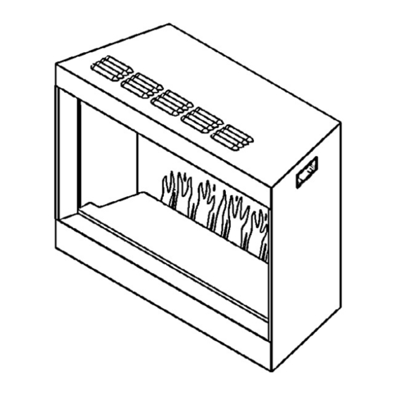
Page 9: Appliance Dimensions
APPLIANCE DIMENSIONS 21-11/16 [550] Vents 6’ (72”) Electrical cord 1/4 [6] with 3-prong grounded plug 27 [685] Vents 1/4 [6] NOTE: Appliance equipped with levelling bolts for installation on uneven Levelling bolts: surface. inch [mm] 3/16 [5] Clearances from combustibles Top: 0 Bottom: 0 Sides: 0... -
Page 10: Accessories
ACCESSORIES LOG SETS This appliance is supplied with black glass embers and vermiculite. In addition, three optional log sets are offered to complement the embers/vermiculite: • GE3DWK—Driftwood Log Kit • GE3BLK—Birch Log Kit • GE3SWK—Splitwood Log Kit... -
Page 11: Trims, Fronts & Backing Plates
TRIMS, FRONTS & BACKING PLATES Optional backing plates and fronts are offered separately to help finish the appliance contour, either when installed in the chimney or framed into the wall. Follow the instructions supplied with each backing plate/front. • GE3CFV—Clearview Front. Requires either GE3SK1 or GE3BPB1. •... -
Page 12: Installation Instructions
INSTALLATION INSTRUCTIONS PREPARATION BEFORE INSTALLATION Tools A screwdriver, a spirit level and drill will be needed. Appliance Location Your new electric fireplace may be installed either in an existing fireplace cavity or framed into the wall. However, when choosing a location, ensure that the general instructions are followed: •... - Page 13 Clean and Insulate Existing Fireplace Cavity A few points must be considered before inserting the GE3 into an existing fireplace cavity including minimum cavity dimensions shown below. • Clean Fireplace and Chimney. Have the chimney swept and the fireplace cavity including ash dumps and clean-outs cleaned before installing the GE3 fireplace.
-
Page 14: Installing Into A Built-In Cavity
Installing into a Built-in Cavity • Prepare the framing. As a general guide only, see picture below. NOTE: Ensure a firm flat positioning of the appliance and secure fixing to avoid vibration and movement of the appliance after finishing. • Wall finish. Hard surfaces can amplify sound. Consider adding some underlay or similar to the inside surface of the wall finish. -
Page 15: Connect The Power Supply
Connect the Power Supply The power connection can be made with the 6 feet Mains Cable provided or alternatively it can be hard wired by unscrewing and removing the Access Plate, the Mains Cable and retention grommet. The access plate can be repositioned so that the 22mm hole sits over the cutout in back of appliance. -
Page 16: Prepare The Appliance
Prepare the Appliance Removing the front glass panel 1. Stick the small magnetic handle to the bottom of one of the appliance’s side panel. The side panels are held in place by magnets. 2. Pull the panel towards the center of the appliance then grab the panel and remove it. - Page 17 5. Using the suction cup (orange) provided to support the middle of the glass panel and lift the panel upwards and pull it forwards as its lower edge. Carefully lift glass away as shown below. 6. Very carefully pull the glass bottom first and then slide down top to disengage it from the top strip.
-
Page 18: Installation
INSTALLATION Slide the fireplace into the cavity of the existing prepared fireplace or into the built-in framing. Plug in the fireplace or hard-wire it. See details under Connect Power Supply in this manual. Check that the power functions. See Operating Instructions section for details. Fuel Bed Once the appliance is in final place, install the fuel bed. -
Page 19: Operating Instructions
OPERATING INSTRUCTIONS BEFORE OPERATION: WARNING! Do not operate the appliance if it is damaged or malfunctions. If you suspect the appliance is damaged or malfunctions, call a qualified service engineer to inspect the appliance, and replace any part of the electrical system if necessary before reusing. -
Page 20: Manual Control
MANUAL CONTROL MANUAL SWITCH Press “I” to turn on the appliance; press “O” to turn it off. STAND-BY Press to turn on the appliance with the last used settings without any heat. Places the appliance into standby mode with all features turned off. FLAME Press repeatedly to cycle through 6 fire preset modes and 3 user defined presets if programmed. -
Page 21: Remote Control
REMOTE CONTROL Timer 0.5h Battery Power ROOM Actual Room T emperature Heating Period T emperature Set NOTE: The remote control handset must be left in the same room as the appliance because it houses the thermostat that regulates heat output. Also, when using the APP, the remote must also be in the same room and have batteries fitted and working to ensure accurate temperature control. - Page 22 MY Flame Press to enter My Flame adjustment screen. Press to select 6 My Flame modes (+3 user defined presets if programmed). There are 3 preset slots allocated for the user to save personalised settings. Simply choose the flame color and brightness level, the fuel color and brightness level.
- Page 23 Timer Mode NOTE: This setting is only for operating in normal mode. It allows the appliance to go into standby after a set period of time. Press to cycle through the settings from 0.5 hour to 10 hours, and then OFF. Adaptive Start Control Learning from the previous heating cycle enables the appliance to judge the appropriate advance time to turn on the heater to ensure that the set...
- Page 24 Resetting the Thermal Cut Out The appliance is fitted with an Electric Safety Control (E.S.). This is a safety device, which switches off the fire if, for any reason, the appliance overheats, e.g. when covered. If the heater stops operating while the flame effect continues working normally, this indicates that the E.S.
-
Page 25: App Control
APP CONTROL Visit your APP store for iOS or Android to download the C&JsmartFIRE APP. Or use the QR code on this page. Follow your devices onscreen instructions to create an account. Once installed, follow the procedure below to pair the device with your appliance. -
Page 26: Maintenance
MAINTENANCE WARNING: Before any maintenance or cleaning of the exterior of the fireplace, the unit should be disconnected from the power supply AND cooled off. ALWAYS turn the heater OFF and unplug the power cord from the outlet before cleaning, performing maintenance, or moving this fireplace. -
Page 27: Service Parts List & Wiring Diagram
SERVICE PARTS LIST & WIRING DIAGRAM Item Part number Master Control Unit (Heater Unit + PCB Unit) 9644 Front Glass Panel 9645 Rear Screen 9646 Downlight Unit 9647 Left Panel Front 9648 Left Panel Rear 9649 Flame Screen 9650 Right Panel Front 9651 Right Panel Rear 9652... - Page 30 Distributed in Canada and USA exclusively by Valor Fireplaces — Head Office #190, 2255 Dollarton Hwy, North Vancouver, BC V7H 3B1 Phone: 604.984.3496 Email: info@valorfireplaces.com Manufactured by Charlton & Jenrick Ltd Unit D, Stafford Park 2, Telford, Shropshire, TF3 3AR, UK. Tel: ++ 44 1952 200 444 Fax ++ 44 1952 200 480 w: www.charltonandjenrick.co.uk e: sales@charltonandjenrick.co.uk...
Need help?
Do you have a question about the Valor GE3 and is the answer not in the manual?
Questions and answers