Table of Contents
Advertisement
Quick Links
Instructions - Repair - Parts
Check-Mate
Series Displacement
Pumps
Pump with priming piston and Elite Series rod and cylinder. For professional use only.
Model L100CE (Series B), L200CE(Series B), L250CE and L500CE
See page 3 for model information. See page 43 for Maximum Working Pressure.
Important Safety Instructions
Read all warnings and instructions in this
manual before using the equipment.
Save these instructions.
Model L100CE
Series B
®
Elite
Model L200CE
Series B
Model L250CE
3A8564D
Model L500CE
EN
Advertisement
Table of Contents

Related Manuals for Graco Check-Mate Elite Series


Summary of Contents for Graco Check-Mate Elite Series
- Page 1 Instructions - Repair - Parts ® Check-Mate Elite Series Displacement Pumps 3A8564D Pump with priming piston and Elite Series rod and cylinder. For professional use only. Model L100CE (Series B), L200CE(Series B), L250CE and L500CE See page 3 for model information. See page 43 for Maximum Working Pressure. Important Safety Instructions Read all warnings and instructions in this manual before using the equipment.
-
Page 2: Table Of Contents
Technical Specifications ....43 Graco Standard Warranty ....44... -
Page 3: Models
Models Models Check your displacement pump’s identification plate (ID) for the 6-digit part number of your displacement pump. Use the following matrix to define the construction of your displacement pump, based on the six digits. For example, displacement pump Part No. L100CE represents the displacement pump (L), output volume in cc per cycle (100), carbon steel construction (C), and Elite series (E). -
Page 4: Warnings
Warnings Warnings The following warnings are for the setup, use, grounding, maintenance, and repair of this equipment. The exclamation point symbol alerts you to a general warning and the hazard symbols refer to procedure-specific risks. When these symbols appear in the body of this manual or on warning labels, refer back to these Warnings. Product-specific hazard symbols and warnings not covered in this section may appear throughout the body of this manual where applicable. - Page 5 Warnings WARNING FIRE AND EXPLOSION HAZARD Flammable fumes, such as solvent and paint fumes, in work area can ignite or explode. Paint or solvent flowing through the equipment can cause static sparking. To help prevent fire and explosion: • Use equipment only in well-ventilated area. •...
- Page 6 Warnings WARNING TOXIC FLUID OR FUMES HAZARD Toxic fluids or fumes can cause serious injury or death if splashed in the eyes or on skin, inhaled or swallowed. • Read Safety Data Sheets (SDSs) for handling instructions and to know the specific hazards of the fluids you are using, including the effects of long-term exposure.
-
Page 7: Manuals
Important Isocyanate (ISO) Information Important Isocyanate (ISO) Information Isocyanates (ISO) are catalysts used in two component materials. Isocyanate Conditions NOTICE Partially cured ISO will reduce performance and the life of all wetted parts. • Always use a sealed container with a desiccant Spraying or dispensing fluids that contain dryer in the vent, or a nitrogen atmosphere. -
Page 8: Component Identification
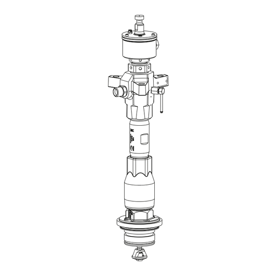
Component Identification Component Identification Model L100CE Model L200CE Series B Series B Model L250CE Model L500CE . 2: Key: Displacement Rod Intake Valve Housing Wet Cup Intake Cylinder Throat Packing Cartridge Priming Piston Assembly Outlet Housing Wet Cup Sight Glass Fluid Outlet Wet Cup Fill Cap * Not shown in the drawing... -
Page 9: Operation
Operation Operation Pressure Relief Procedure 3. For L20c Air Controls: See F . 4. Follow the Pressure Relief Procedure a. Close the bleed type air motor valve and the whenever you see this symbol. elevator director valve. The ram will slowly drop. -
Page 10: Recycling And Disposal
Recycling and Disposal Recycling and Disposal End of Product Life At the end of the product’s useful life, dismantle and recycle it in a responsible manner. • Perform the Pressure Relief Procedure page 9. • Drain and dispose of fluids according to applicable regulations. -
Page 11: Troubleshooting
Troubleshooting Troubleshooting 1. Follow Pressure Relief Procedure, page 9. 2. Check all possible problems and causes before disassembling pump. Problem Cause Solution Pump fails to operate. Restricted line or inadequate air Clear; increase air supply. Ensure supply; closed or clogged valves. that all valves are open. - Page 12 Troubleshooting Problem Cause Solution Erratic or accelerated pump speed. Exhausted fluid supply. Refill and prime. Fluid is too heavy for pump priming. Use drain/purge valve. Use a ram. See Supply Units Operation manual 313526. Increase ram air pressure. Held open or worn intake valve or Clear valve.
-
Page 13: Repair
Repair Repair Required Tools 7. Use packing nut wrench (supplied) to loosen and remove packing nut/enclosed wet cup (144). • Torque wrench • Bench vise, with soft jaws • Rubber mallet • Hammer • 400 mm (15.8 in.) adjustable wrench •... -
Page 14: Disassembly
Repair 12. Torque cartridge (143) to specified torque listed in 4. Use packing nut wrench (supplied) to loosen and the following table. remove packing nut/enclosed wet cup (144). Displacement Pump Torque 100cc 90-130 ft-lbs (122-173 N•m) 200cc and 250cc 130-190 ft-lbs (176-258 N•m) 500cc 149-261 ft-lbs (203-355 N•m) 13. - Page 15 Repair NOTE: Steps 7-13 apply to 100cc, 200cc, and 250cc 9. Use an adjustable wrench to unscrew intake valve displacement pumps only. housing (117) from cylinder (116) and outlet housing (109). Pull intake valve housing off cylinder. Intake 7. Push on the upper displacement rod (118) to check valve assembly (126/127/128) should slide expose flats of the lower shaft assembly (125).
- Page 16 Repair 11. Use an o-ring pick to remove seal (130) from intake NOTE: Steps 14-20 apply to 500cc displacement valve housing (117). Discard seal; use a new one for pumps only. reassembly. See F . 14. 14. Hold flats of the priming piston rod (420) with an 12.
- Page 17 Repair 16. Tap underside of outlet housing (402) with a rubber 21. Examine mating surfaces of seat (129) and intake mallet to loosen housing from cylinder (414). Lift valve body (128) for damage. outlet housing off displacement pump and set it aside.
- Page 18 Repair NOTE: Steps 24-25 apply to 100cc and 200cc dis- NOTE: Steps 26-27 apply to 250cc and 500cc dis- placement pumps only. placement pumps only. 24. Place flats of the upper displacement rod (118) in a 26. Place flats of displacement rod (401) in a vise. bench vise.
-
Page 19: Reassembly
Repair Reassembly 28. Place piston seat (123) and guide (121) in vise. Slide a brass rod through openings in piston guide and unscrew it from seat. Remove piston seal (122) and NOTE: All individual parts being reused from any guide bearing (120). disassembly must be thoroughly cleaned in a compatible solvent and inspected for damage. - Page 20 Repair 4. Place the second lower shaft seal (127) face up into NOTE: Steps 7-10 apply to 200cc displacement pumps the seal guide tool (135). Insert the lower shaft seal only. using the larger face side of the seal insertion tool (134), or a suitable size socket or dowel.
- Page 21 Repair NOTE: Steps 11-13 apply to 250cc and 500cc 14. Lubricate piston seal (122) and install it on piston displacement pumps only. seat (123). Screw piston guide (121) onto seat (123). Place piston seat in a vise and use a brass 11.
- Page 22 Repair NOTE: Step 16 apply to 100cc and 200cc displace- NOTE: Step 17 apply to 250cc and 500cc displace- ment pumps only. ment pumps only. 16. Place the flats of the upper displacement rod (118) 17. Place flats of displacement rod (401) in a vise. into a bench vise.
- Page 23 Repair NOTE: Steps 18- 23 apply to 100cc, 200cc, and 250cc 20. Lubricate o-ring (105) and install it on the bottom of displacement pumps only. cylinder (116). Slide intake valve housing (117) onto priming piston rod (125). Ensure smooth surface of 18.
- Page 24 Repair 23. Lubricate threads of intake cylinder (131). Use an NOTE: Steps 24-31 apply to 500cc displacement adjustable wrench to screw intake cylinder into pumps only. intake valve housing (117). Torque intake cylinder; see the following table for correct torque. This will 24.
- Page 25 Repair 30. Put intake housing (418) upright in a vise, making 32. Lubricate throat seal (145), and install it in throat sure it is off-center so there is a sufficient clearance cartridge (143). for priming piston rod (420) to be lowered through housing.
- Page 26 Repair 34. Use packing nut wrench (supplied) to tighten wet 36. Install new o-ring (149), wet cup wiper (148), seal cup (144) to specified torque; refer to the following (147), and snap ring (146) into wet cup cover (153). table. See F .
- Page 27 Repair 38. Check that flats of priming piston rod (125) are NOTE: Step 40 apply to 500cc displacement pumps accessible below intake cylinder (131). If not, tap on only. top of displacement rod (118) with a rubber mallet until flats are exposed. 40.
-
Page 28: Parts
Parts Parts 100 cc Displacement Pump L100CE Series B Series A 139/140 142/140 N•m Torque to 53 ft-lbs (72 N•m Torque to 110 ft-lbs (149 N•m Torque to 250 ft-lbs (339 N•m Torque to 10 ft-lbs (14 Apply thread sealant N•m Torque to 30 ft-lbs (41 Apply anti-seize to threads... - Page 29 Parts 100 cc Displacement Pump L100CE Assembly Parts List Kit Number Series A to Series Series A and B Shared Series B Series B A Kit Kits Kits Upgrade Kit Kit No. and Part Ref. Description ----- FITTING, grease, M5 SCREW, SHS, EXT tip, ----- M5x8...
- Page 30 Parts Kit Number Series A to Series Series A and B Shared Series B Series B A Kit Kits Kits Upgrade Kit Kit No. and Part Ref. Description RING, retaining, int, 0.875 Kit #2/#3 in. OD SEAL, shaft, lower, CM100 Kit #2 VALVE, check, in, poppet, Kit #3...
- Page 31 Parts Kit Number Series A to Series Series A and B Shared Series B Series B A Kit Kits Kits Upgrade Kit Kit No. and Part Ref. Description Kit #13/#14 SIGHTGLASS Kit #13/#14 COVER, oil hole Kit #13/#14 SCREW, shcs M5 X 12 Kit #13/#14 COVER, wet cup, cm100 Kit #13/#14...
-
Page 32: 200 Cc Displacement Pump L200Ce
Parts 200 cc Displacement Pump L200CE Series B Series A 230/231 N•m Torque to 97 ft-lbs (132 N•m Torque to 60 ft-lbs (81 N•m Torque to 390 ft-lbs (529 N•m Torque to 10 ft-lbs (14 230/231 N•m Torque to 255 ft-lbs (346 N•m Torque to 30 ft-lbs (34 Apply thread sealant... - Page 33 Parts 200 cc Displacement Pump L200CE Assembly Parts List Kit Number Series A to Series Series A and B Shared Series B Series B A Kit Kits Kits Upgrade Kit Kit No. and Part Ref. Description ----- FITTING, grease, M5 SCREW, SHS, EXT tip, ----- M5x8...
- Page 34 Parts Kit Number Series A to Series Series A and B Shared Series B Series B A Kit Kits Kits Upgrade Kit Kit No. and Part Ref. Description SPACER, seal, lower, Kit #3 CM200, XL SEAL, shaft, lower, Kit #2 CM200, XL VALVE, check, in, poppet, Kit #3...
- Page 35 Parts Upper shaft seal (203) can not be ordered anymore, please order throat seal (244) instead of it ▲ Replacement safety labels, tags, cards are available at no cost. ✓ Not shown. O-ring kit, 26B931 Rod Seals and Piston Kit, 2005348 Inlet Check Kit, 26B934 Outlet Check Kit, 26B935 Upper Rod Kit, 26B936...
-
Page 36: 250 Cc Displacement Pump L250Ce
Parts 250 cc Displacement Pump L250CE 336/337 336/337 337/340 Torque to 239-271 ft-lb (323-366 N•m) Torque to 95-115 ft-lb (128-155 N•m) Torque to 345-435 ft-lb (466-587 N•m) Torque to 71-79 ft-lb (96-107 N•m) Torque to 92-102 ft-lb (124-138 N•m) Torque to 57-63 ft-lb (77-85 N•m) Torque to 130-190 ft-lb (176-258 N•m) Apply thread sealant Lubricate all soft seal components before installation. - Page 37 Parts 250 cc Displacement Pump L250CE Assembly Parts List Kit Number Kit No. and Part Ref. Description UPPER ROD, Kit #5 displacement; ceramic OUTLET HOUSING ---- Cartridge Kit #7 O-RING Kit #1/#2/#7 UPPER SEAL, vee and Kit #2 U-cup, L250CE Kit #4 COVER, wet cup Kit #4...
- Page 38 Parts Kit Number Kit No. and Part Ref. Description LOWER SEAL, vee and Kit #3/#10 U-cup, L250CE SEAL, valve Kit #3/#10 HOUSING, valve Kit #14 PLUG, valve Kit #14 HANDLE, outlet bleed Kit #14 CLIP, outlet bleed Kit #14 Kit #12 184090▲ LABEL, warning SCREW, drive Kit #12 100508 TAG, instruction, safety...
-
Page 39: 500 Cc Displacement Pump L500Ce
Parts 500 cc Displacement Pump L500CE Torque to 327-363 ft-lb (441-490 N•m) Torque to 95-115 ft-lb (128-155 N•m) 440/443 Torque to 90-100 ft-lb (122-135 N•m) Torque to 71-78 ft-lb (96-106 N•m) Torque to 149-261 ft-lb (203-355 N•m) Torque to 160-220 ft-lb (217-299 N•m) Torque to 104-136 ft-lb (141-185 N•m) 436 7 Apply thread sealant... - Page 40 Parts 500 cc Displacement Pump L500CE Assembly Parts List Kit Number Kit No. and Part Ref. Description UPPER ROD, Kit #1 displacement; chrome OUTLET HOUSING Kit #12 Cartridge Kit #2 O-RING Kit #2/#9/#11 UPPER SEAL, vee and Kit #9 U-cup, L500CE Kit #3 COVER, wet cup Kit #3...
- Page 41 Parts Kit Number Kit No. and Part Ref. Description HOUSING, valve Kit #14 PLUG, valve Kit #14 HANDLE, outlet bleed Kit #14 CLIP, outlet bleed Kit #14 FITTING, outlet 184279 Kit #11/#12 SEAL, outlet 109213 BOLT, hex 109203 Kit #12 184293▲ LABEL, warning SCREW, drive Kit #12 100508 TAG, instruction, safety...
-
Page 42: Dimensions
Dimensions Dimensions L100CM L200CM L250CM L500CM . 47 Displacement (Outlet Housing Mounting (Height) (Outlet Size) Pump Hole Diameter) in. (mm) in. npt in. (mm) 100cc 28.62 (727.0) 3/4 npt(m) 5.91 (150.0) 200cc 29.75 (755.7) 1 npt(f) 8.0 (203.0) 250cc 29.68 (754.0) 1 npt(f) 8.0 (203.0) 500cc... -
Page 43: Technical Specifications
Technical Specifications Technical Specifications ® Check-Mate Elite Series Displacement Pumps Metric Maximum operating temperature 180 °F 80 °C Maximum fluid working pressure 100cc 4200 psi 28.9 MPa, 289.6 bar 200cc 4200 psi 28.9 MPa, 289.6 bar 250cc 6200 psi 43.4 MPa, 434 bar 500cc 3900 psi 27.3 MPa, 273 bar... -
Page 44: Graco Standard Warranty
With the exception of any special, extended, or limited warranty published by Graco, Graco will, for a period of twelve months from the date of sale, repair or replace any part of the equipment determined by Graco to be defective.
Need help?
Do you have a question about the Check-Mate Elite Series and is the answer not in the manual?
Questions and answers