Table of Contents
Advertisement
Quick Links
Advertisement
Table of Contents

Related Manuals for Hach LANGE ULTRATURB sc


Summary of Contents for Hach LANGE ULTRATURB sc
- Page 1 客服:400 688 9809...
- Page 2 客服:400 688 9809 DOC023.52.03231.Oct03 ULTRATURB sc ULTRATURB plus sc Operating instructions...
- Page 3 客服:400 688 9809 © LANGE Group, 2003. All rights reserved. Printed in Germany...
- Page 4 客服:400 688 9809 DOC023.52.03231.Oct03 ULTRATURB sc ULTRATURB plus sc Operating instructions © LANGE Group, 2003. All rights reserved. Printed in Germany...
- Page 5 客服:400 688 9809...
-
Page 6: Table Of Contents
客服:400 688 9809 Contents Section 1 Technical data............................... 3 Section 2 General information ............................. 5 2.1 Applications ................................5 2.2 Measuring principle ..............................5 2.3 Handling ..................................5 2.4 Items supplied ................................6 2.5 Function check ................................7 Section 3 Installation..............................8 3.1 Mechanical installation .............................. - Page 7 客服:400 688 9809 Contents 6.4 Replacing desiccant ..............................53 6.5 Monitoring test equipment............................53 6.5.1 Preparing formazine solution in accordance with DIN EN ISO 7027..............54 6.6 Changing fuses ................................55 Section 7 Faults, causes, rectification ........................56 7.1 Error messages................................56 7.2 Warnings ..................................56 7.3 Wrong passcode? ..............................56 Section 8 Spare parts ..............................57 Section 9 Warranty and liability..........................58 Section 10 Contact...............................59...
-
Page 8: Section 1 Technical Data
客服:400 688 9809 Section 1 Technical data Table 1-1 ULTRATURB sc and plus microprocessor-controlled turbidity bypass sensor ULTRATURB sc for Components: very low to medium turbidities with comprehensive self-diagnostics Measuring technique: 90° infrared pulse scattered light technique in accordance with DIN EN ISO 7027 0.0001-1000 FNU (TE/F, NTU, FTU) can be programmed as required Measuring range: (0.0001-250 EBC = 2500 ppm SiO2) - Page 9 客服:400 688 9809 Technical data Table 1-2 sc100 controller microprocessor-based controller with measured value indication, temperature display Components: and menu-based operation. -20 to 60 °C; 95 % relative humidity, non-condensing, sensor cable <7 W; -20 to 40° C Ambient temperature controller: at sensor power <25 W Storage temperature: -20 to 70 °C;...
-
Page 10: Section 2 General Information
客服:400 688 9809 Section 2 General information 2.1 Applications ULTRATURB sc bypass sensors are innovative precision turbidity measuring instruments developed using the latest technical findings. Turbidities in the range of FNU (NTU) 0.0001-1000 are measured and displayed alphanumerically using a controller. -
Page 11: Items Supplied
客服:400 688 9809 General information 2.4 Items supplied ULTRATURB sc sensor Factory test certificate sc100 controller Accessory set LZP816 Connecting cable (length as per order) Wiper set (for 4 changes) LZV275 (only plus version) Operating instructions... -
Page 12: Function Check
客服:400 688 9809 General information 2.5 Function check After unpacking, both components should be checked for any transport damage and a short function check performed prior to installation. For this purpose the sensor is connected to the display unit and the display unit plugged into the mains. -
Page 13: Section 3 Installation
客服:400 688 9809 Section 3 Installation 3.1 Mechanical installation Note: This system is only allowed to be installed by qualified personnel! Fig. 3-1 Installation overview Mains connection Connecting cable sc100 controller Mains cable ULTRATURB sc sensor... - Page 14 客服:400 688 9809 Installation Fig. 3-2 sc100 controller components Controller Oval-head bolt (4), M6 x 18 mm Fastening lug (2x) for switch panel installation Oval-head bolt (4), M6 x 100 mm Clip for switch panel installation or mounting on vertical or Washer (4) horizontal pipe profiles Rubber seal for switch panel installation...
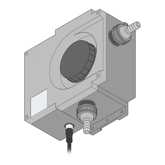
- Page 15 客服:400 688 9809 Installation Fig. 3-3 Instrument layout ULTRATURB sc Sensor cable socket Hose nipple* Wiper holder (only plus version) Diaphragm plate* (if necessary) Measuring chamber sealing plug O-ring* Screw top 10. Union (pre-assembled) Waste 11. Sealing ring (pre-assembled) Union nut* 12.
-
Page 16: Fastening Controller
客服:400 688 9809 Installation 3.2 Fastening controller 3.2.1 Dimensions of the controller Fig. 3-4 Housing dimensions Fig. 3-5 Dimensions for fastening 144.02 mm (5.67 inches) 72.01 mm (2.84 inches) 72.01 mm (2.84 inches) 40.14 mm (1.58 inches) 80.27 mm (3.16 inches) 144.02 mm (5.67 inches) M6 x 1.0... - Page 17 客服:400 688 9809 Installation Fig. 3-6 Cut-out for switch panel installation 144 mm 5.67 inches (ref only) 72 mm 2.955 inches (ref only) 144 mm 135 mm 5.67 inches 5.31 inches (ref only) 72 mm 69 mm 2.955 inches 2.7 inches (ref only) 65 mm 2.575 inches 133 mm 5.25 inches...
-
Page 18: Fastening Controller
客服:400 688 9809 Installation 3.2.2 Fastening controller Fastening the controller to railings, wall or in a switch panel. The material for fastening the controller is shown in Fig. 3-8 to 3-10. Fig. 3-8 Vertical or horizontal fastening to pipe profiles Controller Washer (4) Pipe profile (vertical or horizontal) - Page 19 客服:400 688 9809 Installation Fig. 3-10 Switch panel installation Controller Oval-head bolt M6 x 1.0 x 20 mm (4) Rubber seal for switch panel installation Hex nut M6 x 1.0 (4) Switch panel, max. 9.5 mm thick Washer (4) Clip (2x) for switch panel installation Oval-head bolt M6 x 1.0 x 150 mm (4) Clip for fastening the controller 10.
- Page 20 客服:400 688 9809 Installation Fig. 3-11 Internal wiring of the sensor Wire colour Input No. Blue White No connection Brown Black Screen grey...
-
Page 21: Electrical Installation
客服:400 688 9809 Installation Electrical installation For safety reasons the connections for the power supply are underneath a Note: This system is only allowed to be installed by qualified protective cover. This cover is only allowed to be removed by qualified personnel personnel. - Page 22 客服:400 688 9809 Installation Fig. 3-13 Fitting the cable feed entries Cable gland Conduit gland Water-proof blanking plugs Fig. 3-14 Stripping insulation from the cable and connection of the cable Remove 6 mm of insulation Push the stripped end of the cable fully home. (it is recommended to fit ferrules).
-
Page 23: Connecting Power Supply
客服:400 688 9809 Installation 3.3.3 Connecting power supply You can connect the controller to the power supply using either a mains cable or Note: If the plug is removed from the mains plug and replaced with using hard wiring (if necessary using conduit). The connection is made hard wiring, then a suitable, independent of the cable type and always to the same terminals. - Page 24 客服:400 688 9809 Installation Fig. 3-15 Cable connections NETWORK INTERFACE RELAY A RELAY B RELAY C RELAY C CARD Connection for external network Sensor connection 1 Connection for optional network card Sensor connection 2 Connection relay A 10. J6 connection current outputs Connection relay B 11.
- Page 25 客服:400 688 9809 Installation Fig. 3-16 Interruption of the power supply with mains cable NETWORK INTERFACE RELAY A RELAY B RELAY C CARD Terminals for mains connection Cable gland for main cable Fig. 3-17 2-pole isolation of the power supply with hard wiring NETWORK INTERFACE RELAY A...
- Page 26 客服:400 688 9809 Installation Relay contacts The controller has 3 floating relay contacts for up to max. 250 V AC, 50-60 Hz, 5 A or max. 30 V DC, 5 A. The operation of the relay contacts is described in Sec. 5.8. 3.4.1 Connecting relay contacts The terminals for the relay changeover contacts are designed for cable cross- Note: All information on relay...
-
Page 27: Connecting Current Outputs
客服:400 688 9809 Installation 3.4.2 Connecting current outputs The controller has two separate current outputs (1 and 2). The two current outputs Note: Only use screened cable for the current outputs to exclude the (0/4-20 mA, max. 500 Ohm) transmit one or both measured values depending on possibility of external the setting in the program. -
Page 28: Connecting Sensor Cable
客服:400 688 9809 Installation 3.5 Connecting sensor cable You can connect the sensor cable to the controller very easily using the plug. Retain the protective cap for the socket in case you need to remove the sensor in the future. Connecting cables are available in the lengths 5 m, 10 m, 15 m, 20 m, 30 m and 50 m (see list of spare parts). - Page 29 客服:400 688 9809 Installation Wire colour Input No. Blue White No connection Brown Black Screen grey Fig. 3-22 Direct wiring of the sensor Table 3-4 Terminal assignments J5 and cable colours Terminal No. Terminal assignments Cable colour A (+) Blue B (-) White Service request...
-
Page 30: Termination Box
客服:400 688 9809 Installation 3.6 Termination box If the distance between the sensor and the controller is greater than 100 m, a termination box must be integrated into the connecting cable. If two sensors are connected, two termination boxes are required as soon as this distance of 100 m is exceeded for at least one sensor. - Page 31 客服:400 688 9809 Installation Fig. 3-24 Termination box connection terminals Screen (grey) Not used Ground (black) +12 V DC (brown) Data cable - (white) Pre-assembled in the factory Not used Sensor connecting cable Data cable + (blue) 10. Connecting cable to the controller...
-
Page 32: Connecting Digital Interface (Optional)
客服:400 688 9809 Installation 3.7 Connecting digital interface (optional) Currently the manufacturer supports ModBUS RS485 and ProfiBUS. The position for the optional network card is shown in Fig. 3-25. The connecting terminals for the user are on terminal strip J1. The connections vary depending on the bus system. -
Page 33: Section 4 Commissioning
客服:400 688 9809 Section 4 Commissioning 4.1 Commissioning 1. Insert the plug on the end of the sensor cable in the related socket in the controller. 2. Plug into the mains plug or switch on the power supply. 3. When the controller is switched on for the first time, a menu for selecting the language opens automatically. -
Page 34: Section 5 Operation
客服:400 688 9809 Section 5 Operation 5.1 Using the keypad At the top on the front of the controller is the display, and underneath the display the keypad with 8 keys; the function of the keys is explained in Table 5-6. Fig. -
Page 35: Controller Display
客服:400 688 9809 Operation 5.2 Controller display The controller display indicates the current turbidity value during measurements if a sensor is connected. The display flashes on commissioning if • A sensor fault occurs • The "HOLD OUTPUTS" function has been activated An active system warning results in the display of a warning icon on the right of the display (a triangle with an exclamation mark in the middle). -
Page 36: Setting Display Contrast
客服:400 688 9809 Operation 5.2.1 Setting display contrast Select Menu level Accept MAIN MENU SYSTEM SETUP DISPLAY SETUP ADJ. CONTRAST (+ 0-50) MAIN MENU or Indication of measurement 5.2.2 Selecting language Select Menu level Accept MAIN MENU SYSTEM SETUP DISPLAY SETUP LANGUAGE Select language from list MAIN MENU or... -
Page 37: Setting Date And Time
客服:400 688 9809 Operation 5.2.3 Setting date and time 5.2.3.1 Setting time Select Menu level Accept MAIN MENU SYSTEM SETUP DISPLAY SETUP SET DATE/TIME Mark TIME Select character Set time MAIN MENU or Indication of measurement 5.2.3.2 Setting date Select Menu level Accept MAIN MENU... -
Page 38: System Configuration
客服:400 688 9809 Operation 5.3 System configuration Select Menu level Accept MAIN MENU SENSOR-SETUP SELECT SENSOR CONFIGURATION LOCATION Select character Move to next position Complete system configuration by setting the following menu items: MEAS UNIT CLEANING RESPONSE TIME LOGGERINTERV. RESOLUTION SET DEFAULTS MAIN MENU or Indication of measurement... -
Page 39: Setting Up Passcode Protection
客服:400 688 9809 Operation 5.3.1 Setting up passcode protection The sc100 controller has a security feature to prevent unauthorised access to configuration and calibration settings. The default passcode from the factory is sc100_ (five characters plus space). Section 5.3.1.1 describes how you can change the passcode. ACTIVATE: All setting in the CONFIGURATION menu are displayed, but cannot be changed. - Page 40 客服:400 688 9809 Operation 5.3.1.1 Changing passcode When you have activated the passcode, you can also change it. The passcode used may have up to 6 characters (along with letters and numbers, other characters are also available). However as soon as you select the SET DEFAULTS menu command on the CONFIGURATION menu, the default setting from the factory for the passcode is also re-applied.
-
Page 41: Calibration With Standard Solution
客服:400 688 9809 Operation 5.4 Calibration with standard solution Select Menu level Accept MAIN MENU SENSOR-SETUP SELECT SENSOR (if there is more than one sensor) CALIBRATION STANDARD OUTPUT MODE information TURN OFF SAMPLE INLET DRAIN MEAS.CHAMBER (via the lower feed union) POUR STD INTO MEAS.CHAMBER... -
Page 42: Verify Using Dry Standard Cvm
客服:400 688 9809 Operation 5.5 Verify using dry standard CVM Select Menu level Accept MAIN MENU SENSOR-SETUP SELECT SENSOR (if there is more than one sensor) VERIFY STANDARD OUTPUT MODE information TURN OFF SAMPLE INLET DRAIN MEAS.CHAMBER (via the lower feed union, then dry carefully) INSERT CVM STANDARD (For this purpose open measuring chamber,... -
Page 43: Zero Point Setting
客服:400 688 9809 Operation 5.6 Zero point setting Select Menu level Accept MAIN MENU SENSOR-SETUP SELECT SENSOR (if there is more than one sensor) CALIBRATION OFFSET OUTPUT MODE information POUR 0 SANDARD INTO MEAS.CHAMBER (Dry measuring chamber and use filter set for zero point calibration LZV325) PRESS ENTER WHEN CONSTANT... -
Page 44: Output Signals
客服:400 688 9809 Operation 5.7 Output signals The controller has two independent analogue current outputs (current output 1 and current output 2). The following table provides an overview of all possible settings to suit your requirements. SYSTEM SETUP OUTPUT SETUP SELECT OUTPUT 1 or 2 SELECT Using the Enter key open a list with all the sensors connected and choose the sensor with the... -
Page 45: Holding Outputs / Substitute Values
客服:400 688 9809 Operation 5.7.1 Holding outputs / substitute values The analogue current outputs can also retain the last measured values during normal measurement operation. Proceed as follows to hold the current outputs until another command is issued: Select Menu level Accept MAIN MENU TEST/MAINT... -
Page 46: Relay Settings
客服:400 688 9809 Operation 5.8 Relay settings 1. Press ENTER to open the Main menu. 2. Mark SYSTEM SETUP and press ENTER. 3. Mark RELAY and press ENTER. Make the relay settings with the aid of the following table: RELAY SELECT RELAY A, B or C SELECT SOURCE Choose one of the sensors listed or RTC (timer) -
Page 47: Data Logger Options
客服:400 688 9809 Operation OFF DELAY Time delay (0-300 seconds) before the relay is normally switched off. ON DELAY Time delay (0-300 seconds) before the relay is normally switched on. AS TIMER With the setting ”HIGH” the relay reacts to increasing measured values; PHASE conversely, with ”LOW”... -
Page 48: Digital Network Options
客服:400 688 9809 Operation 5.10 Digital network options The sc100 is equipped with two digital ports, one digital network interface and one infrared interface. Each of the two digital ports provides access to setup data, measured data and the data/event archives. Please see the related documentation for detailed information on these interfaces. -
Page 49: Sensor-Setup
客服:400 688 9809 Operation 5.11.2 SENSOR-SETUP MAIN MENU SELECT SENSOR DIAG DIAG TEST/MAINT WIPE Initiates a wiping action Verification using CVM VERIFY Verification with dry standard module CALIBRATION Selection as per Calibration with standard Procedure during calibration, menu STANDARD CAL.CONFIG OUTPUT solution based MODE... - Page 50 客服:400 688 9809 Operation DIAG/TEST ULTRATURBsc Instrument name LOCATION SERIAL NUMBER PROBE INFO RANGE 0.001 ... 1000 FNU MODEL NUMBER Article no. sensor CODE VERSION DRIVER VERS CAL. DATE FACTOR Default setting 1.00 CAL. DATA Default setting 0.000 OFFSET TRBFNU TOTAL TIME COUNTER WIPER PROFILE...
-
Page 51: System Setup
客服:400 688 9809 Operation 5.11.3 SYSTEM SETUP MAIN MENU OUTPUT SETUP DIAG RELAY NETWORK SETUP TEST/MAINT DISPLAY SETUP OUTPUT SETUP SELECT OUTPUT 1 or 2 NONE Selection of the sensor with the SELECT SOURCE SENSOR1 signals (measured values) accessed: SENSOR2 PARAMETER TURBIDITY LINEAR... - Page 52 客服:400 688 9809 Operation NETWORK SETUP MODBUS ADDRESS BAUD RATE STOP BITS MODBUS MODE DATA ORDER DISPLAY SETUP ADJ. CONTRAST Adjustable from 0 to 50 Can be set to English, Deutsch, LANGUAGE Espanol, Francais, Italiano, Nederlands, Svenska DATE FORMAT SET DATE/TIME DATE TIME SECURITY SETUP...
-
Page 53: Test/Maint
客服:400 688 9809 Operation 5.11.4 TEST/MAINT TEST/MAINT MAIN MENU DIAG CAL. OUTPUTS CAL. OUTPUTS CAL. OUTPUTS CAL. OUTPUTS HOLD OUTPUTS TEST/MAINT OVERFEED RESET STATUS SENSOR1 Status message SENSOR2 Status message RELAY A ACTIVE/INACTIVE RELAY B ACTIVE/INACTIVE RELAY C ACTIVE/INACTIVE CAL. OUTPUTS Disconnect cables, then connect OUTPUT1 CAL 4 mA or 20 mA... - Page 54 客服:400 688 9809 Operation SENSOR1 Selection of the sensor with the SELECT SOURCE signals (measured values) accessed. SENSOR2 PARAMETER TURBIDITY SET SIM VALUE Simulation value for test purposes. SCAN SENSORS ARE YOU SURE? Scans the sensors connected. MODBUS STATS NETWORK PORT Display of the statistics on SENSOR PORT communication (event list) with an...
-
Page 55: Section 6 Maintenance
客服:400 688 9809 Section 6 Maintenance It has been possible to reduce the scope of the maintenance to be performed by the user to only a few actions. Clearly summarised in a table and described in detail in the following sections, these actions can be quickly and straightforwardly performed by qualified personnel. - Page 56 客服:400 688 9809 Maintenance OUTPUT MODE information TURN OFF SAMPLE INLET DRAIN MEAS.CHAMBER (via the lower feed union) OPEN MEAS.CHAMBER REMOVE WIPER HOLDER* CLEAN MEAS.CHAMBER REPLACE WIPER HOLDER* CLOSE MEAS.CHAMBER OPEN SAMPLE INLET (Automatic wiping action after confirmation) *Only on plus version...
-
Page 57: Replacing Wiper Profiles (Only Plus Version)
客服:400 688 9809 Maintenance 6.3 Replacing wiper profiles (only plus version) The life of the wiper profiles is, on the one hand, dependent on the number of cleaning actions performed, and is also dependent on the type of deposits to be removed. -
Page 58: Replacing Desiccant
客服:400 688 9809 Maintenance 6.4 Replacing desiccant The ULTRATURB sc turbidity sensor is continuously subject to a wet environment. To provide protection against the moisture, there are 2 generously sized desiccant bags close to the optical and electronic components. To maintain this protection, the manufacturer recommends replacement or regeneration every 2 years. -
Page 59: Preparing Formazine Solution In Accordance With Din En Iso 7027
客服:400 688 9809 Maintenance Note: If there are any variations in the measurements, it is recommendable to measure a new standard preparation prior to changing the instrument calibration! Experience has shown that the variation in the formazine preparation can be greater than the possible drift in the ULTRATURB instrument. -
Page 60: Changing Fuses
客服:400 688 9809 Maintenance Changing fuses In the controller there are 2 fuses that the user can change. Faulty fuses are indicative of problematic ambient conditions. Only qualified personnel should determine the cause and change the fuse. Figure 6-28 shows the exact position of the fuses that you can change as follows: 1. -
Page 61: Section 7 Faults, Causes, Rectification
客服:400 688 9809 Section 7 Faults, causes, rectification 7.1 Error messages In the case of an error, the indication of the measured value flashes on the display and all the contacts and current outputs allocated to this sensor are place on hold. The following conditions will result in flashing measured values: •... -
Page 62: Section 8 Spare Parts
客服:400 688 9809 Section 8 Spare parts sc100 universal controller (no BUS connections), with mains cable ..........LXV401.99.20001 sc100 universal controller (with MODBUS), with mains cable............LXV401.99.22001 sc100 universal controller (ProfiBUS DP), with mains cable ............LXV401.99.23001 ULTRATURB sc turbidity bypass sensor ..................LPV415.99.01001 ULTRATURB sc turbidity bypass sensor with 0.35 m cable ............ -
Page 63: Section 9 Warranty And Liability
客服:400 688 9809 Section 9 Warranty and liability The manufacturer warrants that the product supplied is free of material and manufacturing defects and undertakes the obligation to repair or replace any defective parts at zero cost. The warranty period is 24 months from the delivery date and can be extended to 5 years by taking out a service contract. -
Page 64: Section 10 Contact
客服:400 688 9809 Section 10 Contact 10.1 Addresses DR. BRUNO LANGE LANGE UK LTD GMBH & CO. KG Lennox Road Willstätterstraße 11 Basingstoke D-40549 Düsseldorf Hampshire, RG22 4AP Tel. +49 (0)211-5288-0 Tel. +44 (0)1256 333 403 Fax +49 (0)211-5288-143 Fax +44 (0)1256 330 724 kundenservice@drlange.de info@drlange.co.uk www.drlange.de... - Page 65 客服:400 688 9809 Appendix A ModBUS Register Information Table A-8 Controller ModBUS Registers Group Name Tag Name Register # Data Type Length Description Calculated Value calculated from two sensor Measurements 40001 Float Value measurements Unsigned Setup Language 40003 Current System Language Integer Current Data Display Format Unsigned...
- Page 66 客服:400 688 9809 ModBUS Register Information Table A-8 Controller ModBUS Registers (continued) Group Name Tag Name Register # Data Type Length Description Unsigned Selects output type (0 = Linear output; Setup/Analog Output 2 Type 40031 Integer 1 = PID control) Setup/Analog Output 2 Transfer Value 40032...
- Page 67 客服:400 688 9809 ModBUS Register Information Table A-8 Controller ModBUS Registers (continued) Group Name Tag Name Register # Data Type Length Description Unsigned Sets the controller phase Setup/Relay 1/Control Phase 40067 Integer (0 = Low; 1 = High) Setup/Relay 1/Control Deadband 40068 Float...
- Page 68 客服:400 688 9809 ModBUS Register Information Table A-8 Controller ModBUS Registers (continued) Group Name Tag Name Register # Data Type Length Description Unsigned Selects the relay type (0 = Alarm; 1 = Setup/Relay 2 Type 40093 Integer Control; 2 = Status; 3 = Timer; 4 = Event) Transfer Unsigned Selects the transfer value for the relays...
- Page 69 客服:400 688 9809 ModBUS Register Information Table A-8 Controller ModBUS Registers (continued) Group Name Tag Name Register # Data Type Length Description Unsigned Setup/Relay 2/Timer Duration Time 40126 Sets the timer on duration time (sec) Integer Unsigned Sets the period between timer on events Setup/Relay 2/Timer Period Time 40127...
- Page 70 客服:400 688 9809 ModBUS Register Information Table A-8 Controller ModBUS Registers (continued) Group Name Tag Name Register # Data Type Length Description Unsigned Setup/Relay 3/Event On Min Time 40160 Sets the min on time (mins) Integer Unsigned Setup/Relay 3/Event Off Max Time 40161 Sets the max off time (mins) Integer...
- Page 71 客服:400 688 9809 ModBUS Register Information Table A-8 Controller ModBUS Registers (continued) Group Name Tag Name Register # Data Type Length Description Unsigned Sets the Modbus mode (0 = RTU; Comm/Service Port Mode 40185 Integer 1 = ASCII) Sets the Modbus baud rate (0 = 9600; Unsigned Comm/Service Port Baud...
- Page 72 客服:400 688 9809 ModBUS Register Information Table A-9 Sensor ModBUS Registers Group Name Register # Data Type Length Description measurement 40001 Float diplayed measurement value unit 40003 Unsigned Integer unit parameter 40004 Unsigned Integer parameter reserved 40005 Unsigned Integer reserved correction 40006 Float...
- Page 73 客服:400 688 9809 ModBUS Register Information Table A-9 Sensor ModBUS Registers user_cal_int 40082 Integer user cal int cal_out_cfg 40083 Integer cal. Output mode meas_mode 40084 Integer measure mode meas_val_format 40085 Integer measurement format meas_prec 40087 Integer measurement precesion logger_int 40088 Integer logger interval service output...
Need help?
Do you have a question about the LANGE ULTRATURB sc and is the answer not in the manual?
Questions and answers