
Related Manuals for Hach 8362sc


Summary of Contents for Hach 8362sc
- Page 1 Catalog Number 61780-18 8362 sc High Purity Water Panel USER MANUAL May 2005 Edition 2 ©Hach Company, 2005. All rights reserved. Printed in the U.S.A. eac/kt...
- Page 2 Visit http://www.hach.com...
-
Page 3: Table Of Contents
Table of Contents Section 1 Specifications............................5 Section 2 General Information ..........................7 2.1 Safety Information ............................... 7 2.2 Precautionary Labels ............................7 2.3 General Product Overview ..........................8 2.3.1 Measurement Principle..........................8 Section 3 Installation ............................11 3.1 Mounting the Panel ............................11 3.2 Preparing for System Measurement ......................... - Page 4 Table of Contents 5.6 ORP Sensor Setup Menu ..........................39 5.7 pH Calibration..............................41 5.7.1 pH Calibration Procedure......................... 41 5.7.1.1 Buffer Solutions (pH) ........................42 5.7.2 Two Point Automatic Calibration Method....................43 5.7.3 One Point Automatic Calibration (optional) ....................43 5.7.4 Two Point Manual Calibration Method......................
-
Page 5: Section 1 Specifications
Section 1 Specifications Specifications are subject to change without notice. General Components 316 SS back panel with pH or ORP sensor, flowmeter, and junction box Measurement Range 2 to 12 pH at 0 to 80 °C (32 to 176 °F) (pH) Measurement Range –1500 to +1500 mV at 0 to 50 °C (32 to 122 °F) - Page 6 Visit us at www.hach.com...
-
Page 7: Section 2 General Information
Producer for disposal at no charge to the user. Note: For all electrical products (marked or unmarked) which are supplied or produced by Hach-Lange, please contact the local Hach-Lange sales office for instructions for proper disposal. -
Page 8: General Product Overview
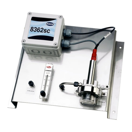
General Information 2.3 General Product Overview DANGER The 8362 sc High Purity Water pH or ORP sensor is not approved for hazardous locations. The 8362 sc High Purity Water pH/ORP panel is preplumbed and includes the 8362 sc High Purity Water Sensor (Figure 1), digital electronics junction box, flow meter, and mounting assembly. -
Page 9: General Information
General Information Figure 1 8362 Probe Components pH or ORP cable assembly (Cat. No. 359016,10110) Mounting bracket pH (Cat. No. 08362=A=0000) electrode or 10. M6 x 10 mm and M6 lock washer screw (2) ORP (Cat. No. 08362=A=1111) electrode Electrode support 11. - Page 10 Visit us at www.hach.com...
-
Page 11: Section 3 Installation
1. The panel is mounted to a wall or other hard and stable surface. Choose a convenient location to read the flow meter and to run cables from the controller to the panel and the junction box. Extension cables are available through Hach, refer to Replacement Parts and Accessories on page 2. -
Page 12: Preparing For System Measurement
Installation Figure 2 Panel Mounting Dimension 3.2 Preparing for System Measurement 1. Remove the measurement chamber (see Figure 1 on page 2. Remove the protective cap covering the electrode bulb and rinse with demineralized water or pH buffer for pH measurement or ORP standard solution for ORP measurement. -
Page 13: Sample Connections
Installation 3.3 Sample Connections 1. Connect the sample stream flow to the sample-in port. 2. Connect a drain tube to the sample-out port. Note: It is not recommended to run the sample stream back into the main flow stream. 3. Introduce the sample and visually check the measurement chamber for bubbles that could disturb the measurement. - Page 14 Installation Figure 3 Measurement System Electrical Connection to Digital Gateway...
- Page 15 Installation Figure 4 Junction Box Wiring Table 1 Junction Box Wiring Information pH/ORP Electrode Temperature Sensor Black–Rigid (center) wire = measuring pH or ORP Brown and white wire = Pt100 Green–Copper internal shield = reference Green–Copper external shield= connect to the ground plane of the transmitter...
- Page 16 Visit us at www.hach.com...
-
Page 17: Section 4 Sc100 Operation
Section 4 sc100 Operation 4.1 Using the sc100 Controller The front of the controller is shown in Figure 5. The keypad consists of the eight keys described in Table Figure 5 Front of the Controller sc100 Instrument display IrDA Port BACK HOME MENU... -
Page 18: Sc100 Display Features
sc100 Operation 4.1.1 sc100 Display Features When a sensor is connected and the controller is in measurement mode, the controller automatically identifies the connected sensors and displays associated measurements. The display will flash on startup, when a sensor error has occurred, and when a sensor is being calibrated. -
Page 19: Sensor Setup
sc100 Operation 4.2 Sensor Setup When a sensor is initially installed, the serial number of the sensor will be displayed as the sensor name. To change the sensor name refer to the following instructions: 4.2.1 Changing the Sensor Name Step Select Menu Level/Instructions Confirm... -
Page 20: Sensor Diagnostics Menu
sc100 Operation 4.4 Sensor Diagnostics Menu SELECT SENSOR ERROR LIST–See section 7.1 on page WARNING LIST–See section 7.2 on page 4.5 pH Sensor Setup Menu SELECT SENSOR (if more than one sensor is attached) CALIBRATE 1 POINT AUTO Calibration with a single buffer — normally pH 7. 2 POINT AUTO Calibration with two buffers —... -
Page 21: Orp Sensor Setup Menu
sc100 Operation 4.5 pH Sensor Setup Menu (continued) CONFIGURE (continued) SELECT BUFFER Select the buffer type (standard 4, 7, 10 or DIN 19267) from the displayed choices. PURE H20 COMP Allows the user to specify that ammonia, morpholine, or other user-defined electrolyte is being used in the application, allowing a temperature-dependent linear slope factor to be applied to the measured pH. - Page 22 sc100 Operation 4.6 ORP Sensor Setup Menu (continued) CONFIGURE EDIT NAME Enter up to a 10-digit name in any combination of symbols and alpha or numeric characters. SELECT SENSOR Choose from the displayed sensor type (pH or ORP). TEMP UNITS Choose from the displayed options (°C or °F).
-
Page 23: Ph Calibration
sc100 Operation 4.7 pH Calibration DANGER Handling chemical samples, standards, and reagents can be dangerous. Review the necessary Material Safety Data Sheets and become familiar with all safety procedures before handling any chemicals. The manufacturer offers one and two point automatic and manual calibrations for pH. An automatic calibration identifies the buffer table corresponding to the chosen buffer and automatically calibrates the probe after it stabilizes. -
Page 24: Buffer Solutions (Ph)
sc100 Operation Figure 7 Measurement System—Removing the Flow Chamber 4.7.2 Buffer Solutions (pH) The pH of buffer solutions are dependent on temperature. The nominal pH values are referenced to a temperature of 25 °C (77 °F). Refer to Table 3 for NIST standard buffer solutions and DIN buffer values for a variety of temperatures. -
Page 25: Two Point Automatic Calibration Method
sc100 Operation Table 3 NIST and DIN Buffers NIST Buffer DIN Buffer Temp (°C) Buffer 4.00 Buffer 6.88 Buffer 9.00 Buffer 4.00 Buffer 6.88 Buffer 9.00 4.01 6.984 9.464 4.05 7.13 9.24 6.951 9.395 4.04 7.07 9.16 6.923 9.332 4.02 7.05 9.11 9.276... -
Page 26: One Point Automatic Calibration Method (Optional)
sc100 Operation 4.7.3 Two Point Automatic Calibration Method (continued) Step Select Menu Level/Instructions Confirm 2 Point Auto. Press When Stable. ENTER 2 Point Auto Complete Slope: XX.X mV/pH Return Probe to Process Main Menu or Main Measurement Screen — 4.7.4 One Point Automatic Calibration Method (optional) Step Select Menu Level/Instructions... -
Page 27: Two Point Manual Calibration Method
sc100 Operation 4.7.5 Two Point Manual Calibration Method Step Select Menu Level/Instructions Confirm MAIN MENU — SENSOR SETUP Highlight the appropriate sensor if more than one sensor is attached. CALIBRATE 2 POINT MANUAL CAL OUTPUT MODE (ACTIVE, HOLD, or TRANSFER) 2 Point Manual. -
Page 28: One Point Manual Calibration Method (Optional)
sc100 Operation 4.7.6 One Point Manual Calibration Method (optional) Step Select Menu Level/Instructions Confirm MAIN MENU — SENSOR SETUP Highlight the appropriate sensor if more than one sensor is attached. — CALIBRATE — 1 POINT MANUAL OUTPUT MODE (ACTIVE, HOLD, or TRANSFER) 1 Point Manual. -
Page 29: Orp Calibration
sc100 Operation 4.8 ORP Calibration The manufacturer offers a one point manual calibration for ORP. The value of the sample used in the manual calibration may be determined by laboratory analysis or comparison reading. 4.8.1 ORP Calibration Procedure For a precise calibration of the ORP electrode, a standard solution is required. The manufacturer recommends using a one point standard solution calibration. -
Page 30: One-Point Manual Calibration
sc100 Operation 4.8.2 One-point Manual Calibration Step Select Menu Level/Instructions Confirm MAIN MENU — SENSOR SETUP Highlight the appropriate sensor if more than one sensor is attached. — CALIBRATE — 1 POINT MANUAL CAL OUTPUT MODE (ACTIVE, HOLD, or TRANSFER) 1 Point Manual. - Page 31 sc100 Operation Figure 8 Overflow Sampling...
-
Page 32: Concurrent Calibration Of Two Sensors For Ph And Orp
sc100 Operation 4.10 Concurrent Calibration of Two Sensors for pH and ORP 1. Begin a calibration on the first sensor and continue until “Wait to Stabilize” is displayed. Press the key. BACK 2. Highlight LEAVE and press . The display will return to the main measurement ENTER screen. -
Page 33: Section 5 Sc1000 Operation
Section 5 sc1000 Operation 5.1 Using the sc1000 Controller The sc1000 is a touch screen application. Use your finger to touch keys and menu commands. In normal operation the touch screen displays the measured values for the sensors selected. 5.1.1 Display Features 5.1.1.1 Using the Pop-up Toolbar The pop-up toolbar provides access to the controller and sensor settings. -
Page 34: Navigating The Menu Windows
sc1000 Operation Figure 10 Main Menu MENU SENSOR STATUS SENSOR SETUP SYSTEM SETUP TEST/MAINT Display Area BACK FORWARD –confirms the entry or selection. ENTER –changes to the display of measured values. The pop-up toolbar cannot open from the menu window. To view the HOME Main Menu from this display, touch the Home button and then the bottom of the screen. - Page 35 sc1000 Operation Figure 11 Changing a Menu Item Display Area –changes to the display of measured values. HOME –scrolls up BACK –scrolls down FORWARD DOWN –confirms the entry or selection. ENTER Figure 12 Keypad Enters numbers or the character as shown on the button. Moves the cursor one position to the left or to the right.
-
Page 36: Sensor Setup
sc1000 Operation Figure 13 List Box mg/l Scrolls up or down –cancels and entry. CANCEL –confirms a selection. ENTER Figure 14 Message window COMMUNICATION ERROR Ph [11f20030007] Scrolls up or down. Displays the messages or warnings. Displays details on the selected entry. This button changes back to the previous display. -
Page 37: Sensor Data Logging
sc1000 Operation 5.3 Sensor Data Logging The sc1000 provides a data log for each sensor. 1. Tap the bottom-left of the screen to display the pop-up toolbar and press MAIN MENU 2. From the Main Menu, select SENSOR SETUP and press ENTER 3. - Page 38 sc1000 Operation 5.5 pH Sensor Setup Menu (continued) CONFIGURE EDIT NAME Enter up to a 10-digit name in any combination of symbols and alpha or numeric characters. SELECT MEASURE Select the appropriate measurement units to display. DISPLAY FORMAT Select the measurement resolution (xx.xx pH or xx.x pH). TEMP UNITS Choose from the displayed options (°C or °F).
-
Page 39: Orp Sensor Setup Menu
sc1000 Operation 5.5 pH Sensor Setup Menu (continued) DIAG/TEST PROBE INFO Display the sensor type, entered name of the sensor (Default: Digital Gateway serial number and name), the sensor serial number, the software version number, and the sensor driver version number. CAL DATA Displays the pH slope and the date of the last calibration. - Page 40 sc1000 Operation 5.6 ORP Sensor Setup Menu (continued) CONFIGURE (continued) FILTER Select 0–60 second signal averaging time. TEMP ELEMENT Select type of temperature element from the displayed choices. CAL DAYS Number of days since the last calibration. Default notification at 60 days. SENSOR DAYS Number of days the sensor has been in operation.
-
Page 41: Ph Calibration
sc1000 Operation 5.7 pH Calibration DANGER Handling chemical samples, standards, and reagents can be dangerous. Review the necessary Material Safety Data Sheets and become familiar with all safety procedures before handling any chemicals. The manufacturer offers one and two point automatic and manual calibrations for pH. An automatic calibration identifies the buffer table corresponding to the chosen buffer and automatically calibrates the probe after it stabilizes. -
Page 42: Buffer Solutions (Ph)
sc1000 Operation Figure 15 Measurement System—Removing the Flow Chamber 5.7.1.1 Buffer Solutions (pH) The pH of buffer solutions are dependent on temperature. The nominal pH values are referenced to a temperature of 25 °C (77 °F). Refer to Table 4 for NIST standard buffer solutions and DIN buffer values for a variety of temperatures. -
Page 43: Two Point Automatic Calibration Method
sc1000 Operation Table 4 NIST and DIN Buffers (continued) NIST Buffer DIN Buffer Temp (°C) Buffer 4.00 Buffer 6.88 Buffer 9.00 Buffer 4.00 Buffer 6.88 Buffer 9.00 — 6.836 8.962 4.01 6.96 8.73 — 6.84 8.941 4.01 6.96 8.71 — 6.845 8.921 4.01... -
Page 44: Two Point Manual Calibration Method
sc1000 Operation 7. Press when stable. A screen will display 1 Point Auto Complete and the slope ENTER (XX.X mV/pH). 8. Return the probe to process. 5.7.4 Two Point Manual Calibration Method 1. Tap the bottom-left of the screen to display the pop-up toolbar and press MAIN MENU 2. -
Page 45: Orp Calibration
sc1000 Operation 5.8 ORP Calibration 5.8.1 ORP Calibration Procedure For a precise calibration of the ORP electrode, a standard solution is required. The manufacturer recommends using a one point standard solution calibration. Use the solution as follows: 1. Holding the flow chamber nut in position, unscrew the flow chamber. See Figure 15 on page 2. -
Page 46: Overflow Sample Method (Astm Method) Procedure
sc1000 Operation 5.9 Overflow Sample Method (ASTM Method) Procedure 1. Take a side-stream sample from a tap as close to the 8362 sc High Purity Sensor as possible. 2. Introduce the sample to the bottom of a large (500 mL) beaker through a clean tube extending to the bottom of the beaker. - Page 47 sc1000 Operation Figure 16 Overflow Sampling...
-
Page 48: Concurrent Calibration Of Two Sensors For Ph And Orp
sc1000 Operation 5.10 Concurrent Calibration of Two Sensors for pH and ORP 1. Begin a calibration on the first sensor and continue until “Wait to Stabilize” is displayed. 2. Select LEAVE and press . The display will return to the main measurement ENTER screen. -
Page 49: Section 6 Maintenance
Section 6 Maintenance DANGER Only qualified personnel should conduct the tasks described in this section of the manual. 6.1 Cleaning the Instrument With the junction box securely closed, wipe the exterior with a damp cloth. 6.2 Sensor/Electrode Maintenance Store the electrode in KCl solution to avoid damage during long term storage. Carefully clean the electrode monthly with a soft, non-abrasive cloth. - Page 50 Visit us at www.hach.com...
-
Page 51: Section 7 Troubleshooting
Section 7 Troubleshooting Table 5 General Troubleshooting Symptom Probable Cause Corrective Action Bad measuring or reference electrode. Replace defective electrode. Check the electrode cable to controller wiring. Make The electrode does not The wiring to the controller is incorrect. sure the wire connectors are contacting the metal calibrate. - Page 52 Visit us at www.hach.com...
-
Page 53: Section 8 Replacement Parts And Accessories
Section 8 Replacement Parts and Accessories Description Catalog Number 4 pH solution, NIST, 500 mL 2283449 7 pH solution, NIST, 500 mL 2283549 10 pH solution, NIST, 500 mL 2283649 Controller extension cable, 1 m (3.2 ft) 6122400 Controller extension cable, 7.6 m (25 ft) 57960–00 Controller extension cable, 15.2 m (50 ft) 5796100... - Page 54 Visit us at www.hach.com...
-
Page 55: Section 9 How To Order
Brief description or model number • Quantity International Customers Hach maintains a worldwide network of dealers and distributors. To locate the representative nearest you, send an e-mail to: intl@hach.com or contact: Hach Company World Headquarters; Loveland, Colorado, U.S.A. Telephone: (970) 669-3050; Fax: (970) 669-2932 Technical and Customer Service (U.S.A. -
Page 56: Section 10 Repair Service
Section 10 Repair Service Authorization must be obtained from Hach Company before sending any items for repair. Please contact the Hach Service Center serving your location. In the United States: Hach Company Ames Service 100 Dayton Avenue Ames, Iowa 50010 (800) 227-4224 (U.S.A. -
Page 57: Section 11 Limited Warranty
*one year* from date of shipment unless otherwise noted in the product manual. In the event that a defect is discovered during the warranty period, Hach Company agrees that, at its option, it will repair or replace the defective product or refund the purchase price, excluding original shipping and handling charges. - Page 58 Visit us at www.hach.com...
Need help?
Do you have a question about the 8362sc and is the answer not in the manual?
Questions and answers