
Subscribe to Our Youtube Channel
Related Manuals for Hach LDO


Summary of Contents for Hach LDO
- Page 1 Catalog Number 5790018 ™ Dissolved Oxygen Sensor USER MANUAL December 2006, Edition 6 © Hach Company, 2003–2006. All rights reserved. Printed in the U.S.A. eac/te/dp...
- Page 2 Visit http://www.hach.com...
-
Page 3: Table Of Contents
Table of Contents Section 1 Specifications............................5 Section 2 General Information ..........................7 2.1 Safety Information ............................... 7 2.1.1 Use of Hazard Information......................... 7 2.1.2 Precautionary Labels..........................7 2.2 General Sensor Information ..........................8 2.3 Theory of Operation ............................8 Section 3 Installation .............................. - Page 4 Table of Contents Section 8 Replacement Parts and Accessories....................31 Section 9 How to Order ............................33 Section 10 Repair Service............................. 34 Section 11 Limited Warranty ..........................35 Section 10 Compliance Information ........................37...
-
Page 5: Section 1 Specifications
Section 1 Specifications Specifications are subject to change without notice. Table 1 LDO Probe Specifications Corrosion-resistant materials, fully-immersible sensor with 10 m (30 foot) Components cable Measuring Range (Dissolved Oxygen) 0 to 20.00 ppm (0 to 20.00 mg/L) or 0 to 200% saturation Measuring Range (Temperature) 0 to 50 °C (32 to 122 °F) - Page 6 Visit us at www.hach.com...
-
Page 7: Section 2 General Information
Section 2 General Information 2.1 Safety Information Please read this entire manual before unpacking, setting up, or operating this equipment. Pay attention to all danger and caution statements. Failure to do so could result in serious injury to the operator or damage to the equipment. To ensure that the protection provided by this equipment is not impaired, do not use or install this equipment in any manner other than that specified in this manual. -
Page 8: General Sensor Information
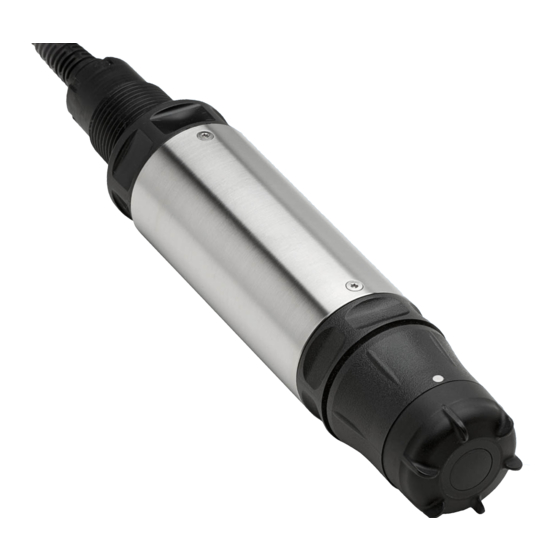
(probe with sensor cap) for in-situ measurement. The LDO sensor can be operated using the sc100 controller and the sc1000 controller. Refer to... -
Page 9: Section 3 Installation
DANGER Seul un technicien qualifié peut effectuer les tâches d'installation décrites dans cette section du manuel. The LDO system can be used with either an sc100 or sc1000 controller. Refer to section 3.1 for sc100 installation instructions and section 3.2 on page 13 for sc1000 installation instructions. -
Page 10: Hard-Wiring A Sc Sensor To The Controller
Installation Figure 2 Attaching the Sensor using the Quick-connect Fitting 3.1.1.2 Hard-wiring a sc Sensor to the Controller Important Note: Hard-wiring the sensor to the sc100 is not an approved method for Class I, Division 2 Hazardous Locations. 1. Disconnect power to the controller if powered. 2. - Page 11 Installation Table 2 Wiring the Sensor at Terminal Block J5 Terminal Number Terminal Designation Wire Color Data (+) Blue Data (–) White Service Request No Connection +12 VDC Brown Circuit Common Black Shield Shield (grey wire in existing quick-disconnect fitting) Figure 3 Hard-wiring the Sensor DATA...
-
Page 12: Connecting The Sc Sensor To A Controller In A Hazardous Location
Installation 3.1.2 Connecting the sc Sensor to a Controller in a Hazardous Location DANGER The sc100 and certain versions of the sensor are suitable for use in Class 1, Division 2, Groups A, B, C, D Hazardous Locations . See Control Drawing 5860078 in the sc100 Controller Manual, Cat. -
Page 13: Connecting The Sensor To The Sc1000
Note: Do not use the middle connection for the sensors as this is reserved for the display module. 3.3 Installing the Sensor in the Sample Stream To install the LDO in a sample stream, it is recommended to use either the optional pole mount (Cat. No. 5794400) or ball float mount (Cat. No. 5794300) as shown in... - Page 14 Installation Figure 5 Optional Pole Mount (Cat. No. 5794400) and Ball Float Mount (5794300) Installation aa aa aa aa aa aa aa aa aa aa aa aa Pipe locking knob Position pin removed for float assembly Pipe locking knob Adjustable angle (using position pin) Position pin...
-
Page 15: Section 4 User Interface And Navigation
Section 4 User Interface and Navigation 4.1 Using the sc100 Controller The front of the controller is shown in Figure 6. The keypad consists of the eight keys described in Table Figure 6 Front of the Controller sc100 Instrument display IrDA window BACK key HOME key... -
Page 16: Controller Display Features
User Interface and Navigation 4.1.1 Controller Display Features When a sensor is connected and the controller is in measurement mode, the controller automatically identifies the connected sensors and displays associated measurements. The display will flash on startup, when a sensor error has occurred, and when a sensor is being calibrated. -
Page 17: Using The Sc1000 Controller
User Interface and Navigation 4.2 Using the sc1000 Controller The sc1000 is a touch screen application. Use your finger to touch keys and menu commands. In normal operation the touch screen displays the measured values for the sensors selected. 4.2.1 Display Features 4.2.1.1 Using the Pop-up Toolbar The pop-up toolbar provides access to the controller and sensor settings. -
Page 18: Navigating The Menu Windows
User Interface and Navigation Figure 9 Main Menu MENU SENSOR STATUS SENSOR SETUP SYSTEM SETUP TEST/MAINT Display Area BACK FORWARD –confirms the entry or selection. ENTER –changes to the display of measured values. The pop-up toolbar cannot open from the menu window. To view the HOME Main Menu from this display, touch the Home button and then the bottom of the screen. - Page 19 User Interface and Navigation Figure 10 Changing a Menu Item Display Area –changes to the display of measured values. HOME –scrolls up BACK –scrolls down FORWARD DOWN –confirms the entry or selection. ENTER Figure 11 Keypad Enters numbers or the character as shown on the button. Moves the cursor one position to the left or to the right.
- Page 20 User Interface and Navigation Figure 12 List Box mg/l Scrolls up or down –cancels and entry. CANCEL –confirms a selection. ENTER Figure 13 Message window COMMUNICATION ERROR Ph [11f20030007] Scrolls up or down. Displays the messages or warnings. Displays details on the selected entry. This button changes back to the previous display.
-
Page 21: Section 5 Operation
Section 5 Operation 5.1 Sensor Setup When a sensor is initially installed, the serial number of the Digital Gateway will be displayed as the sensor name. To change the sensor name refer to the following instructions: 1. Select Main Menu. 2. -
Page 22: Sensor Setup Menu
Operation 5.4 Sensor Setup Menu SELECT SENSOR (if more than one sensor is attached) CALIBRATE AIR CAL Perform an air calibration of the sensor (slope calibration). See section 5.6.1 on page SAMPLE CAL Enter a value for the DO concentration as determined by another sensor or independent method. The instrument performs an offset calibration based on the entered value. -
Page 23: Pressure And Elevation
Operation 5.4 Sensor Setup Menu (continued) DIAG/TEST SOFTWARE VERS. Displays the software version number DRIVER VERS Displays the software driver version number. GAIN CORR User Editable—to change the calibration gain. Range: 0.000–3.0 OFFSET CORR User Editable—to change the calibration offset. Range: -3.0–3.0 PHASE DIAG Information only—updated once per second AMPL DIAG... -
Page 24: Calibration
Operation Table 4 Elevation Barometric Pressure Elevation in feet Barometric pressure in mm Hg Elevation in feet Barometric pressure in mm Hg 1000 7000 1500 7500 2000 8000 2500 8500 3000 9000 3500 9500 4000 10000 4500 10500 5000 11000 5500 —... -
Page 25: Sample Cal-Calibration By Comparison To A Winkler Titration
5.6.3 Sample Cal—Calibration by Comparison to a Hand-held DO Analyzer 1. Place the dissolved oxygen sensor as close to the LDO sensor as possible. 2. Wait for the hand-held DO analyzer to stabilize. 3. From the Main Menu, select SENSOR SETUP and confirm. -
Page 26: Concurrent Calibration Of Two Sensors
Operation 5. Select CALIBRATE and confirm. 6. Select SAMPLE CAL. Select the available Output Mode (Active, Hold, or Transfer) from the list box and confirm. 7. The display will show “Press when Stabilized” and the current DO and ENTER temperature readings. When the reading has been confirmed or when the reading has been accepted as stable, the display will change to an entry screen. -
Page 27: Section 6 Maintenance
Section 6 Maintenance DANGER Only qualified personnel should conduct the tasks described in this section of the manual. DANGER Seul un technicien qualifié peut effectuer les tâches d'installation décrites dans cette section du manuel. DANGER Explosion hazard. Do not connect or disconnect equipment unless power has been switched off or the area is known to be non-hazardous. - Page 28 Visit us at www.hach.com...
-
Page 29: Section 7 Troubleshooting
Section 7 Troubleshooting 7.1 Error Codes When a sensor is experiencing an error condition, the sensor reading on the measurement screen will flash and all relays and analog outputs associated with this sensor will be held. The following conditions will cause the sensor reading to flash: Sensor calibration, Relay timer washing cycle, Loss of communication. -
Page 30: Troubleshooting
Troubleshooting Table 7 Warning Codes Displayed Definition Resolution Warning The EEPROM was corrupted. Values have EE SETUP ERR Contact the Service Department. been set to factory defaults. The EEPROM was corrupted. Values have EE RSRVD ERR Contact the Service Department. been set to factory defaults. -
Page 31: Section 8 Replacement Parts And Accessories
Cat. No. Instruction manual, LDO System, English each 5790018 LDO Probe with one sensor cap and 5 calibration bags each 5790000 LDO Probe with one sensor cap and 5 calibration bags, Hazardous Locations each 5790001 Sensor cap, replacement each 5791100 Accessories Description Cat. - Page 32 Visit us at www.hach.com...
-
Page 33: Section 9 How To Order
Brief description or model number • Quantity International Customers Hach maintains a worldwide network of dealers and distributors. To locate the representative nearest you, send an e-mail to: intl@hach.com or contact: Hach Company World Headquarters; Loveland, Colorado, U.S.A. Telephone: (970) 669-3050; Fax: (970) 669-2932 Technical and Customer Service (U.S.A. -
Page 34: Section 10 Repair Service
Section 10 Repair Service Authorization must be obtained from Hach Company before sending any items for repair. Please contact the Hach Service Center serving your location. In the United States: Hach Company Ames Service 100 Dayton Avenue Ames, Iowa 50010 (800) 227-4224 (U.S.A. -
Page 35: Section 11 Limited Warranty
In the event that a defect is discovered during the warranty period, Hach Company agrees that, at its option, it will repair or replace the defective product or refund the purchase price excluding original shipping and handling charges. - Page 36 Visit us at www.hach.com...
-
Page 37: Section 10 Compliance Information
Section 10 Compliance Information Hach Co. certifies this instrument was tested thoroughly, inspected and found to meet its published specifications when it was shipped from the factory. The Model sc100 Controller/sc1000 Controller with the LDO Probe has been tested and is... - Page 38 Canadian Interference-causing Equipment Regulation, IECS-003, Class A Supporting test records by Hewlett Packard, Fort Collins, Colorado Hardware Test Center (A2LA # 0905-01) and certified compliance by Hach Company. This Class A digital apparatus meets all requirements of the Canadian Interference- Causing Equipment Regulations.
- Page 39 Appendix A Modbus Register Information Table 8 Sensor Modbus Registers Group Name Tag Name Register # Data Type Length Units (U) Range Oxygen Measurements 40001 Float 0..20 Concentration Percent Measurements 40003 Float Percent 0..300 Saturation Celsius/ Measurements Temperature 40005 Float -5.1..60 / 0..150 Fahrenheit Total Phase...
- Page 40 Visit us at www.hach.com...
- Page 41 Index Applications ..............8 Maintenance Schedule ..........27 Menu command Marking ............17 Buttons Menu windows ............17 List box .............. 19 Mounting Toolbar .............. 17 Probe ..............14 Calibration ..............24 Normal operation ............. 17 Air ..............26 Cleaning Sensor ...............
- Page 42 Visit us at www.hach.com...
Need help?
Do you have a question about the LDO and is the answer not in the manual?
Questions and answers