
Related Manuals for Hach ORBISPHERE A1100


Summary of Contents for Hach ORBISPHERE A1100
- Page 1 DOC024.52.93018 ORBISPHERE Model A1100 Oxygen Sensor USER MANUAL 10/2018, Edition 8...
-
Page 3: Table Of Contents
Table of Contents Section 1 General Information ......................3 1.1 Disclaimer ............................ 3 1.2 Safety information ........................3 1.2.1 Use of hazard information ....................3 1.2.2 Service and repairs ......................3 1.2.3 Precautionary labels......................4 1.3 Product recycling information....................... 5 1.4 Product disposal .......................... - Page 4 Table of Contents...
-
Page 5: Section 1 General Information
However, Hach Lange assumes no responsibility for any inaccuracies that may be contained in this manual. In no event will Hach Lange be liable for direct, indirect, special, incidental, or consequential damages resulting from any defect or omission in this manual, even if advised of the possibility of such damages. -
Page 6: Precautionary Labels
General Information 1.2.3 Precautionary labels Read all labels and tags attached to the sensor. Personal injury or damage to the sensor could occur if not observed. This symbol, if noted on the product, indicates the need for protective eye wear. This symbol indicates the need for protective hand wear. -
Page 7: Product Recycling Information
General Information 1.3 Product recycling information ENGLISH Electrical equipment marked with this symbol may not be disposed of in European public disposal systems after 12 August 2005. In conformity with European local and national regulations (EU Directive 2002/96/EC), European electrical equipment users must now return old or end-of-life equipment to the manufacturer for disposal at no charge to the user. - Page 8 General Information SVENSKA Elektronikutrustning som är märkt med denna symbol kanske inte kan lämnas in på europeiska offentliga sopstationer efter 2005-08-12. Enligt europeiska lokala och nationella föreskrifter (EU-direktiv 2002/96/EC) måste användare av elektronikutrustning i Europa nu återlämna gammal eller utrangerad utrustning till tillverkaren för kassering utan kostnad för användaren. Obs! Om du ska återlämna utrustning för återvinning ska du kontakta tillverkaren av utrustningen eller återförsäljaren för att få...
-
Page 9: Product Disposal
European public disposal systems after 12 August 2005. Hach Lange will offer to take back (free of charge to the customer) any old, unserviceable or redundant analyzers and systems which carry the above symbol, and which were originally supplied by Hach Lange. -
Page 10: Restriction Of Hazardous Substances (Rohs)
Currently, monitoring and control instruments do not fall within the scope of the RoHS Directive, however Hach Lange has taken the decision to adopt the recommendations in the Directive as the target for all future product design and component purchasing. -
Page 11: Section 2 Technical Specifications
Section 2 Technical Specifications Specifications are subject to change without notice. 2.1 Sensor weight and dimensions The sensor weight is approximately 300 grams. Figure 1 Sensor dimensions 2.2 ORBISPHERE family of A1100 oxygen sensors Model A1100 non-ATEX sensors • Electrochemical oxygen sensor •... -
Page 12: Sensor Configurations For Standard Applications
Technical Specifications 2.3 Sensor configurations for standard applications Table 1 Sensor configurations for standard applications Application Sensor Membrane Cartridge Protection Cap 2958A-A (optimized response time) Beer with 3650 Portable A1100-S00 33051-SP 2952A-A (optimized maintenance interval) Beer in-line A1100-S00 2952A-A 33051-SG Wort in-line A1100-S00 29552A-A... -
Page 13: Sensor Membrane Specifications
Technical Specifications 2.4 Sensor membrane specifications 2.4.1 Oxygen sensors (Table 1) Table 2 Membrane specifications - Oxygen sensors (1) 2956A-A 2958A-A 29552A-A 2952A-A In line wort, Corrosion control, Corrosion control, Beverage, Recommended applications Air/O injection, In line beverage, De-aerated water Lab. -
Page 14: Oxygen Sensors (Table 2)
Technical Specifications 2.4.2 Oxygen sensors (Table 2) Table 3 Membrane specifications - Oxygen sensors (2) 2935A-A 29521A-A 2995A-A Saturated to super Saturated to super In line hot wort Recommended applications saturated levels saturated levels (up to 70°C) ® ® ® Material Halar Tefzel... -
Page 15: Section 3 Introduction
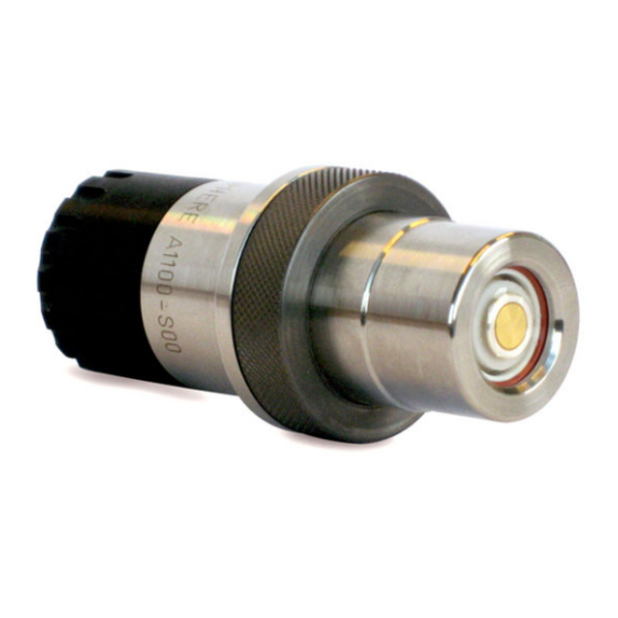
Section 3 Introduction 3.1 What you have received 3.1.1 A1100 electrochemical sensor The sensor may be delivered separately or as part of an ORBISPHERE system, depending on the individual order. Figure 2 A1100 sensor with storage cap and base The sensor (as illustrated in Figure 2 above) will be delivered fitted with a plastic screw-on storage cap to protect the sensor head. -
Page 16: Sensor Recharge Kit
Introduction 3.1.3 Sensor recharge kit A recharge kit (as illustrated in Figure 4 below) should have been ordered with the sensor as this will be required to initially make the sensor operational. It is also required for sensor cleaning and membrane replacement procedures. Note: The recharge kit for oxygen has a blue sticker on the front of the box. -
Page 17: Sensor Components
Introduction The cotton washers provide additional protection against the formation of deposits and residue on the center electrode and anode, which prolongs the time period required between sensor services. The silicone discs are required for measurements in ultra-pure water or water containing ammonia. -
Page 18: Basic Principle Of Operation
Introduction 3.3 Basic principle of operation In its simplest form, the electrochemical sensor consists of one center electrode (cathode) and one counter electrode (anode) immersed in an electrolyte solution which is separated from the gaseous or liquid sample by a gas permeable membrane. An electronic circuit is linked to the anode and cathode. -
Page 19: Section 4 Installation
The sensor has been delivered with a single protection cap. The following instructions detail the steps required to make the sensor operational. Should you have any questions, your Hach Lange representative will be pleased to help. CAUTION Avoid all eye and skin contact with the electrolyte in the sensor and replacement cartridge as it is corrosive and can cause burning. - Page 20 Installation 3. Hold the sensor with the membrane facing down to avoid spilling any electrolyte, then carefully unscrew the shipment cartridge. Drain the old electrolyte into a sink and flush away. Discard the shipment cartridge and membrane. 4. Remove the cotton washer from the top of the anode and discard.
- Page 21 Installation Note: During this step, it is very important to ensure your finger does not come into contact with the cathode (golden surface) as it could leave greasy deposits on the surface. 7. Take a silicone disc from the recharge kit, hold it between thumb and forefinger and position it on top of the anode.
- Page 22 Installation 12. Hold the container steady between thumb and forefinger of one hand. 13. Lower the sensor into the container until the top of the anode is covered with electrolyte. 14. Leave for a few seconds to ensure the cotton washer has fully absorbed some of the electrolyte and that it is no longer dry.
- Page 23 Installation 18. Rinse the sensor under a tap for about 5 seconds to remove any excess electrolyte, then gently wipe with a soft tissue to ensure all parts are completely dry. 19. Drain the overflow electrolyte from the container into a sink and flush away. 20.
-
Page 24: Sensor Installation
Note: There may be situations where not all the above conditions can be met. If this is the case, or you have any concerns, please consult your Hach Lange representative to appraise the situation and define the best applicable solution. -
Page 25: Sensor Insertion
Installation 4.2.2 Sensor insertion Note: Check that the small O-ring at the bottom of the flow chamber is present during removal and installation of the sensor, as it may stick to the sensor head and fall. • Insert the sensor straight into the flow chamber or socket. •... -
Page 26: Mounting Accessories
Installation 4.3 Mounting accessories 4.3.1 External pressure sensor The system can be fitted with an external pressure sensor. This enables a measurement of fraction of gas under variable pressure conditions during gas phase measurement. Two models are available, depending on application: •... -
Page 27: The 32003 Insertion/Extraction Valve
Installation Recommendation: To facilitate sensor removal and installation, we suggest installing the socket in a location where the liquid can be drained quickly and easily. By creating a one meter long piece of pipe (shown below) with shut off valves at both ends, just a small volume of liquid needs to be drained to enable sensor removal. -
Page 28: The 33095 Sensor Housing
Installation 4.3.4 The 33095 sensor housing The ORBISPHERE 33095 sensor housing is also available for use with the A1100 sensor but requires that the sample flow be turned off prior to insertion or removal of the sensor. Sensor insertion is made by inserting the sensor into the housing and tightening the retaining collar until it stops. - Page 29 Installation Table 4 Flow Chamber Orientation Sample Orientation of flow chamber Vertically, with connections down and sensor up Gaseous or liquid media - Center connection is the inlet - Outer connection is the outlet Horizontally, to allow for drainage Gaseous media, with occasional - Center connection (inlet) must be up liquid or vapor...
-
Page 30: Multi-Parameter Flow Chamber
Installation 4.3.7 Multi-parameter flow chamber Note: Suitable only for gaseous media. The ORBISPHERE 32002.xxx multi parameter flow chamber can accommodate one or two sensors and one sample pressure sensor. If only one gas sensor is used, the unused socket is plugged with the stainless steel plugs provided (model 28123). -
Page 31: Section 5 Maintenance And Troubleshooting
Section 5 Maintenance and Troubleshooting 5.1 Maintenance 5.1.1 Maintenance schedule The following table shows the recommended schedule for membrane replacement. The table should only be used as a guideline, as maintenance intervals will vary depending on a number of different parameters (e.g. water chemistry, CIP frequency, oxygen levels, sample temperature, etc.). -
Page 32: Membrane Replacement And Sensor Head Cleaning
Maintenance and Troubleshooting 5.1.3 Membrane replacement and sensor head cleaning A sensor recharge kit is required as it contains all the required components necessary for this membrane replacement and sensor head cleaning process (see details in Sensor recharge kit on page 14). - Page 33 Maintenance and Troubleshooting 3. Hold the sensor with the membrane facing down to avoid spilling any electrolyte, then carefully unscrew the old cartridge. Drain the old electrolyte into a sink and flush away. Discard the old cartridge and membrane. 4. Remove the cotton washer and silicone disc from the top of the anode and discard.
- Page 34 Maintenance and Troubleshooting 10. Clean by rotating the cleaning tool over the sensor head for a few seconds, in a clockwise direction only. 11. Remove the tool and tap it face down on a flat work surface to remove any powdery deposit.
- Page 35 Maintenance and Troubleshooting 16. Screw the polishing tool (DG33303) onto the top of the sensor. 17. Polish the electrodes by moving the sensor face in a circular direction against the liquid in the polishing cloth for about 30 seconds. 18. Remove the polishing tool from the sensor. 19.
- Page 36 Maintenance and Troubleshooting 20. Remove the plastic base from the bottom of the sensor and connect the sensor to the sensor cleaning and regeneration center (32301). 21. Push the cleaning tool over the sensor head. 22. For DG33619 regeneration cell, screw the regeneration cell on the sensor head.
- Page 37 Maintenance and Troubleshooting 27. On the sensor cleaning and regeneration center, turn the knob to the Cathode position and press the TIMER switch. Again, watch for the formation of bubbles and repeat the cleaning process if necessary. 28. When cleaning is complete, unplug the sensor from the cleaning center and re-install the plastic sensor base for the rest of the procedure.
- Page 38 Maintenance and Troubleshooting Note: During this step, it is very important to ensure your finger does not come into contact with the cathode (golden surface) as it could leave greasy deposits on the surface. 33. Take a silicone disc from the recharge kit, hold it between thumb and forefinger and position it on top of the anode.
- Page 39 Maintenance and Troubleshooting 38. Hold the container steady between thumb and forefinger of one hand. 39. Lower the sensor into the container until the top of the anode is covered with electrolyte. 40. Leave for a few seconds to ensure the cotton washer has fully absorbed some of the electrolyte and that it is no longer dry.
- Page 40 Maintenance and Troubleshooting 44. Rinse the sensor under a tap for about 5 seconds to remove any excess electrolyte, then gently wipe with a soft tissue to ensure all parts are completely dry. 45. Drain the overflow electrolyte from the container into a sink and flush away.
- Page 41 Maintenance and Troubleshooting 50. Push the protection cap firmly into place, making sure one of the four slots in the protection cap fits over the small locking pin (highlighted right). If it is necessary to turn the protection cap to fit over the locking pin, ensure you only turn it clockwise to avoid unscrewing the cartridge.
-
Page 42: Troubleshooting
Maintenance and Troubleshooting 5.2 Troubleshooting Table 7 Troubleshooting Problem Probable cause Possible solution Instrument internal barometric pressure Calibrate using a certified barometer. Do sensor needs calibration. not correct for sea level ! Sensor won't calibrate, even after cleaning and/or membrane change. Wet membrane interface. -
Page 43: Section 6 Accessories And Spare Parts
Section 6 Accessories and Spare Parts 6.1 Accessories Table 8 Sensor accessories Part N° Description 28117 Pressure sensor, 0-5 bar absolute 28117.C Pressure sensor, 0-1 bar absolute 6.2 Flow chambers and installation devices Table 9 Flow chambers and installation devices Part N°... -
Page 44: Sensor Spare Parts
Stainless steel 28mm cap with grille for ORBISPHERE A1100 family EC sensors. For use with 3625 package 33051-SP analyzer and 3650 instrument when measuring beer or soft-drinks. Stainless steel cap with a 6 branch grille for ORBISPHERE A1100 family EC sensors. For use with 6110 Total 33051-ST Package Analyzer. -
Page 45: Other Spare Parts
Accessories and Spare Parts 6.5 Other spare parts Table 12 Other spare parts Part N° Description 28093.0 EPDM O-rings for pressure sensor 28117.X. 18.78 x 1.78mm. (5 pieces) 28093.2 Kalrez O-ring for pressure sensor 28117.X. 18.78 x 1.78mm. (1 piece) 28093.4 Nitril O-rings for pressure sensor 28117.X. - Page 46 Accessories and Spare Parts...
- Page 47 Tel. +49 (0) 2 11 52 88-320 SWITZERLAND Fax (970) 669-2932 Fax +49 (0) 2 11 52 88-210 Tel. +41 22 594 6400 orders@hach.com info-de@hach.com Fax +41 22 594 6499 www.hach.com www.de.hach.com © Hach Company/Hach Lange GmbH, 2014–2015, 2018. All rights reserved.
Need help?
Do you have a question about the ORBISPHERE A1100 and is the answer not in the manual?
Questions and answers