Hach Flo-Dar User Manual
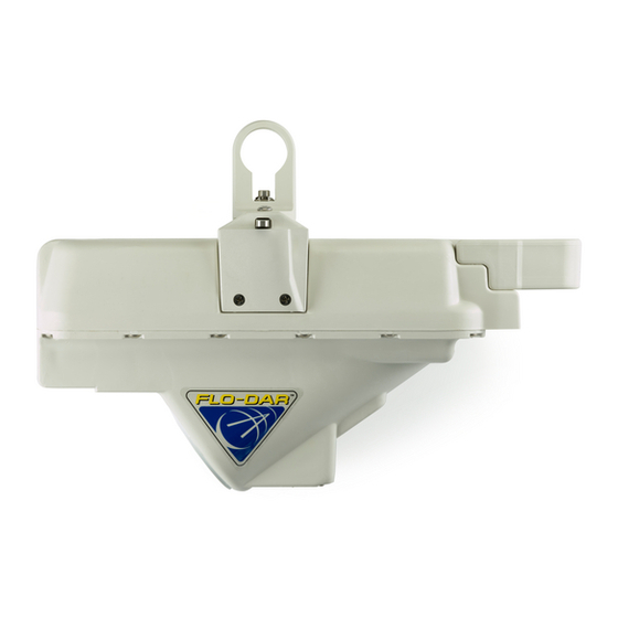
Flo-dar sensor
Hide thumbs
Also See for Flo-Dar:
- Basic user manual (286 pages) ,
- User manual (45 pages) ,
- User manual (24 pages)
Table of Contents
Advertisement
Quick Links
Advertisement
Table of Contents

Subscribe to Our Youtube Channel
Related Manuals for Hach Flo-Dar


Summary of Contents for Hach Flo-Dar
- Page 1 DOC343.53.80380 Flo-Dar Sensor 09/2019, Edition 6 User Manual...
-
Page 3: Table Of Contents
3.1.2.2 Install the frame on the wall ............15 3.1.2.3 Install the sensor on the frame ............17 3.1.2.4 Align the sensor vertically – Flo-Dar without SVS ......18 3.1.2.5 Align the sensor vertically – Flo-Dar with SVS ....... 19 3.1.2.6 Align the sensor horizontally ............ - Page 4 Table of Contents...
-
Page 5: Section 1 Specifications
Standard length: 9 m (30 ft); maximum length: 305 m (1000 ft) Depth measurement Method: Ultrasonic Standard operating range from Flo-Dar sensor housing to liquid: 0–152.4 cm (0–60 in.) Optional extended operating range from transducer face to liquid: 0–6.1 m (0–20 ft) (with 43.18 cm (17 in.) deadband), temperature compensated Accuracy: ±1%;... -
Page 6: Section 2 General Information
±5% of reading is typical where flow is in a channel with uniform flow conditions and is not surcharged, ±1% full scale maximum Surcharge conditions depth/velocity Depth (standard with Flo-Dar sensor) Surcharge depth supplied by Flo-Dar sensor Velocity (with optional surcharge velocity Method: Electromagnetic sensor) Range: ±4.8 m/s (±16 ft/s) -
Page 7: Precautionary Labels
2.1.2 Precautionary labels Read all labels and tags attached to the instrument. Personal injury or damage to the instrument could occur if not observed. A symbol on the instrument is referenced in the manual with a precautionary statement. This is the safety alert symbol. Obey all safety messages that follow this symbol to avoid potential injury. -
Page 8: Eu/Fcc/Ic/Anatel Regulations
Any changes or modifications to the device may void the user’s authority to operate this equipment. • Any service that includes the transmitter must only be done by Hach Company. • This device is considered a “mobile” wireless device per the FCC. For RF exposure safety, the user must maintain a minimum of 20 cm (8 in.) separation distance from the face of the radar... -
Page 9: Product Overview
2.3 Product overview The Flo-Dar sensor measures the flow velocity and liquid depth in open channels using radar and ultrasonic technology. The unit is made to withstand submersion during surcharge conditions. The optional surcharge velocity sensor supplies velocity measurements during surcharge conditions. -
Page 10: Velocity Measurements During Surcharge
The depth sensor on the Flo-Dar unit can measure distances up to 1.5 m (5 ft). For larger channels, an extended range sensor is available to measure up to 6.1 m (20 ft). - Page 11 4 Surcharge velocity sensor (SVS) (optional) 2 Extended range sensor (optional) 5 Flo-Dar connector and SVS connector 3 Bubble level 6 Flo-Dar with bare-wire and SVS with bare-wire Figure 3 Wall mount hardware 1 Wall mount bracket 7 Standard frame 2 Spacer, 12-inch 8 Spacer, 2¼-inch...
-
Page 12: Section 3 Installation
Section 3 Installation D A N G E R Explosion hazard. Trained personnel only must install or commission the equipment. 3.1 Mechanical installation 3.1.1 Site location guidelines N O T I C E To prevent damage to the enclosure, install the instrument away from direct sunlight, ultraviolet radiation (UV), heat sources and severe weather. - Page 13 Figure 5 Sensor location near a curve or elbow 1 Acceptable upstream sensor location 3 Distance downstream: 10 × pipe diameter 2 Acceptable downstream sensor location 4 Distance upstream: 5 × pipe diameter English 11...
-
Page 14: Install The Sensor
• Ultrasonic pressure: > 110 dB at 1 m (3.3 ft) on axis • Sound pressure inside beam: 111.9 dB maximum Mount the Flo-Dar sensor above the open channel on the wall of the manhole. For hazardous locations, a barrier must be installed outside of the hazardous area. - Page 15 Figure 7 Sensor dimensions 1 Optional extended range sensor 3 Minimum clearance for cable 2 Minimum clearance for cable with extended range sensor English 13...
-
Page 16: Assemble The Clamps On The Frame And Wall Bracket
Figure 8 Sensor with SVS dimensions 1 Minimum clearance for cable Figure 9 Standard frame dimensions 1 579.12 mm (22.8 in.) with 2¼ in. spacer; 828.04 mm (32.6 in.) with 12 in. spacer 3.1.2.1 Assemble the clamps on the frame and wall bracket Install the clamps on the frame and wall mount bracket before installation on the wall. -
Page 17: Install The Frame On The Wall
Items to collect: Wall mount hardware (Figure 3 on page 9) • Frame • Wall mount bracket • Clamps • Hardware: wall bracket, spacer, nuts and bolts 1. Put two clamp halves (one with threads and one without threads) around the wall mount bracket. Refer to Figure 2. - Page 18 Review the guidelines that follow to find the best location for the sensor. • Examine the upstream and downstream flow characteristics. Use a mirror if necessary. Install the sensor above the water where the flow is stable. Do not install the sensor where there are standing waves, pools or objects or materials that can disrupt the flow profile.
-
Page 19: Install The Sensor On The Frame
Figure 11 Wall installation 1 Distance from interior crown of pipe to top of frame 3 Washer 2 Anchor 4 Nut 3.1.2.3 Install the sensor on the frame The sensor fits in the frame in only one direction and is held in position when the bail on the sensor is turned. -
Page 20: Align The Sensor Vertically - Flo-Dar Without Svs
1 Bubble level 2 Bail 3.1.2.4 Align the sensor vertically – Flo-Dar without SVS The sensor must be aligned vertically to make sure that the sensor is above the flow and that the radar beam will not be stopped by the wall or pipe. Refer to Figure 1. -
Page 21: Align The Sensor Vertically - Flo-Dar With Svs
1 Spacer 2 Distance from interior crown of pipe to top of frame 3.1.2.5 Align the sensor vertically – Flo-Dar with SVS The sensor must be aligned vertically to make sure that the sensor is above the flow under normal full flow conditions and that the SVS is activated under surcharge conditions. -
Page 22: Align The Sensor Horizontally
1. Measure the vertical alignment and make adjustments if necessary. Refer to Align the sensor vertically – Flo-Dar without SVS on page 18 or Align the sensor vertically – Flo-Dar with SVS on page 19. 2. Measure the horizontal alignment and make adjustments if necessary. Refer to Align the sensor horizontally on page 20. - Page 23 Figure 15 Extended range sensor dimensions Figure 16 Extended frame dimensions 1 739.14 mm (29.1 in.) with 2¼ in. spacer; 985.52 mm (38.8 in.) with 12 in. spacer English 21...
-
Page 24: Measure The Sensor Offset
Figure 17 Vertical alignment with extended range sensor 1 Spacer 3.1.3 Measure the sensor offset The sensor offset is the distance from the top of the frame to the bottom of the pipe or channel. This distance will be entered into the software and is necessary for accurate flow calculations. If the optional extended range sensor is installed on the wall without the extended frame, the sensor offset is the distance from the surface of the extended range sensor to the bottom of the pipe or channel. -
Page 25: Measure The Pipe Diameter
Figure 18 Sensor offset 1 Distance from interior crown of pipe to top of frame 3 Sensor offset 2 Pipe diameter 3.1.4 Measure the pipe diameter The correct diameter of the pipe or channel is necessary for accurate flow calculations. 1. -
Page 26: Electrical Installation
Connect the Flo-Dar sensor to the flow logger. • FL900 flow logger—Connect the cable from the Flo-Dar sensor to a sensor connector on the flow logger. If the optional surcharge velocity sensor (SVS) is installed, connect the cable from the SVS to a sensor connector on the logger. -
Page 27: Attach The Desiccant Hub (Fl900)
Make sure that the latest version of the DATA Desktop software is installed on the computer. Download the software from http://www.hachflow.com. Click Support, then select Software Downloads>Hach FL Series Flow Logger. Section 5 Maintenance D A N G E R Multiple hazards. -
Page 28: Look For Corrosion And Damage
Look for corrosion and damage once a year. Note: The only parts of the Flo-Dar system that can be replaced by the user are the bail assembly and the cable. If the sensor becomes defective, it must be replaced as a complete unit. -
Page 29: Replace A Cable
3. Hook the bail on the sensor and turn the pole counter-clockwise to unlock the sensor from the frame. Remove the sensor. 4. Remove any debris from the bottom of the sensor. Clean the external surface of the sensor with mild soap and rinse with water. -
Page 30: Replace The Hydrophobic Membrane
Figure 21 Replace the desiccant 5.5 Replace the hydrophobic membrane Replace the hydrophobic membrane when: • Unexpected increases or decreases in level trends occur. • Level data is missing or incorrect, but the velocity data is valid. • The membrane is torn or has become saturated with water or grease. Refer to the illustrated steps that follow to replace the membrane. - Page 31 English 29...
-
Page 32: Section 6 Replacement Parts And Accessories
Section 6 Replacement parts and accessories W A R N I N G Personal injury hazard. Use of non-approved parts may cause personal injury, damage to the instrument or equipment malfunction. The replacement parts in this section are approved by the manufacturer. - Page 33 Accessories (continued) Description Item no. Jack-bar (temporary mount assembly), extended frame, 132.10–177.8 cm (52–70 in.) 800016302 manhole Jack-bar (temporary mount assembly), extended frame, 177.80–223.52 cm 800016303 (70–88 in.) manhole Jack-bar (temporary mount assembly), extended frame, 226.06–271.78 cm 800016304 (89–107 in.) manhole English 31...
- Page 34 32 English...
- Page 36 HACH COMPANY World Headquarters P.O. Box 389, Loveland, CO 80539-0389 U.S.A. Tel. (970) 669-3050 (800) 368-2723 (U.S.A. only) U.S.A. – orders@hach.com International – intlsupport@hach.com flowtechsupport@hach.com www.hachflow.com © Hach Company/Hach Lange GmbH, 2013–2019. All rights reserved.
Need help?
Do you have a question about the Flo-Dar and is the answer not in the manual?
Questions and answers