Table of Contents
Advertisement
Quick Links
Service Manual
EN
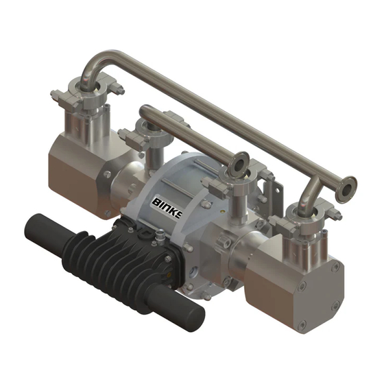
Maple 7/15 PSP Pump
• Model 104147
IMPORTANT! DO NOT DESTROY
It is the Customer's responsibility to have all operators and service personnel read and understand this
manual.
Contact your local Carlisle Fluid Technologies representative for additional copies of this manual.
READ ALL INSTRUCTIONS BEFORE OPERATING THIS PRODUCT
77-3300 R2.1
1/24
www.carlisleft.com
Advertisement
Table of Contents

Related Manuals for Binks Maple 7/15


Summary of Contents for Binks Maple 7/15
- Page 1 Service Manual Maple 7/15 PSP Pump • Model 104147 IMPORTANT! DO NOT DESTROY It is the Customer's responsibility to have all operators and service personnel read and understand this manual. Contact your local Carlisle Fluid Technologies representative for additional copies of this manual.
-
Page 2: Eu Declaration Of Conformity
Product Description / Object of Declaration: Pumps - Maple, DVP, 104009, 104010/LS, 104016, 104027, 104032, 104040/1/2, 104077, 104020, 104023, 104025, 104028/9, 106933, 104205,104149- 52, 104207-15, 104147. This Product is designed for use with: Solvent and Water based materials Suitable for use in hazardous area: Zone 1 Protection Level: II 2 G X IIB T4... - Page 3 In this part sheet, the words WARNING, CAUTION and NOTE are used to emphasize important safety information as follows: WARNING CAUTION NOTE Hazards or unsafe practices which could result in Hazards or unsafe practices which could result in Important installation, operation or maintenance minor personal injury, product or property severe personal injury, death or substantial property information.
-
Page 4: Specification
Specification Ratio: 15:1 Maximum air inlet pressure: 7 bar [101.5 psi] Maximum fluid pressure: 105 bar [1523 psi] Nominal flow volume / cycle: 0.166 l/m [0.044 US gal/m] Output @ 60 cycles / min: 10 l/m [2.6 US gal/m] Maximum recommended continous cycle rate:Cycles/min Maximum recommended intermittent cycle rate:Cycles/min 40 Fluid inlet connection: 1"... -
Page 5: Dimensions And Mounting Details
Dimensions and Mounting Details Outlet size: 1/2" NPT 1" Sanitary inlet Air inlet connection: 3/8" BSP/NPS MOUNTING LOCATIONS SECTION A-A 77-3300 R2.1 5/24 www.carlisleft.com... -
Page 6: Installation
Installation This product should be flushed with a suitable compatible solvent prior to use. Mount the pump securely and position the pump at a convenient height (below the lid height of the paint container), to allow for maintenance, visual observation, and periodic inspection. The wall mount bracket is included with all pumps. - Page 7 Installation Set the pump speed to a slow cycle rate and prime the pump to remove any air before increasing pressure. Inspect for any air or fluid leaks. Set the pump cycle rate to achieve the required paint volume and then adjust the system back pressure regulator and pump air pressure to achieve the desired system fluid pressure.
-
Page 8: Socket Head Cap Screw
Parts list - Pump Assembly ITEM PART NO. DESCRIPTION REMARKS 162746 Ø25.5 x 2 O-RING 165044 SPRING WASHER 165123 SPRING WASHER 165948 M10 x 40 SOCKET HEAD CAP SCREW 171792 3/4" BALL 177009 M12 x 35 SOCKET HEAD CAP SCREW 192009 1 &... -
Page 9: Pump Assembly
Pump Assembly = GREASE (AGMD-010) = LOCTITE = TORQUE = MAINTENANCE ORDER (Reverse for assembly) = GREASE INTERNAL (AGMD-010) 77-3300 R2.1 9/24 www.carlisleft.com... - Page 10 Parts list - Air Motor Assembly ITEM PART NO. DESCRIPTION REMARKS 0115-010037 POPPET ASSEMBLY 0115-010102 AIR VALVE ASSEMBLY 161992 Ø117.5 x 2.62 O-RING 161993 Ø20.35 x 1.78 O-RING 161994 Ø4.47 x1.78 O-RING 161995 Ø19.5 x 3.00 O-RING ...
- Page 11 77-3300 R2.1 11/24 www.carlisleft.com...
- Page 12 Air Motor Piston Assembly ITEM PART NO. DESCRIPTION REMARKS 162702 AIR MOTOR PISTON SEAL 165964 M12 x 40 GRUB SCREW 192759 PISTON SHAFT 192760 PISTON = GREASE (AGMD-010) = LOCTITE = TORQUE = MAINTENANCE ORDER (Reverse for assembly) = GREASE INTERNAL (AGMD-010) 77-3300 R2.1 12/24...
-
Page 13: Air Valve Assembly
Air Valve Assembly ITEM PART NO. DESCRIPTION REMARKS 0115-010015 SPOOL AND SLEEVE ASSEMBLY # Not Shown 162789 SPOOL AND SLEEVE O-RING 0115-010016 BUMPER 0115-010017 MAGNET 0115-010018 VALVE BLOCK END CAP 0115-010020 DIAPHRAGM 0115-010021 1.5 x 36 O-RING ... - Page 14 Fluid Piston Assembly ITEM PART NO. DESCRIPTION REMARKS 160523 PISTON BALL CHECK SPRING 162743 O-RING Ø33 x 2.0 162744 O-RING Ø23.52 x 2.0 162745 O-RING Ø29.9 x 1.78 171793 BALL Ø7/8" 193188 INLET SPRING KEEP 194287 SEAT 193358...
-
Page 15: Fault Finding
Fault Finding Symptom Possible Cause Remedy Air getting into the suction hose/manifold Check seals and hose connections. Pump will not Worn piston seal. Replace piston seals. ‘Prime’ Inspect, clean and/or replace Ball checks not seating correctly. balls and seats. Check air and fluid supply ball No Air or Fluid supply valves and supply hoses. - Page 16 Fault Finding Symptom Possible Cause Remedy Worn air motor piston seals. Replace air motor piston seal. Disassemble pump as required to Worn/failed air motor shaft seals. replace air motor shaft seals. Pump runs but has excessive pulsation. Worn fluid piston seal. Replace fluid piston seal.
- Page 17 Spares Kits for Maple 7/15 Pump KIT No. PART NO. DESCRIPTION REMARKS 250653 Fluid section seal kit Check main parts list for 250726 Fluid overhaul kit details of individual kit 250657 Air Motor Seal Kit contents 250628 Control Valve Kit ...
-
Page 18: Maintenance Schedule
Maintenance schedule Inspection Operation Daily Check for any general fluid or air leakage. Inspect Pump for Correct operation Weekly Check for any excessive mechanical noise Check for excessive fluid pressure pulsation Perform a pump stall test to ensure correct operation. If pump does not stall check fluid piston seals and ball checks, replace as required. -
Page 19: Bellows Replacement
Bellows Replacement ITEM PART NO. DESCRIPTION REMARKS 502769 Bellows positioning tool 502382 Bellows assembly spigot Screw Item No. 2 (assembly spigot) onto the piston shaft Using Item No. 1, push bellows over spigot until located in groove. Smear loctite 572 over nose of bellows, thread nut onto bellows ensuring the thread starts squarely. - Page 20 Accessories PART NO. DESCRIPTION REMARKS 192206 1" Sanitary Gasket Heavy duty 192009 1 & 1 1/2" Sanitary Clamp 1" Sanitary - 192532 1" BSPT (f) Adapter 502608 Seal Insertion Tool For Shaft seal (162703) 502769 Bellows Positioning Tool 502382 Bellows assembly spigot AGMD-010 Kluber Isoflex Topas NB 52 Grease 50ml...
- Page 21 NOTES 77-3300 R2.1 21/24 www.carlisleft.com...
- Page 22 NOTES 77-3300 R2.1 22/24 www.carlisleft.com...
- Page 23 NOTES 77-3300 R2.1 23/24 www.carlisleft.com...
-
Page 24: Warranty Policy
Carlisle Fluid Technologies is a global leader in innovative finishing technologies.Carlisle Fluid Technologies reserves the right to modify equipment specifications without prior notice. DeVilbiss®, Ransburg®, MS®, BGK®, and Binks® are registered trademarks of Carlisle Fluid Technologies, Inc. © 2019 Carlisle Fluid Technologies,Inc.
Need help?
Do you have a question about the Maple 7/15 and is the answer not in the manual?
Questions and answers