Table of Contents
Advertisement
Quick Links
Advertisement
Table of Contents
Troubleshooting

Related Manuals for Intel AC450NX


Summary of Contents for Intel AC450NX
- Page 1 AC450NX Rack Server System Product Guide Order Number: 702026-003...
- Page 2 Intel product could create a situation where personal injury or death may occur. Intel may make changes to specifications and product descriptions at any time, without notice.
-
Page 3: Quick Reference And Conventions
Quick Reference and Conventions For translated warnings, see Appendix C, “Warnings” Part I: User’s Guide 1 Introduction to the High-performance Server 2 On-site Installation: Installing the Server 3 Power-on Self Test: Description/Running 4 Setup Utility: When to Run 5 System Setup Utility: When to Run 6 SCSI Configuration Utility 7 Emergency Management Port Console: How to Use 8 FRU and SDR Load Utility: When to Run... - Page 4 AC450NX Rack Server System Product Guide 19 Memory Modules: Description/Adding Memory 20 Power System: Description/Calculating Power Usage 21 Back-up Battery: Replacing/Disposing 22 Solving Problems: Troubleshooting/Error Messages 23 Front Panel: Description/Voltages 24 Peripheral Bay Blindmate Board: Description A Regulatory Specifications B Equipment Log...
-
Page 5: Table Of Contents
Contents Quick Reference and Conventions For translated warnings, see Appendix C, “Warnings” ............iii Part I: User’s Guide ......................iii Part II: Service Technician’s Guide..................iii Conventions .........................iv Part I: User’s Guide 1 Introduction to the High-performance Server Server Features........................18 Chassis .......................... - Page 6 AC450NX Rack Server System Product Guide Advanced Menu......................47 Security Menu......................51 Server Menu ......................52 Boot Menu ......................... 54 Exit Menu Selections ....................55 5 System Setup Utility: When to Run When to Run the System Setup Utility................57 What You Need to Do ......................
- Page 7 Contents Displaying a Given Area .................... 92 Using Specified CFG File................... 95 9 Hot-swappable Fans: Hot Swapping Tools and Supplies You Need .................... 97 Equipment Log ......................97 Hot-Swapping a Fan......................98 Removing a Fan ......................98 Replacing a Fan....................... 100 10 Hot-swappable SCSI Hard Disk Drives: Installing/Hot Swapping Hot-docking Bays ......................
- Page 8 AC450NX Rack Server System Product Guide Reinstalling the Fan Array Assembly Cover ............. 125 Removing the Memory Module Cover..............125 Reinstalling the Memory Module Cover ..............126 13 Server Components: Removing/Reinstalling Warnings and Cautions ....................127 Tools and Supplies You Need ..................127 Equipment Log ......................
- Page 9 Contents PHP I/O Baseboard......................156 Removing the PHP I/O Baseboard ................156 Reinstalling the PHP I/O Baseboard ................ 156 MidPlane .......................... 158 Removing the Midplane ................... 158 Reinstalling the Midplane..................158 AC Filter and Cable ......................158 Removing the AC Filter and Cable................158 Reinstalling the AC Filter and Cable ................
- Page 10 AC450NX Rack Server System Product Guide 16 Peripheral Bay Backplane: Description Warnings and Cautions ....................183 Peripheral Bay Backplane ....................183 SCSI ID Configurations.................... 184 Peripheral Bay Backplane Connectors ................184 17 PHP I/O Baseboard: Description/Setting Configuration Jumpers Warnings and Cautions ....................185 PHP Input/Output (I/O) Baseboard Features ..............
- Page 11 Contents 18 CPU Baseboard: Description/Setting Configuration Jumpers Warnings and Cautions ....................217 CPU Baseboard Features ....................217 Processors....................... 217 Memory Interface..................... 218 DC-to-DC Voltage Converters ................. 218 I/O Interface......................219 Front Side Bus......................219 Front Side Bus Terminator Module ................219 CPU Baseboard Configuration Jumpers................
- Page 12 AC450NX Rack Server System Product Guide 22 Solving Problems: Troubleshooting/Error Messages Warnings and Cautions ....................261 Resetting the Server......................261 Initial Startup of the Server ....................262 Checklist ........................262 Running New Application Software................... 263 Checklist ........................263 After the Server Has Been Running Correctly ..............263 Checklist ........................
- Page 13 Contents A Regulatory Specifications Declaration of Compliance ....................285 Safety Compliance ......................285 Electromagnetic Compatibility (EMC) ................285 Electromagnetic Compatibility Notice (USA) ............286 Electromagnetic Compatibility Notices (International) ..........286 B Equipment Log Equipment Log ......................... 287 C Warnings WARNING: English (US) ....................290 AVERTISSEMENT: Français...................
- Page 14 AC450NX Rack Server System Product Guide 10-1. Hard Disk Drive and Carrier .................. 103 10-2. Hard Disk Drive and Carrier Assembly..............103 10-3. Installing a Hard Disk Drive................... 105 10-4. Hot-swap SCSI Drive Indicators................107 11-1. Removing a Power Supply..................111 12-1.
- Page 15 Contents 20-1. Jumper JP1 ......................250 21-1. Lithium Back-up Battery..................260 24-1. Peripheral Bay Blindmate Connectors ..............279 Tables 7-1. EMP Console Access Modes (Server configured for console redirection)....79 7-2. EMP Console Access Modes (Server not configured for console redirection)..80 17-1.
-
Page 16: Part I: User's Guide
Part I: User’s Guide 1 Introduction to the High-performance Server 2 On-site Installation: Installing the Server 3 Power-on Self Test: Description/Running 4 Setup Utility: When to Run 5 System Setup Utility: When to Run 6 SCSI Configuration Utility 7 Emergency Management Port Console: How to Use 8 FRU and SDR Load Utility: When to Run 9 Hot-swappable Fans: Hot Swapping 10 Hot-swappable SCSI Hard Disk Drives: Installing/Hot Swapping... - Page 17 White text...
-
Page 18: Introduction To The High-Performance Server
1 Introduction to the High-performance Server The modular scaleable architecture of your high-performance rack server supports symmetrical multiprocessing (SMP) and a variety of operating systems. The server comes with Peripheral Component Interconnect (PCI) and Industry Standard Architecture (ISA) buses. The server board set consists of eight individual boards. -
Page 19: Server Features
AC450NX Rack Server System Product Guide The easy-to-integrate server can easily accommodate the needs of a variety of high performance applications—for example, network servers, multiuser systems, and large database operations. As your application requirements increase, you can upgrade your server with: •... - Page 20 Chapter 1 Introduction to the High-performance Server Server Features (continued) Feature Comment Front panel board The front panel board provides the user interface to the server. The board allows other servers to communicate with this server, even while power is down, via an Intelligent Chassis Management Bus (ICMB). Push-button switches control power-up, reset, and nonmaskable interrupt (NMI) functions.
- Page 21 AC450NX Rack Server System Product Guide Server Features (continued) Feature Comment PHP I/O baseboard One 16-bit ISA expansion slot shares a common chassis I/O expansion slot with a 32-bit PCI slot (you can use the shared slot for either ISA or PCI but not both).
-
Page 22: Chassis
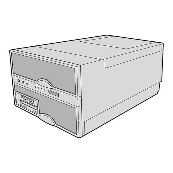
Chapter 1 Introduction to the High-performance Server Chassis Figures 1-2 and 1-3 show the major components of the server. OM07330 Figure 1-2. Chassis, Board Set Front panel board CPU baseboard and processors C. PHP I/O baseboard D. Midplane Memory modules... - Page 23 AC450NX Rack Server System Product Guide OM07349 Figure 1-3. Chassis, Front View 3.5-inch diskette drive (3.5-inch bay) CD-ROM drive (5.25-inch bay) C. Hot-swap bays...
- Page 24 Chapter 1 Introduction to the High-performance Server OM07300 Figure 1-4. Chassis, Rear View PCI and ISA add-in board expansion slots External LVDS connector C. PS/2-compatible keyboard/mouse port, 6-pin D. PS/2-compatible keyboard/mouse port, 6-pin PS/2-compatible serial ports 0 and 1, 9-pin RS-232 connector Super VGA compatible, 15-pin video connector G.
-
Page 25: Controls And Indicators
AC450NX Rack Server System Product Guide Controls and Indicators Item Feature Description Front Panel Power switch When pressed, it turns on or off the DC power inside the server. Reset switch When pressed, it resets the server and causes the power-on self test (POST) to run. - Page 26 Chapter 1 Introduction to the High-performance Server D E F G L K J OM07344 Figure 1-5. Server Controls and Indicators...
-
Page 27: Server Security
AC450NX Rack Server System Product Guide Server Security There are several ways to prevent unauthorized entry or use of the server. Security with the Setup utility: • Set server administrative and user passwords. • Set secure mode to prevent keyboard or mouse input and to prevent use of the front panel controls. -
Page 28: Boot Without Keyboard
Chapter 1 Introduction to the High-performance Server Boot Without Keyboard The server can boot with or without a keyboard. Before it boots, the BIOS displays a message about the keyboard stating whether or not it detects one. During POST, the BIOS automatically detects and tests the keyboard if it is present. - Page 29 Blank page...
-
Page 30: On-Site Installation: Installing The Server
2 On-site Installation: Installing the Server This chapter tells how to: • Select a site • Connect input and output devices • Turn on the server and create installation diskettes from the Server System Configuration Software CD • Read and print a copy of this manual •... -
Page 31: Physical Specifications
AC450NX Rack Server System Product Guide Physical Specifications Height 31.12 cm (12.25 inches) Width 44.45 cm (17.5 inches) Depth 71.12 cm (28.0 inches) Weight 51.4 kg (113 lbs) minimum configuration; 60 kg (132 lbs) maximum configuration Environmental Specifications Temperature –40° to 70 °C (–40° to 158 °F) Nonoperating 5°... -
Page 32: After Unpacking The Server
Chapter 2 On-site Installation: Installing the Server After Unpacking the Server Inspect the shipping box for evidence of mishandling during transit. If the shipping box is damaged, photograph it for reference. After removing the contents, keep the damaged box and the packing materials. - Page 33 AC450NX Rack Server System Product Guide OM07335 Figure 2-1. Server I/O Connections PS/2-compatible keyboard/mouse port, 6-pin connector PS/2-compatible keyboard/mouse port, 6-pin connector C. PS/2-compatible serial port 2 (COM2), 9-pin RS-232 connector D. PS/2-compatible serial port 1 (COM1), 9-pin RS-232 connector...
-
Page 34: Obtaining A Power Cord Set
Chapter 2 On-site Installation: Installing the Server Obtaining a Power Cord Set WARNING Do not attempt to modify or use an AC power cord that is not the exact type required. Because a power cord is not supplied for the server, you must obtain a power cord that meets the following criteria: For North America the cord must be UL Listed/CSA Certified, 14/3, 75 °C type SJT with NEMA 6-15P attachment plug and IEC 320, C19 outlet. - Page 35 AC450NX Rack Server System Product Guide D E F G OM07334 Figure 2-2. Server Power and Reset Switches Power switch Reset switch C. NMI switch D. Power LED (green) Power fault LED (yellow) Cooling fault LED (yellow) G. Drive fault (yellow)
-
Page 36: Power-On Self Test
Chapter 2 On-site Installation: Installing the Server Power-on Self Test Each time you turn on the server the power LED on the front panel turns on and the power-on self test (POST) starts running. POST checks the I/O system board, processor system board, keyboard, and most installed peripheral devices. -
Page 37: Booting From The Server Configuration Software Cd
AC450NX Rack Server System Product Guide Booting From the Server Configuration Software CD CAUTION The Server Configuration Software CD contains only a limited operating system. This limited operating system provides enough function to let you boot from the CD and copy and use the utility and manual files from the CD. -
Page 38: Copying Configuration Software To Diskettes
Chapter 2 On-site Installation: Installing the Server NOTE If you do not see the CD-ROM menu but see the following message instead, Operating system not found you need to change the “Boot Device Priority” to the CD-ROM. See “Server Won’t Boot From the CD” on page 38 for instructions. Copying Configuration Software to Diskettes When you copy software from the CD onto diskettes, device drivers suitable for several different operating systems are copied onto the diskettes. -
Page 39: Server Won't Boot From The Cd
AC450NX Rack Server System Product Guide Server Won’t Boot From the CD It is possible that your server was shipped with the diskette drive or another device set as the first boot device. If so, the server will try to boot from a diskette or other device rather than from the CD we have provided. - Page 40 Chapter 2 On-site Installation: Installing the Server The server should now boot from the CD, displaying a menu bar that includes creating diskettes, diagnostics, reading/printing the manual, and quitting to DOS. CAUTION If the server does not operate as described in this chapter, contact a qualified service technician.
- Page 41 This page should be blank...
-
Page 42: Power-On Self Test: Description/Running
3 Power-on Self Test: Description/Running Power-on Self Test (POST) WARNING The push-button on/off power switch on the front panel of the server does not turn off the AC power. To remove AC power from the server, you must unplug the power cord from the AC inlet filter or wall outlet. Each time you turn on the server the power LED on the front panel turns on and POST starts running. - Page 43 AC450NX Rack Server System Product Guide If POST detects an error, it displays the error code, the server beeps once, and this message appears: Press <F1> to Resume, <F2> for Setup To resume, press <F1>. However, if a drive with bootable media is not detected, the server beeps...
-
Page 44: Setup Utility: When To Run
4 Setup Utility: When to Run The flash-resident BIOS Setup utility is used to configure PHP I/O baseboard resources. It is stored in both flash memory (NVRAM) and the battery-backed memory of the real-time clock (RTC) on the PHP I/O baseboard. When to Run the BIOS Setup Utility The BIOS Setup is a flash-based configuration utility that is used to configure onboard resources and to set user-selectable options such as boot device ordering, keyboard autorepeat, and security. - Page 45 AC450NX Rack Server System Product Guide Each time you turn on or reboot your server POST begins and, after a few seconds, displays this message: Press <F2> to enter Setup After pressing F2, a few seconds may pass before entering Setup while POST completes tests and initialization functions.
-
Page 46: Main Menu
Chapter 4 Setup Utility: When to Run Main Menu Default values are in bold typeface, and auto-configured values are shaded. Feature Option Description System Time HH:MM:SS Set the System Time. To select a field, press <Tab>, <Shift + Tab>, or <Enter>. Then type in a new value. If you replace the battery, the default time is 00:00. - Page 47 AC450NX Rack Server System Product Guide Main Menu (continued) Feature Option Description Type: User User—lets you enter the parameters of the hard disk Auto drive installed at this connection. 1-39 Auto—autotypes the hard disk drive installed here. CD-ROM 1-39—lets you select the predetermined hard disk drive ATAPI Removable installed here.
-
Page 48: Advanced Menu
Chapter 4 Setup Utility: When to Run Main Menu (continued) Feature Option Description Processor 3 Stepping ID, absent or disabled. Processor 4 Stepping ID, absent or disabled. Keyboard Features Press <Enter> for options. Numlock: Auto Select power-on state for numlock. Disabled Key Click: Enabled produces the key click. - Page 49 AC450NX Rack Server System Product Guide Advanced Menu (continued) Feature Option Description Pause Before Boot Disabled Pause five seconds before booting the OS. Enabled PCI Configurations Additional Setup menus to configure PCI devices. PCI Device, Setup items for configuring the specific PCI device.
- Page 50 Chapter 4 Setup Utility: When to Run Advanced Menu (continued) Feature Option Description Serial Port B Disabled Configure serial port B using these options: Enabled • Disabled—no configuration. Auto • Enabled—user configuration. • Auto—BIOS or OS chooses the configuration. • OS Controlled—displayed when controlled by the OS.
- Page 51 AC450NX Rack Server System Product Guide Advanced Menu (continued) Feature Option Description Base RAM Step 1 MB Tests base memory once per MB or once per KB or 1 KB every location. Every location Extended RAM Step 1 MB Tests extended memory once per MB or once per KB or 1 KB every location.
-
Page 52: Security Menu
Chapter 4 Setup Utility: When to Run Security Menu Feature Option Description User Password Is Clear When you enter your user password, this field automatically changes to set. Administrator Clear When you enter your administrator password, this field Password Is automatically changes to set. -
Page 53: Server Menu
AC450NX Rack Server System Product Guide Server Menu Feature Option Description System Management An additional setup menu for changing server management features. Firmware SMIs Disabled Disabled turns off all firmware SMI sources. Enabled System Event Logging Disabled Enabled logs critical system events. - Page 54 Chapter 4 Setup Utility: When to Run Server Menu (continued) Feature Option Description Baud Rate 9600 Select the baud rate. 19.2 K 38.4 K 115.2 K Flow Control No Flow Control Select the flow control. CTS/RTS • CTS/RTS = Hardware XON/XOFF •...
-
Page 55: Boot Menu
AC450NX Rack Server System Product Guide Boot Menu Feature Option Description Disabled Diskette Check: Enabled verifies the diskette type on boot. Disabled Enabled speeds up the boot process. Boot Device Priority Select the search order for the types of boot devices. -
Page 56: Exit Menu Selections
Chapter 4 Setup Utility: When to Run Exit Menu Selections The following menu options are available on the Server menu. Select an option by using the up or down arrow keys. Then press <Enter> to execute the option, and follow the prompts. Option Description Exit Saving Changes... - Page 57 This page is blank...
-
Page 58: System Setup Utility: When To Run
The System Setup Utility (SSU) is on the Server System Configuration Software CD shipped with the server. The SSU provides a graphical user interface (GUI) over an extensible framework for server configuration. For the AC450NX systems, the SSU framework supports the following functions and capabilities: •... -
Page 59: What You Need To Do
AC450NX Rack Server System Product Guide The SSU uses the information provided by .CFG files, configuration registers, flash memory, and the information that you enter, to specify a system configuration. The SSU writes the configuration information to flash memory. The SSU stores configuration values in flash memory. These values take effect when you boot the server. -
Page 60: Starting The Ssu
Chapter 5 System System Setup Utility: When to Run • Running the SSU Remotely To run the SSU remotely, you must invoke the SSU.BAT file with the /t switch and redirect the text-mode output via BIOS console redirection. The /t switch puts the display in text mode and allows the console to be viewed and controlled via BIOS console redirection. -
Page 61: Customizing The Ssu
AC450NX Rack Server System Product Guide Customizing the SSU The SSU lets you customize the user interface according to your preferences. The AF sets these preferences and saves them in the AF.INI file so that they take effect the next time you start the SSU. -
Page 62: Resource Configuration Add-In (Rca) Window
Chapter 5 System System Setup Utility: When to Run Use the tab and arrow keys to highlight the task name, and press the <spacebar> or <Enter>. Figure 5-1. System Setup Utility Main Window Resource Configuration Add-in (RCA) Window The RCA provides three major functions: •... - Page 63 AC450NX Rack Server System Product Guide 1. From the SSU main window, launch the RCA by selecting the Resources task under the RCA heading in the task box. 2. When the RCA window appears, it displays messages similar to the following:...
- Page 64 Chapter 5 System System Setup Utility: When to Run Defining an ISA Card An ISA card usually comes with a vendor-created .CFG file that specifies the resources the card requires to function properly. If the .CFG file is unavailable, you must manually create it or define the card through the SSU.
- Page 65 AC450NX Rack Server System Product Guide Adding and Removing ISA Cards Adding and removing cards through the RCA provides a way for the RCA to run its conflict detection algorithms on the resources requested by the cards. This alerts you to any possible problems with that particular card in the current configuration.
- Page 66 Chapter 5 System System Setup Utility: When to Run Figure 5-4. Configuration Window...
- Page 67 AC450NX Rack Server System Product Guide System Resource Usage Clicking on the Resource Use button in the Configuration window displays the System Resource Usage window. This window shows what resources each device is consuming. This information is useful for choosing resources if a conflict occurs. Devices can be organized according to the resources you want to examine using the options in the Resource section of the screen.
-
Page 68: Multiboot Add-In
Chapter 5 System System Setup Utility: When to Run Multiboot Add-in The Multiboot Add-in (MBA) provides an interface for selecting Initial Program Load (IPL) devices. Using the MBA, you can identify all IPL devices in the system and prioritize their boot order. -
Page 69: Security Add-In
AC450NX Rack Server System Product Guide Security Add-in The Security Add-in (PWA) provides security and password support options. Within the PWA, you can either set or modify the User and Administrator passwords or update any of the various security options available. - Page 70 Chapter 5 System System Setup Utility: When to Run Security Options Under this window, you can set the other security options: • Hot Key—set a key sequence that, when pressed, will drop the server into secure mode. • Lock-Out Timer—set an interval that, if no activity takes place during it, will drop the server into secure mode.
-
Page 71: System Event Log Manager Add-In
AC450NX Rack Server System Product Guide System Event Log Manager Add-in Clicking on the SEL Manger add-in task brings up the SEL Manager window. It lets you examine SEL records: • via the Baseboard Management Controller (BMC) in hex or verbose mode •... -
Page 72: Sensor Data Record (Sdr) Manager Add-In
Chapter 5 System System Setup Utility: When to Run Figure 5-8. System Event Log Main Window Sensor Data Record (SDR) Manager Add-In In this window, you can: • Examine all SDR records through the BMC (in either Hex or Verbose mode) •... - Page 73 AC450NX Rack Server System Product Guide Menu Click On File Open FRU Opens FRU data from a previously saved file Save SDR Saves SDR data to a file in binary raw or verbose text format Exit Quits the SDR Manager...
-
Page 74: Field Replaceable Unit (Fru) Manager
Chapter 5 System System Setup Utility: When to Run Field Replaceable Unit (FRU) Manager In this window you can: • Examine all FRU Inventory areas on the server (in either Hex or Verbose mode) • Examine individual FRU Inventory areas (in either Hex or Verbose mode) •... -
Page 75: Exiting The Ssu
AC450NX Rack Server System Product Guide Figure 5-10. FRU Manager Main Window Exiting the SSU Exiting the SSU causes all windows to close. 1. Exit the SSU by opening the menu bar item File in the SSU Main window. See “System Setup Utility Main Window”... -
Page 76: Scsi Configuration Utility
6 SCSI Configuration Utility The SCSI configuration utility allows you to configure/view the settings of the host adapters and devices in the server. For information about the SCSI Configuration Utility refer to the PCI SCSI Device Manager System Users Guide. -
Page 78: Emergency Management Port Console: How To Use
Powering the server on or off • Resetting the server The EMP Console uses three management plug-ins to monitor the server: • SEL Viewer (not available on AC450NX servers) • SDR Viewer (not available on AC450NX servers) • FRU Viewer The EMP Console also has a Phonebook plug-in that can be used to create and maintain a list of servers and their phone numbers. -
Page 79: How Emp Console Works
AC450NX Rack Server System Product Guide How EMP Console Works The EMP shares use of the COM 2 port with the system on the server. When the EMP has control of the port, the port operates in command mode. When the system has control, the port operates in console redirect mode. -
Page 80: Emp Console Access Modes (Server Configured For Console Redirection)
Chapter 7 Emergency Management Port Console: How to Use Figure 7-2. EMP Console in Redirect State Figure 7-2 shows the EMP Console window in redirect mode with the terminal window. The text that appears on the server monitor displays in the Redirect window. Availability of the various EMP Console features are determined by two factors: the BIOS EMP access mode and whether the server’s COM 2 port is configured for console redirection. -
Page 81: Requirements
AC450NX Rack Server System Product Guide Table 7-2. EMP Console Access Modes (Server not configured for console redirection) Mode Server is powered off During POST After OS boots Disabled Redirect window appears, Redirect window appears, Redirect window appears, but is blank... -
Page 82: Setting Up The Server For The Emp
Chapter 7 Emergency Management Port Console: How to Use Setting Up the Server for the EMP To use the EMP, you must configure the server’s BIOS with specific settings. These settings are found in the BIOS Server menu and the Console Redirection submenu. The BIOS settings section, found earlier in this document, shows all the available options. -
Page 83: Main Emp Console Window
Disconnects from the currently connected server. Displays the Power On/Off dialog. Displays the Reset dialog. Launches the SEL Viewer. ( not available on AC450NX servers ) Launches the SDR Viewer. ( not available on AC450NX servers ) Launches the FRU Viewer. -
Page 84: Emp Console Main Menu
Power On/Off - displays the Power on/off dialog. Reset - displays the Reset dialog. SEL Viewer - displays the SEL Viewer. (not available on AC450NX servers) SDR Viewer - displays the SDR Viewer. (not available on AC450NX servers) ... -
Page 85: Server Control Operations
AC450NX Rack Server System Product Guide Server Control Operations Three server control operations are available from the menu or toolbar in EMP Console: remote server connection, powering the server on and off, and resetting the server. The server console mode can also be switched between EMP active and BIOS redirect modes through post-power-up and reset options. -
Page 86: Power On/Off
Chapter 7 Emergency Management Port Console: How to Use • Config - displays the Phonebook dialog. • Cancel - exits the Connect dialog without taking any action. • Help - displays the help information for this dialog. Power On/Off Selecting Power On/Off from the Action menu displays the Power on/off dialog. This dialog provides commands to remotely power on or power off the server. -
Page 87: Reset
AC450NX Rack Server System Product Guide Reset Selecting Reset from the Action menu displays the Reset dialog. This dialog provides the ability to remotely reset the server with post-reset options. Figure 7-5. Reset Dialog Options available in the dialog are: •... -
Page 88: Phonebook
Chapter 7 Emergency Management Port Console: How to Use Phonebook EMP Console provides a support plug-in known as Phonebook. It stores names and numbers of servers in a list that can be updated by adding, modifying or deleting entries. Phonebook can be opened from the main menu and toolbar, or launched from the Connect dialog by clicking the Config button. -
Page 89: Fru Viewer
AC450NX Rack Server System Product Guide FRU Viewer The FRU Viewer allows you to view the server’s FRU (Field Replaceable Unit) data from the server’s Front Panel FRU information area. The options available in the FRU Viewer are: • View all FRU records •... -
Page 90: Fru And Sdr Load Utility: When To Run
8 FRU and SDR Load Utility: When to Run The Field Replacement Unit (FRU) and Sensor Data Record (SDR) Load Utility is a DOS based program used to update the server management subsystem’s product level FRU, SDR, and the Desktop Management Interface (DMI) nonvolatile storage components (EEPROMs). The load utility: •... -
Page 91: How You Use The Frusdr Load Utility
AC450NX Rack Server System Product Guide How You Use the FRUSDR Load Utility This utility is compatible with ROM-DOS Ver. 6.22, MS-DOS Ver. 6.22, and later versions. The utility accepts CFG, SDR and FRU load files. The executable file for the utility is frusdr.exe. The utility requires the following supporting files: •... - Page 92 Chapter 8 FRU and SDR Load Utility: When to Run Copyright (c) 1998, Intel Corporation, All Rights Reserved This utility must be run from a system executing DOS. Running in a Window’s DOS box is insufficient and will provide incorrect results. Programming the BMC FRU area clears the SDR table, therefore the SDR table must be reprogrammed.
-
Page 93: Displaying A Given Area
AC450NX Rack Server System Product Guide Displaying a Given Area When the utility is run with the -d DMI, -d FRU, or -d SDR command line flag, the indicated area is displayed. Each area represents a sensor; one sensor for each instrumented device in the server. - Page 94 Board Information Area (Version 1, Length 64) Unicode Country Base = 00h Manufacturing Time (mins) = 733803 Manufacturer Name (ASCII) = Intel Product Name (ASCII) = AC450NX Server System Serial Number (ASCII) = 0123456789 Part Number (ASCII) = 664653-001 END OF FIELDS CODE...
- Page 95 AC450NX Rack Server System Product Guide Product Information Area (Version 1, Length 80) Unicode Country Base = 00h Manufacturer Name (ASCII) = Intel Product Name (ASCII) = AC450NX Server System Part Number (ASCII) = ASDK128M1P2MBPP Version (ASCII) Serial Number (ASCII)
-
Page 96: Using Specified Cfg File
Chapter 8 FRU and SDR Load Utility: When to Run Using Specified CFG File The utility can be run with the command line parameter of -cfg filename.cfg. The filename can be any DOS accepted, eight-character filename string. The utility loads the specified CFG file and uses the entries in the configuration file to probe the hardware and to select the proper SDRs to load into nonvolatile storage. - Page 97 AC450NX Rack Server System Product Guide Updating DMI Nonvolatile Storage Area After programming the BMC FRU area, the utility then programs the following Chassis, Board, and Product FRU information to the DMI fields. Example: Loading DMI System Area Manufacturer Name : Intel...
-
Page 98: Hot-Swappable Fans: Hot Swapping
9 Hot-swappable Fans: Hot Swapping This chapter tells how to hot-swap a fan. When the yellow fan failure LED on the front panel turns on, you can determine which fan is defective by checking the yellow fan failure LEDs mounted next to each fan. When a fan fails, the LED will be on continuously. -
Page 99: Hot-Swapping A Fan
AC450NX Rack Server System Product Guide Hot-Swapping a Fan The server contains six fans in a (5 + 1) redundant configuration for cooling system components. If a single fan fails, the yellow fan failure LED on the front panel turns on. A fan-fail LED mounted next to each fan identifies the failed fan. - Page 100 Chapter 9 Hot-swappable Fans: Hot Swapping OM07304 Figure 9-1. Removing/Hot-swapping a Fan Grasp holes...
-
Page 101: Replacing A Fan
AC450NX Rack Server System Product Guide Replacing a Fan See Figure 9-1. 1. Remove the new fan from the protective packaging. 2. Record the model and serial numbers of the fan in your equipment log. NOTE Fans are keyed and can only be inserted one way. Be sure that the fan connector will mate with the front panel baseboard connector when aligning the fan in the fan cavity. -
Page 102: Hot-Swappable Scsi Hard Disk Drives: Installing/Hot Swapping
10 Hot-swappable SCSI Hard Disk Drives: Installing/Hot Swapping Hot-docking Bays Two 3.5-inch hot-docking bays provide space for 3.5-inch wide by 1-inch high single connector attachment (SCA) SCSI hard disk drives. You can install up to 2 industry-standard wide/fast-20 SCSI III SCA-type hard disk drives in these bays. The power supply fans provide cooling for the hot swap drives. -
Page 103: Scsi Sca Hard Disk Drives
AC450NX Rack Server System Product Guide SCSI SCA Hard Disk Drives The server supports a variety of single-ended and differential SCSI SCA-type hard disk drives. As shipped from the supplier, the server may not contain any drives. Contact your sales representative or dealer for a list of approved drives that can be installed in the server. - Page 104 Chapter 10 Hot-swappable SCSI Hard Disk Drives: Installing/Hotswapping OM07153 Figure 10-1. Hard Disk Drive and Carrier EMI/ESD grounding clips and fingers SCA connector C. SCSI hard disk drive D. Drive carrier handle OM08268 Figure 10-2. Hard Disk Drive and Carrier Assembly Four screws...
-
Page 105: Installing A Scsi Sca Hard Disk Drive In A Hot-Docking Bay
AC450NX Rack Server System Product Guide Installing a SCSI SCA Hard Disk Drive in a Hot-docking Bay See Figure 10-3. 1. Orient the carrier and drive assembly in front of the hot-docking bay guide rails so that metal fingers of the perforated metal bracket attached to the carrier are facing up. Make sure that the carrier is placed correctly into the guide rails to avoid damage. - Page 106 Chapter 10 Hot-swappable SCSI Hard Disk Drives: Installing/Hotswapping OM07336 Figure 10-3. Installing a Hard Disk Drive Drive carrier latch Drive carrier handle C. Hot-docking bay guide rails 3. If you installed a RAID controller board in your server, run the Disk Array Controller Configuration utility supplied with the board.
-
Page 107: Hot-Swapping A Scsi Sca Hard Disk Drive
AC450NX Rack Server System Product Guide Hot-swapping a SCSI SCA Hard Disk Drive Status LEDs are arranged in sets of three below each of the 2 hot-docking bays. They monitor the status of each drive. When a yellow LED is on continuously, it is okay to hot-swap (remove and replace) a bad drive with a good one. - Page 108 Chapter 10 Hot-swappable SCSI Hard Disk Drives: Installing/Hotswapping A B C OM07345 Figure 10-4. Hot-swap SCSI Drive Indicators Green LED, drive power Green LED, drive activity C. Yellow LED, drive fault W page should be blank...
-
Page 110: Hot-Swappable Power Supplies: Hot Swapping
11 Hot-swappable Power Supplies: Hot Swapping This chapter tells how to hot-swap a server power supply. When the yellow power supply failure LED on the front panel turns on, you can determine which power supply is defective by checking the three status LEDs on the back of each power supply. If a power supply fails, the yellow FAIL LED on the back of the power supply will be on continuously. -
Page 111: Hot Swapping A Power Supply
AC450NX Rack Server System Product Guide Hot Swapping a Power Supply In a fully configured server, the power system contains three 750 watt auto-ranging power supplies; one of the power supplies is redundant. If a single power supply fails in the redundant power system, the yellow power supply failure LED on the front panel turns on. - Page 112 Chapter 11 Hot-swappable Power Supplies: Hot Swapping OM07324 Figure 11-1. Removing a Power Supply Pull down handle Remove power supply...
-
Page 113: Replacing A Power Supply
AC450NX Rack Server System Product Guide Replacing a Power Supply See Figure 11-1. 1. Remove the new power supply from the protective packaging. 2. Record the model and serial numbers of the power supply in your equipment log. 3. Slide the replacement power supply into the power supply cavity with the handle out. -
Page 114: Part Ii: Service Technician's Guide
Part II: Service Technician’s Guide Safety Guidelines 12 Server Covers: Removing/Reinstalling 13 Server Components: Removing/Reinstalling 14 Removable Media Drives: Installing/Removing/Replacing 15 Midplane: Description/Voltages 16 Peripheral Bay Backplane: Description 17 PHP I/O Baseboard: Description/Setting Configuration Jumpers 18 CPU Baseboard: Description/Setting Configuration Jumpers 19 Memory Modules: Description/Adding Memory 20 Power System: Description/Calculating Power Usage 21 Back-up Battery: Replacing/Disposing... -
Page 116: Safety Guidelines
Safety Guidelines EFORE YOU REMOVE SERVER COVERS OBSERVE THESE GUIDELINES 1. Turn off all peripheral devices connected to the server. 2. Turn off DC power in the server by pressing the push-button on/off power switch on the front panel of the server. 3. -
Page 117: Equipment Rack Precautions
AC450NX Rack Server System Product Guide CAUTION Electrostatic discharge (ESD) and ESD protection: ESD can damage disk drives, add-in boards, and other components. This server can withstand normal levels of environmental ESD while you are hot-swapping hard disk drives and power supplies. However, we recommend doing all procedures in this manual only at an ESD workstation. - Page 118 Safety Guidelines Grounding the rack installation: To avoid the potential for an electrical shock hazard, you must include a third wire safety grounding conductor with the rack installation. If the server power cord is plugged into an AC outlet that is part of the rack, then you must provide proper grounding for the rack itself.
-
Page 120: 12 Server Covers: Removing/Reinstalling
12 Server Covers: Removing/Reinstalling This chapter tells how to remove and reinstall the server covers. Warnings and Cautions Only a qualified service technician is authorized to remove the server covers and to access any of the components inside the server. Before removing the covers, see “Safety Guidelines” on page 115. -
Page 121: Removing The Peripheral Bay Cover
AC450NX Rack Server System Product Guide OM07302 Figure 12-1. Server Covers Memory module cover Fan array cover C. Top cover D. PCI hot-plug cover Removing the Peripheral Bay Cover The peripheral bay cover is attached to the chassis with press-in rivets and spring clips. See Figure 12-2. -
Page 122: Removing The Front Bezel
Chapter 12 Server Covers: Removing/Reinstalling OM07356 Figure 12-2. Peripheral Bay Cover and Front Bezel Plastic snap-on Peripheral Bay Cover Plastic snap-on Front Bezel Removing the Front Bezel The plastic front bezel is attached to the chassis with press-in rivets and spring clips in the same manner as the peripheral bay cover. - Page 123 AC450NX Rack Server System Product Guide 6. Remove and save the screws that attach the top cover to the chassis. NOTE It is not necessary to remove the PCI bus hot-plug cover. 7. While facing the back of the server, pull hard on the front edge of the cover to disengage the tabs along the sides of the cover from the slots in the chassis slide.
-
Page 124: Reinstalling The Top Cover
Chapter 12 Server Covers: Removing/Reinstalling OM07305 Figure 12-4. PCI Regular Slot Cover Two screws Reinstalling the Top Cover See Figures 12-3 and 12-4. 1. Reinstall the PCI bus regular expansion slot cover. 2. While facing the back of the server, position the top cover over the chassis so that the tabs along the edges of the cover align with the slots in the top edge of the chassis. -
Page 125: Reinstalling The Pci Bus Hot-Plug Cover
AC450NX Rack Server System Product Guide OM07357 Figure 12-5. PCI Bus Hot-Plug Cover Reinstalling the PCI Bus Hot-Plug Cover See Figure 12-5. 1. Ensure that add-in boards are firmly seated in their respective slots. 2. Position the cover over the top cover so that the tabs along its edges align with the slots in the top cover. -
Page 126: Removing The Fan Array Assembly Cover
Chapter 12 Server Covers: Removing/Reinstalling Removing the Fan Array Assembly Cover 1. Observe the precautions on page 115, “Safety Guidelines.” 2. Remove the front bezel as described earlier. 3. Remove the top cover as described earlier. 4. Remove and save the screw that secures the fan array assembly cover to the chassis. 5. -
Page 127: Reinstalling The Memory Module Cover
AC450NX Rack Server System Product Guide OM07353 Figure 12-6. Memory Module Cover Reinstalling the Memory Module Cover See Figure 12-6. 1. Observe the precautions on page 115, “Safety Guidelines.” 2. Place the cover in position and tighten the four captive screws to secure the cover. -
Page 128: 13 Server Components: Removing/Reinstalling
13 Server Components: Removing/Reinstalling This chapter tells how to remove and reinstall major server components. Because the CPU baseboard is mounted horizontally toward the front of the chassis and the PHP I/O baseboard is mounted horizontally towards the rear of the chassis, the procedures start with the covers and end up with the baseboards. -
Page 129: Fan Array Housing
AC450NX Rack Server System Product Guide Fan Array Housing Removing the Fan Array Housing See Figures 13-1 and 13-2. 1. Observe the precautions on page 115, “Safety Guidelines.” 2. Remove the top cover, the fan array assembly cover, and the memory module cover as described in Chapter 12, “Server Covers: Removing/Reinstalling.”... - Page 130 Chapter 13 Server Components: Removing/Reinstalling OM07304 Figure 13-1. Fan Removal...
- Page 131 AC450NX Rack Server System Product Guide OM07308 Figure 13-2. Fan Array Housing Screws (five) Fan array housing...
-
Page 132: Lcd Module
Chapter 13 Server Components: Removing/Reinstalling LCD Module The LCD module displays server information. Removing the LCD Module See Figure 13-3. 1. Observe the precautions on page 115, “Safety Guidelines.” 2. Remove the memory module cover as described in Chapter 12, “Server Covers: Removing/Reinstalling.”... -
Page 133: Memory Modules
AC450NX Rack Server System Product Guide OM07358 Figure 13-3. LCD Module Memory Modules CAUTION To avoid damaging the memory module DIMM sockets, do not attempt to use the metal stiffener on the memory module as a handle. Removing a Memory Module See Figure 13-4. -
Page 134: Reinstalling A Memory Module
Chapter 13 Server Components: Removing/Reinstalling Reinstalling a Memory Module See Figure 13-4. 1. Observe the precautions on page 115, “Safety Guidelines.” 2. Being careful not to touch the components on the memory module, remove it from its protective wrapper. Place the module DIMM-side up on a nonconductive, static-free surface. 3. - Page 135 AC450NX Rack Server System Product Guide OM07361 Figure 13-4. Memory Module...
-
Page 136: Front Side Bus Terminator Module
Chapter 13 Server Components: Removing/Reinstalling Front Side Bus Terminator Module The CPU baseboard provides four slot 2 connectors for processors packaged in S.E.C. cartridges. If any slot 2 connector is depopulated, a terminator module must be installed in the connector to properly terminate the signals on the front side bus (FSB). - Page 137 AC450NX Rack Server System Product Guide OM07306 Figure 13-5. Removing a Holddown...
-
Page 138: Processor
Chapter 13 Server Components: Removing/Reinstalling Processor The CPU baseboard supports up to four processors packaged in S.E.C. cartridges. CAUTION The processors can be extremely sensitive to ESD and always require careful handling. After removing a processor from a protective wrapper or from the CPU baseboard, place it on a nonconductive, static-free surface. -
Page 139: Dc To Dc Converter Vrm
AC450NX Rack Server System Product Guide DC to DC Converter VRM VRM in connector Provides power for Description Processor #1 Processor core power only Processor #1 and #2 L2 Cache power only Processor #2 Processor core power only Processor #3... - Page 140 Chapter 13 Server Components: Removing/Reinstalling OM07318 Figure 13-6. DC to DC Converter VRM VRM socket DC to DC Converter VRM C. Ejector lever D. J1, VRM connector J3, VRM connector J2, VRM connector G. J5, VRM connector H. J6, VRM connector J4, VRM connector CPU Baseboard...
-
Page 141: Cpu Tray
AC450NX Rack Server System Product Guide CPU Tray The CPU tray provides rigid mounting for the front panel board, the CPU baseboard, and the memory modules. It also facilitates mating with the midplane. Removing the CPU Tray See Figure 13-7. - Page 142 Chapter 13 Server Components: Removing/Reinstalling OM07327 Figure 13-7. CPU Tray Rear support Eject/Insert levers C. Screws (six) D. Midplane Grand connector Front panel board...
-
Page 143: Front Panel Board
AC450NX Rack Server System Product Guide OM07328 Figure 13-8. CPU Tray Support Rail Front Panel Board The front panel board contains the server controls and indicators. It is mounted on snap-on and threaded standoffs on the CPU Tray (see Figure 13-7). -
Page 144: Reinstalling The Front Panel Board
Chapter 13 Server Components: Removing/Reinstalling CAUTION When the front panel board is free of the CPU board connector, its switches are surrounded by sheet metal. Be careful not to damage these switches when lifting the front panel board. 5. Push/pull the front panel board horizontally to free it from the CPU baseboard connector and lift the board from the chassis. -
Page 145: Cpu Baseboard
AC450NX Rack Server System Product Guide CPU Baseboard Removing the CPU Baseboard See Figure 13-10. 1. Observe the precautions on page 115, “Safety Guidelines.” 2. Remove the CPU tray as described earlier. 3. Remove the front panel board as described earlier. - Page 146 Chapter 13 Server Components: Removing/Reinstalling OM07321 Figure 13-10. CPU Baseboard Standoff (six) Screw (twelve)
-
Page 147: Add-In Boards
AC450NX Rack Server System Product Guide Add-in Boards The PHP I/O baseboard provides 10 PCI bus master slots and one ISA bus master slot. They † accept any add-in PCI and ISA boards or any add-in board that is compatible with an IBM PC AT †... - Page 148 Chapter 13 Server Components: Removing/Reinstalling OM07319 Figure 13-11. PHP I/O Baseboard Expansion Slots 16-bit ISA slot 32-bit PCI slots C. 64-bit hot swap PCI slots OM07337 Figure 13-12. Expansion Slot Cover...
- Page 149 AC450NX Rack Server System Product Guide 5. Being careful not to touch the components or gold edge connectors on the add-in board, remove it from the protective wrapper, and place it component-side up on a nonconductive, antistatic surface. 6. Record the serial number of the board in your equipment log.
-
Page 150: Removing An Add-In Board
Chapter 13 Server Components: Removing/Reinstalling Removing an Add-in Board CAUTION Expansion slot covers must be installed on all vacant slots to maintain the electromagnetic emission characteristics of the server and to ensure proper cooling of the server components. See Figures 13-11, 13-12, and 13-13. 1. -
Page 151: I/O Riser Card
AC450NX Rack Server System Product Guide I/O Riser Card Removing the I/O Riser Card See Figure 13-14. 1. Observe the precautions on page 115, “Safety Guidelines.” 2. Remove the top and PCI bus regular slot covers as described in Chapter 12, “Server Covers: Removing/Reinstalling.”... - Page 152 Chapter 13 Server Components: Removing/Reinstalling OM07323 Figure 13-14. I/O Riser Card J1B1, I/O connector Screw C. ICMB signal cable...
-
Page 153: I/O Tray
AC450NX Rack Server System Product Guide I/O Tray The I/O Tray provides rigid mounting for the PHP I/O baseboard and facilitates mating with the midplane. Removing the I/O Tray See Figure 13-15. 1. Observe the precautions on page 115, “Safety Guidelines.”... - Page 154 Chapter 13 Server Components: Removing/Reinstalling OM07310 Figure 13-15. I/O Tray Screws (three) Eject/insert levers C. I/O Tray...
-
Page 155: Intelligent Chassis Management Bus (Icmb) Board
AC450NX Rack Server System Product Guide Intelligent Chassis Management Bus (ICMB) Board Removing the ICMB Board See Figure 13-16. 1. Observe the precautions on page 115, “Safety Guidelines.” 2. Remove the top and PCI bus regular slot covers as described in Chapter 12, “Server Covers: Removing/Reinstalling.”... - Page 156 Chapter 13 Server Components: Removing/Reinstalling OM07354 Figure 13-16. ICMB Board...
-
Page 157: Php I/O Baseboard
AC450NX Rack Server System Product Guide PHP I/O Baseboard CAUTION The PHP I/O baseboard can be extremely sensitive to ESD and always requires careful handling. After removing the baseboard from the server, place it component-side up on a nonconductive, static-free surface to prevent shorting out the battery leads. - Page 158 Chapter 13 Server Components: Removing/Reinstalling 12. Reinstall all PCI hot plug expansion slot power switch activators and covers in their original positions. 13. Reinstall the top and PCI bus regular slot covers as described in Chapter 12. 14. Connect all peripheral device cables that go to the I/O panel on the rear of the system. 15.
-
Page 159: Midplane
AC450NX Rack Server System Product Guide MidPlane Removing the Midplane 1. Observe the precautions on page 115, “Safety Guidelines.” 2. Remove the top and PCI bus regular slot covers as described in Chapter 12, “Server Covers: Removing/Reinstalling.” 3. Remove the CPU tray as described earlier. -
Page 160: Reinstalling The Ac Filter And Cable
Chapter 13 Server Components: Removing/Reinstalling Reinstalling the AC Filter and Cable 1. Remove the AC filter and cable from the antistatic protective wrapper if you placed it in one. 2. Lay the cable in position inside the chassis. 3. Reinstall the three plug retaining brackets and secure with screws. 4. -
Page 161: Peripheral Bay Backplane
AC450NX Rack Server System Product Guide OM07350 Figure 13-18. Peripheral Bay Peripheral Bay Backplane Removing the Peripheral Bay Backplane See Figure 13-19. 1. Observe the precautions on page 115, “Safety Guidelines.” 2. Remove the top cover as described in Chapter 12, “Server Covers: Removing/Reinstalling.”... -
Page 162: Reinstalling The Peripheral Bay Backplane
Chapter 13 Server Components: Removing/Reinstalling Reinstalling the Peripheral Bay Backplane See Figure 13-19. 1. Observe the precautions on page 115, “Safety Guidelines.” 2. Remove the board from the antistatic protective wrapper if you placed it in one. 3. Position and align the board over the two alignment pins. 4. -
Page 163: Peripheral Bay Blindmate Board
AC450NX Rack Server System Product Guide Peripheral Bay Blindmate Board Removing the Peripheral Bay Blindmate Board 1. Observe the precautions on page 115, “Safety Guidelines.” 2. Remove the top cover as described in Chapter 12, “Server Covers: Removing/Reinstalling.” 3. Remove the fan array housing as described earlier. - Page 164 Chapter 13 Server Components: Removing/Reinstalling OM07342 Figure 13-20. Peripheral Bay Blind Mate Board Screw (four) This page is blank...
-
Page 166: Removable Media Drives: Installing/Removing/Replacing
14 Removable Media Drives: Installing/Removing/Replacing This chapter tells how to remove and reinstall removable media drives. Warnings and Cautions Only a qualified service technician is authorized to remove the server covers and to access any of the components inside the server. Before removing the covers, see “Safety Guidelines” on page 115. -
Page 167: Removing The Diskette Drive
AC450NX Rack Server System Product Guide Removing the Diskette Drive See Figure 14-1. 1. Observe the precautions on page 115, “Safety Guidelines.” 2. Remove the peripheral bay as described in Chapter 13, “Server Components: Removing/Reinstalling.” 3. Disconnect the power and signal cables from the 3.5-inch diskette drive. - Page 168 Chapter 14 Removable Media Drives: Installing/Removing/Replacing OM07360 Figure 14-1. Diskette Drive Screw (one)
-
Page 169: Cd-Rom Drive
AC450NX Rack Server System Product Guide CD-ROM Drive The server comes with an CD-ROM drive installed in the peripheral bay. Contact your sales representative or dealer for a list of approved add-in devices. Removing the CD-ROM Drive See Figures 14-2, and 14-3. - Page 170 Chapter 14 Removable Media Drives: Installing/Removing/Replacing OM07359 Figure 14-2. CD-ROM Drive CD-ROM Drive Plastic snap-in slide rail C. Tab D. Power cable Signal cable...
-
Page 171: Replacing The Cd-Rom Drive
AC450NX Rack Server System Product Guide OM06742 Figure 14-3. Snap-in Plastic Slide Rails CD-ROM drive C. Screw D. Slide rail Replacing the CD-ROM Drive See Figures 14-2, and 14-3. 1. Remove the CD-ROM drive from the protective packaging, and place it on an antistatic surface. -
Page 172: 15 Midplane: Description/Voltages
15 Midplane: Description/Voltages This chapter describes the midplane. Warnings and Cautions Only a qualified service technician is authorized to remove the server covers and to access any of the components inside the server. Before removing the covers, see “Safety Guidelines” on page 115. -
Page 173: Detection Signals
AC450NX Rack Server System Product Guide Detection Signals Signal Name Description Present When the presence detect line is low, the power supply is present. AC OK When the power-good signal on the midplane goes high, it signifies that all power supply voltages are available and stable. -
Page 174: Midplane Connectors
Chapter 15 Midplane: Description/Voltages Midplane Connectors OM07339 Figure 15-1. Midplane Grand connector Memory module connector (J6) C. Peripheral power connector (J11) D. Memory module connector (J7) -
Page 175: Grand Connector
AC450NX Rack Server System Product Guide Grand Connector Pins on this connector extend through the midplane and connect with both the CPU baseboard and the PHP I/O baseboard. F16 and Front Panel Connector, J3 Signals Pins COM2_TO_FP_EN GROUND GROUND COM2_TO_SIO_EN... - Page 176 Chapter 15 Midplane: Description/Voltages F16 and Front Panel Connector, J3 (continued) Signals Pins X1D_L(0) GROUND GROUND FP_NMI_SWT_L PWR_CNTRL_SFC_L X1D_L(1) X1XRTS_L X1HRTS_L GROUND GROUND X1D_L(3) GROUND GROUND PWR_CNTRL_RTC_L I2C_CEL_CONNECT_FPC X1D_L(4) X1D_L(2) X1BE_L(0) GROUND GROUND GROUND GROUND GROUND X1BLK_L I2C_CEL_CONNECT_BMC X1D_L(6) X1D_L(5) X1PAR_L GROUND GROUND...
- Page 177 AC450NX Rack Server System Product Guide Grand Connector to Mem A, J4 and Mem B, J1 Signals Pins MD#(35) MD#(34) MD#(33) MD#(32) MD#(31) +1.5V MD#(30) DSTBN1# MD#(29) MD#(28) MD#(27) MD#(26) DSTBP1# MD#(25) MD#(24) MD#(23) +1.5V MD#(22) MD#(21) MD#(20) MD#(19) MUXCLK0...
-
Page 178: Grand Connector Power Module 1 Connector J2
Chapter 15 Midplane: Description/Voltages Grand Connector to Mem A, J4 and Mem B, J1 (continued) Signals Pins MD#(62) MD#(61) MD#(60) DSTBP3# MD#(59) MD#(58) MUXCLK1 MD#(56) MD#(57) MD#(55) MD#(54) Unused Was DCMPLT# Was DVALID# Was WDEVT# +1.5V MD#(53) MD#(52) MD#(51) MD#(50) MD#(49) MD#(48) DSTBP2#... -
Page 179: Grand Connector Power Module 2 Connector J5
AC450NX Rack Server System Product Guide Grand Connector Power Module 2 Connector J5 Signals Pins P1X1 3.3V P1X2 3.3V P1X3 3.3V P2X1 3.3V P2X2 3.3V P2X3 3.3V P1X1 P1X2 P1X3 P2X1 P2X2 P2X3 P1X1 P1X2 P1X3 P2X1 P2X2 P2X3... - Page 180 Chapter 15 Midplane: Description/Voltages Memory Board 1 & 2 Interface Connector J6 & J7 Signals Pins MD#(36) MD#(37) +3.3V GDCMPLT# +3.3V DSTBN2# MD#(38) MD#(39) MD#(40) +3.3V MD#(41) +3.3V DSTBP2# MD#(42) MD#(43) MD#(44) +3.3V MD#(45) +3.3V MD#(46) MD#(47) MD#(48) MD#(49) +3.3V MD#(50) +3.3V MD#(51)
-
Page 181: Memory Board 1 & 2 Interface Connector J6 & J7
AC450NX Rack Server System Product Guide Memory Board 1 & 2 Interface Connector J6 & J7 (continued) Signals Pins +1.5V +3.3V +3.3V +1.5V TRST# +3.3V SPARECLK0 +1.5V +3.3V MD#(0) +3.3V MD#(1) MD#(2) MD#(3) MD#(4) +3.3V MD#(5) +3.3V DSTBN0# MD#(6) MD#(7) MD#(8) +3.3V... -
Page 182: Power Supply Connectors J8, J9, & J10
Chapter 15 Midplane: Description/Voltages Power Supply Connectors J8, J9, & J10 Signal (Description) Signal (Description) Signal (Description) VCC12 VCC12 VCC12 VCC12 VCC12 PRED_FAIL_PSxl M12V (-12V) VBIAS (+24V) PSx_SCL (I²C SCL) PSx_SDA (I²C SDA) 12V_SENSE PGOOD (AC OK) PSx_FAULT (12V Rem.Sense) VCC5STBY P5V_LS (5V Load Share) P3_3V_LS... -
Page 184: 16 Peripheral Bay Backplane: Description
16 Peripheral Bay Backplane: Description This chapter describes the peripheral bay backplane and lists its SCSI ID. Warnings and Cautions Only a qualified service technician is authorized to remove the server covers and to access any of the components inside the server. Before removing the covers, see “Safety Guidelines” on page 115. -
Page 185: Scsi Id Configurations
AC450NX Rack Server System Product Guide then applies power to the drive. Power control also lets you insert and store a spare drive in an SCA connector. When a drive fails, the spare drive can be put into service. SCSI ID Configurations The SCSI chip on the peripheral bay backplane uses the SAF-TE protocol to communicate with the I/O baseboard and uses SCSI ID 6. - Page 186 White text...
-
Page 187: Php I/O Baseboard: Description/Setting Configuration Jumpers
17 PHP I/O Baseboard: Description/Setting Configuration Jumpers This chapter describes the PHP I/O baseboard and tells how to configure the jumpers. Warnings and Cautions Only a qualified service technician is authorized to remove the server covers and to access any of the components inside the server. -
Page 188: 32-Bit Pci Expansion Slots
AC450NX Rack Server System Product Guide 32-bit PCI Expansion Slots Six 32-bit PCI bus master slots (two primary and four secondary) on the PHP I/O baseboard provide expansion enhancement. One 32-bit primary slot shares a common chassis expansion slot with the ISA slot; you can use the shared slot for either PCI or ISA but not both. The PCI bus operates at 33 MHz and provides: •... -
Page 189: Pci Video Controller
Chapter 17 PHP I/O Baseboard: Description/Setting Configuration Jumpers PCI Video Controller The onboard Cirrus Logic GD5446 PCI VisualMedia accelerator is a 64-bit DRAM-based SVGA controller with hardware-accelerated BitBLT transfers of data, video playback, and video capture to the frame buffer. The frame buffer is addressable through a 16-Mbyte window consisting of three, 4-Mbyte byte-swapping apertures, and a special video aperture. - Page 190 AC450NX Rack Server System Product Guide Extended VGA Modes Colors Pixel Horiz. Vert. Mode(s) (number/ Char. x Char. Freq. Freq. Freq. in Hex palette size) Cell Resolution (MHz) (KHz) (Hz) 58, 6A 16/256K 100 x 37 800 X 600 35.2...
- Page 191 Chapter 17 PHP I/O Baseboard: Description/Setting Configuration Jumpers Extended VGA Modes (continued) Colors Pixel Horiz. Vert. Mode(s) (number/ Char. x Char. Freq. Freq. Freq. in Hex palette size) Cell Resolution (MHz) (KHz) (Hz) ‡ 640 X 480 31.5 37.5 ‡ 640 X 480 43.3 ‡...
-
Page 192: Symbios 53C896 Scsi Controller
AC450NX Rack Server System Product Guide Extended VGA Modes (continued) Colors Pixel Horiz. Vert. Mode(s) (number/ Char. x Char. Freq. Freq. Freq. in Hex palette size) Cell Resolution (MHz) (KHz) (Hz) 1024 x 768 1024 x 768 78.7 1024 x 768 94.5... - Page 193 Chapter 17 PHP I/O Baseboard: Description/Setting Configuration Jumpers Front Panel Controller (FPC) Where located: on the front panel board What it manages: • server power control consolidation from several sources push-button power signal from the front panel connector real-time clock (RTC) ...
-
Page 194: I/O Riser Card
AC450NX Rack Server System Product Guide I/O Riser Card The I/O riser card contains all the legacy I/O connections such as video, keyboard, mouse, etc. The card plugs into the legacy connector on the PHP I/O baseboard and provides the following external connectors: •... -
Page 195: Php I/O Baseboard Configuration Jumpers
Chapter 17 PHP I/O Baseboard: Description/Setting Configuration Jumpers PHP I/O Baseboard Configuration Jumpers You can use the configuration jumpers on the PHP I/O baseboard to recover a BIOS, clear a CMOS password, or clear all CMOS settings. Figure 17-2 shows the jumper positions for the default system configuration. -
Page 196: Restoring Cmos To Default Values
AC450NX Rack Server System Product Guide Table 17-1. Configuration Jumpers (J2C1) Pins (default in bold) Function 1(B–C) Disable programming onboard programmable devices 1(A–B) Allow programming of onboard programmable devices 2(B–C) Normal boot 2(A–B) Boot Recovery BIOS 3(B–C) Reserved 3(A–B) Reserved 4(B–C) -
Page 197: Clearing The Password
Chapter 17 PHP I/O Baseboard: Description/Setting Configuration Jumpers Clearing the Password The jumper on J2C1 pins 6(B-C) protects the CMOS password during server reset. Moving the jumper to pins 6(A-B) clears the password during server reset. To clear the CMOS password: 1. - Page 198 AC450NX Rack Server System Product Guide Recording the Current BIOS Settings Before updating the BIOS, record your current BIOS settings. You will need them to configure your server at the end of the update procedure. 1. Turn on your video monitor and your server. Each time you turn on or reboot your server POST begins and, after a few seconds, displays this message: Press <F2>...
- Page 199 Chapter 17 PHP I/O Baseboard: Description/Setting Configuration Jumpers 4. When the following message appears, press <F2>. Press <F2> to enter SETUP 5. After entering Setup, press <F9> to load Setup defaults; then press <Enter> to confirm. 6. Set the Setup options to the settings you wrote down before updating the BIOS. 7.
-
Page 200: Updating Bmc, Fpc, And Hcs Firmware
AC450NX Rack Server System Product Guide 6. Turn on the monitor and server. After the server boots, the speaker emits a single beep and the recovery process starts—it takes about three minutes. When the recovery process completes, the speaker emits two beeps. -
Page 201: Boot Sequence
Chapter 17 PHP I/O Baseboard: Description/Setting Configuration Jumpers Boot Sequence The PHP I/O baseboard provides the server with a variety of methods for detecting and booting an operating system. The BIOS scans devices and user configurable option slots in a specific sequence. -
Page 202: Php I/O Baseboard Layout
AC450NX Rack Server System Product Guide PHP I/O Baseboard Layout OM07313 Figure 17-3. PHP I/O Baseboard Layout J1G2, Primary IDE port J2G1, Primary SCSI port C. J1E2, Diskette drive port D. J2E2, Secondary SCSI port J1C1, I2C feature connector J2C1, jumper block G. -
Page 203: Php I/O Baseboard Connectors
Chapter 17 PHP I/O Baseboard: Description/Setting Configuration Jumpers PHP I/O Baseboard Connectors Expander Bus Connector: Signal Section Signal Signal Signal COM2_TO_FP_EN IO_TCK XIMB_SOUT_EN SIN_TTL_COM2 IO_TDO IO_TMS BMC_SPI_BUS(1) IO_TDI PWRGDB BMC_SPI_BUS(6) A20M_L BMC_SPI_BUS(0) CPU_SPI_RESET_L PROC_RESET_L I2C_BMC_SCL I2C_BMC_SDA BMC_SPI_BUS(3) BMC_SPI_BUS(5) NMI_5V SMI_L IGNNE_L I2C_GLOBAL_SDA X0D_L(0) - Page 204 AC450NX Rack Server System Product Guide Expander Bus Connector: Signal Section A, B, & C (continued) Signal Signal Signal X1D_L(1) X1XRTS_L X1HRTS_L X1D_L(3) X1D_L(4) X1D_L(2) X1BE_L(0) X1D_L(6) X1D_L(5) X1PAR_L X1D_L(8) X1D_L(9) X1D_L(7) X1ADS_L X1D_L(11) X1D_L(12) X1D_L(10) X1BE_L(1) X1D_L(14) X1XSTBN_L X1D_L(15)
- Page 205 Chapter 17 PHP I/O Baseboard: Description/Setting Configuration Jumpers Expander Bus Connector: Signal Section D & E (continued) Signal Signal X0HSTBP_L X0HSTBN_L DCMPLTB_L ISP_MODE ISP_EN_L ISP_CLK ISP_FPC_EN_L (-12V) (-12V) DVALIDB_L CPU_SLP_L FP_T0_PIIX4_PWRBTN SECURE_MODE_BMC DSEL1_L X1IB_L PWR_GOOD PS_PWR_ON FP_NMI_SWT_L PWR_CNTR_SFC PWR_CNTR_RTC_L I2C_CEL_CONNECT_FPC I2C_CEL CONNECT_BMC X1BLK_L I2C_BACKUP_SCL...
-
Page 206: Expander Bus Connector: Power Section
AC450NX Rack Server System Product Guide Expander Bus Connector: Power Section Connectors J10H1C and J10H1D Signal Signal Signal Signal Signal P1A1 P1B1 P1C1 +12V P1D1 P1E1 P1A2 P1B2 P1C2 +12V P1D2 P1E2 P1A3 P1B3 P1C3 +12V P1D3 P1E3 P2A1 P2B1... -
Page 207: 32-Bit Pci Connector
Chapter 17 PHP I/O Baseboard: Description/Setting Configuration Jumpers 32-bit PCI Connector Signal Signal Signal Signal TRST_L AD16 -12 V AD17 +12 V +3.3 V C/BE2_L FRAME_L GND (Ground) IRDY_L +5 V TRDY_L +5 V +3.3 V INTA_L +5 V DEVSEL_L INTC_L STOP_L INTB_L... -
Page 208: 64-Bit Pci Connector
AC450NX Rack Server System Product Guide 64-bit PCI Connector For pins A1–A62 and B1–B62, the 64-bit PCI connector is identical to the 32-bit PCI connector. The table below shows the additional extension pins for the 64-bit PCI connector. Signal Signal... -
Page 209: Isa Connector
Chapter 17 PHP I/O Baseboard: Description/Setting Configuration Jumpers ISA Connector The ISA connector on the PHP I/O baseboard follows the standard pinout given in the ISA Specification. Signal Signal GND (Ground) IOCHK_L RESET +5 V IRQ9 -5 V DRQ2 -12 V SRDY_L +12 V IOCHRDY... -
Page 210: Diskette Drive Port
AC450NX Rack Server System Product Guide ISA Connector (continued) Signal Signal IRQ11 LA21 IRQ12 LA20 IRQ15 LA19 IRQ14D LA18 DACK0_L LA17 DRQ0 MEMR_L DACK5_L MEMW_L DRQ5 DACK6_L DRQ6 SD10 DACK7_L SD11 DRQ7 SD12 +5 V SD13 MASTER16_L SD14 SD15 Diskette Drive Port... -
Page 211: Wide/Fast 16-Bit Scsi Port
Chapter 17 PHP I/O Baseboard: Description/Setting Configuration Jumpers Wide/Fast 16-bit SCSI Port Signal Name Conn. Pin Cable Pin Cable Pin Conn. Pin Signal Name GND (Ground) DB12_L DB13_L DB14_L DB15_L DBP1_L DB0_L DB1_L DB2_L DB3_L DB4_L DB5_L DB6_L DB7_L DBP_L TERMPWR TERMPWR TERMPWR... -
Page 212: Ide Port
AC450NX Rack Server System Product Guide IDE Port Signal Signal RSTDRV GND (Ground) DD10 DD11 DD12 DD13 DD14 DD15 KEY PIN DIOW DIOR IORDY CSEL DACK No connection No connection CS1P_L DS3P_L DHACT_L C Feature Connector Name Name SMI# I2CCLK... -
Page 213: I 2 C Connector
Chapter 17 PHP I/O Baseboard: Description/Setting Configuration Jumpers C Connector Signal DATA Front Panel Connector Signal Signal GND (Ground) VCC_STDBY ISP_SCLK FAN_FAILED_L ISP_SDI SPEAKER_DATA ISP_FPC_EN_L INTRUSION_L ISP_MODE RESERVED ISP_FPC_SDO VCC_STDBY BMC_TO_FPC_RST_CMD PROC_RESET_L COM2_TO_FP_EN SYS_RESET_STATE COM2_TO_SIO_EN_A RST_SFC_L XIMB_SOUT_EN SECURE_MODE_BMC VCC_STDBY HARD_RESET RESERVED FP_NMI_SWT_L SIN_TTL_COM2... -
Page 214: Legacy Connector
AC450NX Rack Server System Product Guide Legacy Connector The legacy connector on the PHP I/O baseboard provides the signals for the external legacy VGA, serial, parallel, mouse, and keyboard peripheral ports. Signal Signal Signal Signal VCC_STDBY PP_STB_L SP0_RTS_L KB_DATA PP_SLIN_L... -
Page 215: Keyboard And Mouse Ports
Chapter 17 PHP I/O Baseboard: Description/Setting Configuration Jumpers Keyboard and Mouse Ports These identical PS/2 compatible ports share a common housing. The top one is the mouse, and the bottom one is the keyboard. OM00951A Mouse Keyboard Signal Signal MSEDAT (mouse data) KEYDAT (keyboard data) No connection No connection... -
Page 216: Parallel Port
AC450NX Rack Server System Product Guide Parallel Port The IEEE 1284-compatible parallel port—used primarily for a printer—sends data in parallel format. OM00933A Signal Signal STROBE_L AUFDXT_L (auto feed) Data bit 0 ERROR_L Data bit 1 INIT_L (initialize printer) Data bit 2... -
Page 217: Vga Video Port
Chapter 17 PHP I/O Baseboard: Description/Setting Configuration Jumpers VGA Video Port OM00936A Signal Red (analog color signal R) Green (analog color signal G) Blue (analog color signal B) No connection GND (video ground, shield) 6–8 GND (video ground, shield) No connection GND (video ground) 11–12 No connection... - Page 218 White text...
-
Page 219: Cpu Baseboard: Description/Setting Configuration Jumpers
18 CPU Baseboard: Description/Setting Configuration Jumpers This chapter describes the CPU baseboard and tells how to use the jumpers. Warnings and Cautions Only a qualified service technician is authorized to remove the server covers and to access any of the components inside the server. Before removing the covers, see “Safety Guidelines” on page 115. -
Page 220: Memory Interface
AC450NX Rack Server System Product Guide Memory Interface The memory subsystem consists of two memory modules installed in the two memory connectors on the midplane. The memory modules interface with the CPU baseboard through the midplane via the grand connector. The grand connector provides connectivity between the CPU baseboard, the PHP I/O baseboard, and memory modules through two 270-pin connectors and one 240-pin connector. -
Page 221: I/O Interface
Chapter 18 CPU Baseboard: Description/Setting Configuration Jumpers I/O Interface The CPU baseboard interfaces with the PHP I/O baseboard and memory modules through the grand connector on the midplane. The I/O interface portion of the grand connector provides the primary and secondary expander buses, server management signals, front panel signals, and legacy signals. -
Page 222: Cpu Baseboard Configuration Jumpers
AC450NX Rack Server System Product Guide CPU Baseboard Configuration Jumpers The J31 jumper block • controls the VRMs and server management outputs • determines core to bus ratio • provides parking spaces for unused jumpers 2 4 6 8 10 12 14 16... -
Page 223: Changing A Jumper Setting
Chapter 18 CPU Baseboard: Description/Setting Configuration Jumpers Installing jumpers across pins 5 and 6, 7 and 8, and 9 and 10 determines the processor core-to-FSB frequency ratios. The bus frequency is 100 MHz. The core frequencies are based on the 100 MHz bus frequency. -
Page 224: Cpu Baseboard Layout
AC450NX Rack Server System Product Guide CPU Baseboard Layout OM07312 Figure 18-2. CPU Baseboard Layout J31, Jumper block J3, VRM connector provides power for processor slot #2 (processor core power only) C. J1, VRM connector provides power for processor slot #1 (processor core power only) D. -
Page 225: Cpu Baseboard Connectors
Chapter 18 CPU Baseboard: Description/Setting Configuration Jumpers CPU Baseboard Connectors Memory Connectors, J23 and J20:Rows A, B, and C Signal Signal Signal MD_L(35) MD_L(34) MD_L(32) MD_L(30) DSTBN_L(1) MD_L(28) MD_L(26) DSTBP_L(1) MD_L(24) MD_L(22) MD_L(21) MUXCLK0[A,B] MD_L(17) MRESET_L Reserved MD_L(16) MD_L(14) MD_L(13) MD_L(11) MD_L(9) DSTBP_L(0) - Page 226 AC450NX Rack Server System Product Guide Memory Connectors, J23 and J20: Rows A, B, & C (continued) Signal Signal Signal PHIT[A,B]_L RCMPLT [A,B]_L RHIT[A,B]_L Reserved Reserved MD_L(71) MD_L(69) MD_L(68) MD_L(66) MD_L(64) DSTBN_L(3) MD_L(62) MD_L(60) DSTBP_L(3) MUXCLK1 [A,B] MD_L(56) MD_L(54) Reserved...
- Page 227 Chapter 18 CPU Baseboard: Description/Setting Configuration Jumpers Memory Connectors, J23 and J20: Rows D & E (continued) Signal Signal MD_L(4) RCGCLK1 [A,B] MEM[A,B]_TMS MA_L(13) MA_L(10) MA_L(8) +1.5V MA_L(5) RCGCLK0-[A,B] ROW_L BANK0_L +1.5V CMND0_L SDRAM [A,B]_CLK Reserved MD_L(70) Reserved MD_L(67) MD_L(65) +1.5V MD_L(63) MD_L(61)
-
Page 228: I/O Connector
AC450NX Rack Server System Product Guide I/O Connector I/O Connector, J22: Rows A, B, & C Signal Signal Signal X1CLK 5V_RET_ SENSE 5V_SENSE X1D_L(15) X1D_L(13) X1D_L(14) X1XSTBN_L X1D_L(12) X1D_L(10) X1BE_L(1) X1D_L(11) X1D_L(9) X1D_L(7) X1ADS_L X1D_L(8) X1D_L(6) X1D_L(5) X1PAR_L X1D_L(4) X1D_L(2) - Page 229 Chapter 18 CPU Baseboard: Description/Setting Configuration Jumpers I/O Connector, J22: Rows A, B, & C (continued) Signal Signal Signal X0D_L(1) X0XRTS_L X0HRTS_L X0D_L(0) IGNNE_L I2C_GLOBAL_SDA NMI_5V SMI_L I2C_BMC_SDA BMC_SPI_BUS(3) BMC_SPI_BUS(5) I2C_BMC_SCL BMC_SPI_BUS(0) CPU_CPI_RESET_L PROC_ RESET_L BMC_SPI_BUS(6) A20M_L BMC_SPI_BUS(1) IO_TDI PWRGDB IO_TDO IO_TMS IO_TCK...
- Page 230 AC450NX Rack Server System Product Guide I/OConnector, J22: Rows D & E (continued) Signal Signal ISP_SCLK ISP_MODE ISP_EN_L X0HSTBN_L X0HSTBP_L X0XSTBP_L DCD_TTL_FP SOUT_TTL_ COM2 SOUT_TTL_XIMB SIN_TTL_ XIMB X0RST_L RESERVED X0BLK_L RESET_HSBP_L FERR_L I2C_GLOBAL_SCL INTR IO_PWRGD RESERVED X0IB_L RESERVED BMC_SPI_ BUS(2)
-
Page 231: Power Connectors
Chapter 18 CPU Baseboard: Description/Setting Configuration Jumpers Power Connectors Power Connectors, J21B, J21C, J12D, J24B, J24C, and J24D J21B Signal Signal Signal Signal Signal P1A1 P1B1 P1C1 +12V P1D1 +12V P1E1 +3.3V P1A2 P1B2 P1C2 +12V P1D2 +12V P1E2 +3.3V P1A3 P1B3 P1C3... -
Page 232: Front Panel Connector
AC450NX Rack Server System Product Guide Power Connectors, J21B, J21C, J12D, J24B, J24C, and J24D (continued) J24C Signal Signal Signal Signal Signal P1A1 P1B1 P1C1 +12V P1D1 P1E1 P1A2 P1B2 P1C2 +12V P1D2 P1E2 P1A3 P1B3 P1C3 +12V P1D3 P1E3... - Page 233 Chapter 18 CPU Baseboard: Description/Setting Configuration Jumpers Front Panel Connector, J32 (continued) Signal Signal HARD_RESET FP_NMI_SWT_L Reserved SIN_TTL_COM2 Reserved SIN_TTL_XIMB Reserved SOUT_TTL_XIMB PWR_CNTRL_SFC_L PWR_CNTRL_RTC_L SOUT_TTL_COM2 PS_PWR_ON PWR_GOOD DSR_TTL_FP DCD_TTL_FP I2C_CEL_CONNECT_FPC CTS_TTL_FP Reserved I2C_CEL_CONNECT_BMC_A Reserved I2C_FPC_SCL RI_TTL_FP I2C_FPC_SDA Reserved RTS_TTL_FP DTR_TTL_FP I2C_BACKUP_SDA I2C_BACKUP_SCL VCC_STDBY...
-
Page 235: Memory Modules: Description/Adding Memory
19 Memory Modules: Description/Adding Memory This chapter describes the memory module and tells how to populate the DIMM sockets on the memory module. Warnings and Cautions Only a qualified service technician is authorized to remove the server covers and to access any of the components inside the server. -
Page 236: Edo Dram Array
AC450NX Rack Server System Product Guide EDO DRAM Array The extended data out (EDO) DRAM array on the memory module consists of sixteen 72-bit (64-bit data plus 8 ECC bits) DIMM sockets. They are divided into four memory banks, A–D, of four sockets each. - Page 237 Chapter 19 Memory Modules: Description/Adding Memory • Install an equal number of DIMMs on each memory module, in the two memory module configuration, except when only four DIMMs are used. In that case, all four DIMMs are on the primary memory module installed in primary connector on the midplane. •...
- Page 238 AC450NX Rack Server System Product Guide OM07332 Figure 19-1. 4:1 Interleave With Four DIMMs Bank A, J1-J4 (populated) C. Bank C, J9-J12 (empty) Bank B, J5-J8 (empty) D. Bank D, J13-J16 (empty)
- Page 239 Chapter 19 Memory Modules: Description/Adding Memory OM07340 Figure 19-2. 4:1 Interleave With Eight DIMMs Bank A, J1-J4 (populated) C. Bank C, J9-J12 (empty) Bank B, J5-J8 (populated) D. Bank D, J13-J16 (empty)
- Page 240 AC450NX Rack Server System Product Guide OM07341 Figure 19-3. 4:1 Interleave With 12 DIMMs Bank A, J1-J4 (populated) C. Bank C, J9-J12 (populated) Bank B, J5-J8 (populated) D. Bank D, J13-J16 (empty)
-
Page 241: Memory Module Layout
Chapter 19 Memory Modules: Description/Adding Memory Memory Module Layout OM07307 Figure 19-4. Memory Module Layout J1-J4, 168-pin DIMM sockets, Bank A J5-J8, 168-pin DIMM sockets, Bank B C. J9-J12, 168-pin DIMM sockets, Bank C D. J13-J16, 168-pin DIMM sockets, Bank D U6E2, DS1624, I C EEPROM and temperature sensor (package) J21 memory interface connector... -
Page 242: Installing Dimms
AC450NX Rack Server System Product Guide Installing DIMMs CAUTION DIMM devices with gold contacts should not be installed in DIMM sockets with tin-lead contacts or vice versa. Mixing dissimilar metal contacts types has been shown to result in unreliable memory operation. - Page 243 Chapter 19 Memory Modules: Description/Adding Memory CAUTION Use extreme care when installing a DIMM. Applying too much pressure can damage the socket slot. DIMMs are keyed such that they can be inserted in only one way. 7. Insert the bottom edge of the DIMM into socket J1, and press down firmly on the DIMM until it seats correctly (Figure 19-6).
-
Page 244: Removing Dimms
AC450NX Rack Server System Product Guide Removing DIMMs See Figure 19-7. 1. Observe the precautions on page 115, “Safety Guidelines.” 2. Remove the top and side covers as described in Chapter 12, “Server Covers: Removing/Reinstalling.” 3. Remove the memory module as described in Chapter 13, "Server Components: Removing/Reinstalling."... -
Page 245: System Management Interface
Chapter 19 Memory Modules: Description/Adding Memory System Management Interface The devices on I C bus of the memory module provide system management software with module operating temperature, DIMM configuration, and field replacement unit (FRU) data. The devices also provide • time and date the module was manufactured •... -
Page 246: Memory Module Connector
AC450NX Rack Server System Product Guide Memory Module Connector Signal Signal Signal MD36_L GDCMPLT_L DSTBN2_L MD39_L MD41_L DSTBP2_L MD43_L MD45_L MD46_L MD48_L MD50_L MD51_L MD53_L MD54_L MUXCLK1 MD56_L MD59_L DSTBP3_L MD61_L MD63_L DSTBN3_L MD65_L MD67_L MD69_L MD71_L CARD_NUM SPAREKCLK1 PHIT_L... - Page 247 Chapter 19 Memory Modules: Description/Adding Memory Memory Module Connector: A, B, & C (continued) Signal Signal Signal SPARECLK0 MD0_L MD1_L MD3_L MD5_L DSTBN0_L MD7_L MD9_L DSTBP0_L MD11_L MD13_L MD14_L MD16_L TRST_L MUXCLK0 MD18_L MD21_L MD22_L MD24_L MD26_L DSTBP1_L MD28_L GDCMPLT_L DSTBN1_L MD31_L MD33_L...
- Page 248 AC450NX Rack Server System Product Guide Memory Module Connector: D & E (continued) Signal Signal MD62_L MD64_L MD66_L MD68_L MD70_L I2C_BMC_SCL PWRGD I2C_BMC_SDA RHIT_L GRCMPLT_L CARD_L BANK1_L CMND1_L CSTB_L MA1_L MA3_L MA5_L MA7_L MA9_L MA11_L MA12_L MD2_L MD4_L MD6_L MD8_L...
- Page 249 Chapter 19 Memory Modules: Description/Adding Memory Memory Module Connector: D & E (continued) Signal Signal MD23_L MD25_L MD27_L MD29_L MD30_L MD32_L MD35_L...
-
Page 251: Power System: Description/Calculating Power Usage
20 Power System: Description/Calculating Power Usage This chapter describes the modular power system and explains how to calculate power usage for your server. Warnings and Cautions Only a qualified service technician is authorized to remove the server covers and to access any of the components inside the server. -
Page 252: Jumper Jp1 Installing/Removing
AC450NX Rack Server System Product Guide Jumper JP1 Installing/Removing See Figure 20-1. 1. Shut down the server and disconnect it from its power source. 2. Remove the memory module cover as described in Chapter 12, “Server Covers: Removing/Reinstalling.” 3. Remove the peripheral bay as described in Chapter 13, “Server Components: Removing/Reinstalling.”. -
Page 253: Power System
Chapter 20 Power System: Description/Calculating Power Usage Power System The modular power system for the server is provided by up to three autoranging power supplies and a midplane. When connected to 100-120VAC mains each power supply is capable of delivering 650 watts DC. When connected to 200-240VAC mains each power supply is capable of delivering 750 watts DC. -
Page 254: Power Supply Input Voltages
AC450NX Rack Server System Product Guide Power Supply Input Voltages Table 20-1. Power Supply AC Input Ratings Parameter Minimum Nominal Maximum Units V in (115) 100-120 V RMS V in (230) 200-240 V RMS V in Frequency 50/60 AC Input Current (at... -
Page 255: Server Current Usage
Chapter 20 Power System: Description/Calculating Power Usage Server Current Usage Table 20-3 shows the current usage for both minimally and fully configured servers. You can easily calculate power usage in the server from the numbers provided. The table is for reference only. -
Page 256: Calculating Power Usage
AC450NX Rack Server System Product Guide Calculating Power Usage Use the worksheets in Tables 20-4 and 20-5 to calculate the total DC power used by your server configuration. The documentation that comes with each add-in device should specify its current and voltage requirements. - Page 257 Chapter 20 Power System: Description/Calculating Power Usage Table 20-4. Worksheet for Calculating DC Power Usage (continued) Current (maximum) at voltage levels: Device +3.3 V +5 V stby +5 V +12 V -12 V Front panel plus six cooling fans 4.0 A Total Current NOTE The total combined wattage must be less than 935 watts for your server...
- Page 258 Blank page...
-
Page 259: 21 Back-Up Battery: Replacing/Disposing
21 Back-up Battery: Replacing/Disposing This chapter tells how to replace the lithium back-up battery on the PHP I/O baseboard. Warnings and Cautions Only a qualified service technician is authorized to remove the server covers and to access any of the components inside the server. Before removing the covers, see “Safety Guidelines” on page 115. -
Page 260: Back-Up Battery
AC450NX Server System Product Guide Back-up Battery The lithium battery on the PHP I/O baseboard powers the real-time clock (RTC) for up to ten years in the absence of power. The RTC contains 256 bytes of general purpose RAM that stores the system BIOS configuration information, clock registers, and general purpose control registers. -
Page 261: Replacing The Back-Up Battery
Chapter 21 Back-up Battery: Replacing/Disposing Replacing the Back-up Battery See Figure 21-1. 1. Observe the precautions on page 115, “Safety Guidelines.” 2. Turn the server off and unplug the AC power cord. 3. Remove the top cover as described in Chapter 12, “Server Covers: Removing/Reinstalling.” 4. - Page 262 AC450NX Server System Product Guide OM07316 Figure 21-1. Lithium Back-up Battery Positive-side up C. Battery White text...
-
Page 263: Solving Problems: Troubleshooting/Error Messages
22 Solving Problems: Troubleshooting/Error Messages This chapter helps you identify and solve problems that might occur while you are using the server. For detailed instructions about removing or installing a component or checking jumpers, see the chapter whose number appears in parentheses after a given checklist item. Also check the Contents and Index for specific page locations. -
Page 264: Initial Startup Of The Server
AC450NX Rack Server System Product Guide Initial Startup of the Server Problems that occur at initial startup are usually caused by incorrect installation or configuration of the server. Hardware failure is a less frequent cause. Checklist Are all cables correctly connected and secured? Are the processors packaged in S.E.C. -
Page 265: Running New Application Software
Chapter 22 Solving Problems: Troubleshooting/Error Messages Running New Application Software Problems that occur when you run new application software are usually related to the new software. Faulty equipment is much less likely, especially if other software runs correctly. Checklist Does the server meet the minimum hardware requirements for the software? Refer to the software documentation. -
Page 266: More Troubleshooting Procedures
AC450NX Rack Server System Product Guide NOTE If you are getting random errors in your data files, they may be getting corrupted by voltage spikes on your power line. If you are experiencing any of the above symptoms that might indicate voltage spikes on the power line, you may want to install a surge suppressor between the power outlet and the server power cord. -
Page 267: Verifying Proper Operation Of The Server Lights
Chapter 22 Solving Problems: Troubleshooting/Error Messages Verifying Proper Operation of the Server Lights As POST determines the server configuration, it tests for the presence of each mass storage device installed in the server. As each device is checked, its activity light should turn on briefly. Check for the following: Does the diskette drive activity light turn on briefly? If not, refer to "Diskette Drive Activity Light Does Not Light"... -
Page 268: Power Light Does Not Light
AC450NX Rack Server System Product Guide Power Light Does Not Light Check the following: Is the server operating normally? If so, the power LED is probably defective. Are there other problems with the server? If so, check the items listed under "Server Cooling Fans Do Not Rotate Properly."... -
Page 269: No Characters Appear On Screen
Chapter 22 Solving Problems: Troubleshooting/Error Messages No Characters Appear on Screen Check the following: Is the keyboard working? Is the video monitor plugged in and turned on? Are the brightness and contrast controls on the video monitor properly adjusted? Are the switch settings on the video monitor correct? Is the video monitor signal cable properly installed? If you are using an add-in video controller board, do the following: 1. -
Page 270: Diskette Drive Activity Light Does Not Light
AC450NX Rack Server System Product Guide Diskette Drive Activity Light Does Not Light Check the following: Are the power and signal cables to the diskette drive properly installed? Are all relevant switches and jumpers on the diskette drive set correctly? -
Page 271: Problems With Application Software
Chapter 22 Solving Problems: Troubleshooting/Error Messages Problems With Application Software If you have problems with application software, do the following: 1. Verify that the software is properly configured for the server. Refer to the software installation and operation documentation to set up and use the software. 2. -
Page 272: Port 80H Codes
AC450NX Rack Server System Product Guide Port 80h Codes After the video adapter has been successfully initialized after the server is turned on, the BIOS indicates the current testing phase during POST by writing a 2-digit hex code to I/O location 80h. - Page 273 Chapter 22 Solving Problems: Troubleshooting/Error Messages Port 80h Codes (continued) Beeps Reason Reinitialize the chip set (MB only) Shadow system BIOS ROM Reinitialize the cache (MB only) Autosize cache Configure advanced chip set registers Load alternate registers with new CMOS values Set initial new processor speed Initialize interrupt vectors Initialize BIOS interrupts...
- Page 274 AC450NX Rack Server System Product Guide Port 80h Codes (continued) Beeps Reason Detect and install external RS232 ports Detect and install external parallel ports Initialize PC-compatible PnP ISA devices Reinitialize onboard I/O ports Initialize BIOS Data Area Initialize Extended BIOS Data Area...
-
Page 275: Post Error Codes And Messages
Chapter 22 Solving Problems: Troubleshooting/Error Messages Port 80h Codes (continued) Beeps Reason Initialize option ROM error Shutdown error Extended Block Move Shutdown 10 error FRB in progress Five second wait for BMC to initialize FRB 2 watchdog timer failed, reset will occur in five seconds POST Error Codes and Messages The table below contains POST error codes and their associated messages. - Page 276 AC450NX Rack Server System Product Guide POST Error Codes and Messages (continued) Code Error message 0176 Previous CPU Failure—CPU # 1 0177 Previous CPU Failure—CPU # 2 0178 Previous CPU Failure—CPU # 3 0179 Previous CPU Failure—CPU # 4 0180...
- Page 277 Chapter 22 Solving Problems: Troubleshooting/Error Messages POST Error Codes and Messages (continued) Code Error message 0802 PCI IRQ conflict 0804 PCI ROM not found, may be OK for this card 0805 Insufficient memory to shadow PCI ROM 0806 Memory allocation failure for second PCI segment 0810 Floppy disk controller resource conflict 0811...
- Page 278 AC450NX Rack Server System Product Guide POST Error Codes and Messages (continued) Code Error message 8140 Processor 2 disabled 8141 Processor 3 disabled 8148 Processor 1 failed initialization 8149 Processor 2 failed initialization 814A Processor 3 failed initialization 8150 NVRAM cleared by jumper...
-
Page 279: 23 Front Panel: Description/Voltages
23 Front Panel: Description/Voltages This chapter describes the front panel. Warnings and Cautions Only a qualified service technician is authorized to remove the server covers and to access any of the components inside the server. Before removing the covers, see “Safety Guidelines” on page 115. -
Page 280: Fan Speed Control Voltage
AC450NX Rack Server System Product Guide Fan Speed Control Voltage The server fans operate at two speeds: slow and fast. The low voltage setting allows the fans to run at a slower speed to minimize acoustic noise under normal conditions. When the Front Panel Controller (FPC) senses a fan failure or the ambient air temperature sensor reads 30 °C or higher, it... -
Page 281: 24 Peripheral Bay Blindmate Board: Description
24 Peripheral Bay Blindmate Board: Description This chapter describes the peripheral bay blindmate board. Warnings and Cautions Only a qualified service technician is authorized to remove the server covers and to access any of the components inside the server. Before removing the covers, see “Safety Guidelines” on page 115. -
Page 282: Blind Mate Connector J1
AC450NX Rack Server System Product Guide Blind Mate Connector J1 Signals Pins RESET(1) DD8 (4) FD_DSKCHG_L DD7 (3) DD9 (6) FD_HDSEL_L DD6 (5) DD10 (8) FD_RDATA_L DD5 (7) DD11 (10) FD_WPROT_L DD4 (9) DD12 (12) FD_MSEN0 DD3 (11) DD13 (14) -
Page 283: Power Connector J2
Chapter 24 Peripheral Bay Blindmate Board: Description Power Connector J2 Signal Pin Signal +12v +12v +12v +12v PWR_GOOD Reserved Diskette Connector J3 Signal Signal FD_DENSEL FD_DRATE0 FD_INDEX_L FD_MTR0_L FD_DR1_L FD_DR0_L FD_MTR1_L FD_MSEN1 FD_DIR_L FD_STEP_L FD_WDATA_L FD_WGATE_L FD_TRK0_L FD_MSEN0 FD_WPROT_L FD_RDATA_L FD_HDSEL_L FD_DSKCHG_L... -
Page 284: Ide Connector J4
AC450NX Rack Server System Product Guide IDE Connector J4 Signal Signal RESET DD10 DD11 DD12 DD13 DD14 DD15 KEYPIN (NC) DMARQ DIOW DIOR IORDY CSEL DMACK INTRQ RESERVED PDIAG DASP... -
Page 285: Wide Scsi Connector J5
Chapter 24 Peripheral Bay Blindmate Board: Description Wide SCSI Connector J5 Signal Signal S1 (+DB 12) S35 (-DB 12) S2 (+DB 13) S36 (-DB 13) S3 (+DB 14) S37 (-DB 14) S4 (+DB 15) S38 (-DB 15) S5 (+DB P1) S39 (-DB P1) S6 (+DB 0) S40 (-DB 0) - Page 287 A Regulatory Specifications The AC450NX server meets specifications and regulations for safety and EMC. Declaration of Compliance The CE marking on this product indicates that it is in compliance with the European community’s EMC Directive (89/336/EEC) and Low Voltage Directive (73123/EEC)
- Page 288 AC450NX Rack Server System Product Guide Electromagnetic Compatibility Notice (USA) This equipment has been tested and found to comply with the limits for a Class A digital device, pursuant to part 15 of the FCC Rules. These limits are designed to provide reasonable protection against harmful interference when the equipment is operated in a commercial environment.
- Page 289 B Equipment Log Use this equipment log to record pertinent information about your server. You will need some of this information when you run the System Setup Utility (SSU). Record the model and serial numbers of the server components, dates of component removal or replacement, and the vendor’s name.
- Page 290 AC450NX Rack Server System Product Guide Equipment Log (continued) Component Manufacturer and Model Number Serial Number Date Installed Diskette Drive Tape Drive IDE CD-ROM Drive SCSI CD-ROM Drive SCSI SCA Hard Disk Drive 1 SCSI SCA Hard Disk Drive 2...
- Page 291 C Warnings WARNING: English (US) AVERTISSEMENT: Français WARNUNG: Deutsch AVVERTENZA: Italiano ADVERTENCIAS: Español...
- Page 292 AC450NX Rack Server System Product Guide WARNING: English (US) The power supply in this product contains no user-serviceable parts. There may be more than one supply in this product. Refer servicing only to qualified personnel. Do not attempt to modify or use the supplied AC power cord if it is not the exact type required.
- Page 293 Appendix C Warnings WARNING: English (continued) A microprocessor and heat sink may be hot if the system has been running. Also, there may be sharp pins and edges on some board and chassis parts. Contact should be made with care. Consider wearing protective gloves. Danger of explosion if the battery is incorrectly replaced.
- Page 294 AC450NX Rack Server System Product Guide AVERTISSEMENT: Français Le bloc d'alimentation de ce produit ne contient aucune pièce pouvant être réparée par l'utilisateur. Ce produit peut contenir plus d'un bloc d'alimentation. Veuillez contacter un technicien qualifié en cas de problème.
- Page 295 Appendix C Warnings AVERTISSEMENT: Français (suite) Le microprocesseur et le dissipateur de chaleur peuvent être chauds si le système a été sous tension. Faites également attention aux broches aiguës des cartes et aux bords tranchants du capot. Nous vous recommandons l'usage de gants de protection. Danger d'explosion si la batterie n'est pas remontée correctement.
- Page 296 AC450NX Rack Server System Product Guide WARNUNG: Deutsch Benutzer können am Netzgerät dieses Produkts keine Reparaturen vornehmen. Das Produkt enthält möglicherweise mehrere Netzgeräte. Wartungsarbeiten müssen von qualifizierten Technikern ausgeführt werden. Versuchen Sie nicht, das mitgelieferte Netzkabel zu ändern oder zu verwenden, wenn es sich nicht genau um den erforderlichen Typ handelt.
- Page 297 Appendix C Warnings WARNUNG: Deutsch (Fortsetzung) Der Mikroprozessor und der Kühler sind möglicherweise erhitzt, wenn das System in Betrieb ist. Außerdem können einige Platinen und Gehäuseteile scharfe Spitzen und Kanten aufweisen. Arbeiten an Platinen und Gehäuse sollten vorsichtig ausgeführt werden. Sie sollten Schutzhandschuhe tragen.
- Page 298 AC450NX Rack Server System Product Guide AVVERTENZA: Italiano Rivolgersi ad un tecnico specializzato per la riparazione dei componenti dell’alimentazione di questo prodotto. È possibile che il prodotto disponga di più fonti di alimentazione. Non modificare o utilizzare il cavo di alimentazione in c.a. fornito dal produttore, se non corrisponde esattamente al tipo richiesto.
- Page 299 Appendix C Warnings AVVERTENZA: Italiano (continua) Se il sistema è stato a lungo in funzione, il microprocessore e il dissipatore di calore potrebbero essere surriscaldati. Fare attenzione alla presenza di piedini appuntiti e parti taglienti sulle schede e sul telaio. È consigliabile l'uso di guanti di protezione. Esiste il pericolo di un esplosione se la pila non viene sostituita in modo corretto.
- Page 300 AC450NX Rack Server System Product Guide ADVERTENCIAS: Español El usuario debe abstenerse de manipular los componentes de la fuente de alimentación de este producto, cuya reparación debe dejarse exclusivamente en manos de personal técnico especializado. Puede que este producto disponga de más de una fuente de alimentación.
- Page 301 Appendix C Warnings ADVERTENCIAS: Español (continúa) Si el sistema ha estado en funcionamiento, el microprocesador y el disipador de calor pueden estar aún calientes. También conviene tener en cuenta que en el chasis o en el tablero puede haber piezas cortantes o punzantes. Por ello, se recomienda precaución y el uso de guantes protectores.
- Page 302 White text...
- Page 303 Index replacing, 170 slide rails, 170 AC filter and cable volume control, 24 reinstalling, 159 Certifications, 285, 286 removing, 158 CFG files, 58 Acoustic noise, 30 Connecting peripheral devices, 31 Add-in boards, 146 Connectors on CPU baseboard current limitations, 146 I/O power section, 204, 229 installing, 146 Connectors on I/O riser card...
- Page 304 AC450NX Rack Server System Product Guide Controls and indicators Diskette drive CD-ROM drive, 24 controller, 20 diskette drive, 24 ejector button, 24 removing, 166 front panel, 24 status LEDs, hot-docking bays, 24 replacing, 166 Cooling and airflow, 119 Drive bay, 3.5-inch, 18...
- Page 305 Index keyboard and mouse ports, 213 parallel port, 214 serial ports, 213 failure LED, 98 video port, 215 hot swapping, 98 reinstalling, 150 redundant, 98 removing, 150 removing, 97 I/O Tray replacing, 100 reinstalling, 152 fan array housing removing, 152 reinstalling, 128 ICMB removing, 128...
- Page 306 AC450NX Rack Server System Product Guide PCI, 17 bus master slots, 146 LCD module video controller, 187 reinstalling, 131 PCI bus hot-plug covers removing, 131 reinstalling, 124 Lights peripheral bay backplane, 183 CD-ROM drive, 24 peripheral bay blindmate board DC power, 24...
- Page 307 Index PHP I/O baseboard (continued) boot option, 197 Safety, compliance, 285 flash memory, 195 SCI files, 58 PCI expansion slots, 186 SCSI PCI video controller, 187 hard disk drive, 102 server management, 190 hot-swapping, 106 Physical specifications, 30 indicator, drive in recovery mode, 106 POST installing in hot-docking bay, 104 description, 35, 41...
- Page 308 AC450NX Rack Server System Product Guide Server (continued) floppy drive light, 268 on-site installation, 29 hard drive light, 268 won’t boot from CD, 38 initial system startup, 262 new software, 263 Setup utility, running, 43 no characters on screen, 267...
Need help?
Do you have a question about the AC450NX and is the answer not in the manual?
Questions and answers