Table of Contents
Advertisement
Quick Links
Advertisement
Table of Contents

Subscribe to Our Youtube Channel
Related Manuals for Intel A1U2ULCP


Summary of Contents for Intel A1U2ULCP
- Page 1 Intel Local Control Panel for EPSD ® Platforms Based on Intel Xeon ® ® Processor E5 4600/2600/2400/1600/1400 Product Families Technical Product Specification Intel order number G83726-001 Revision 1.0 December, 2012 Enterprise Platforms and Services Division - Marketing...
-
Page 2: Revision History
® Copies of documents which have an order number and are referenced in this document, or other Intel literature, may be obtained by calling 1-800-548-4725, or go to: http://www.intel.com/design/literature. -
Page 3: Table Of Contents
4. Installing and Removing the Intel Local Control Panel ..........15 ® Installing the Intel A1U2ULCP Local Control Panel in a 1U server system ..15 ® Removing the Intel A1U2ULCP Local Control Panel in a 1U server system ..16 ®... - Page 4 Figure 25: Removing the bracket in a 1U server system ............15 ® Figure 26: Installing the Intel A1U2ULCP Local Control Panel in a 1U server system ..... 16 ® Figure 27: Removing the Intel A1U2ULCP Local Control Panel in a 1U server system ... 17 Figure 28: Installing the bracket in a 1U server system .............
- Page 5 Intel® Local Control Panel for EPSD Platforms TPS List of Figures Figure 35: Installing the bracket in a 2U server system ............. 22 Figure 36: Installing the cage in a 2U server system ..............22 Figure 37: Removing the Front Panel Tray from the Pedestal server system ......23 ®...
- Page 6 List of Figures Intel® Local Control Panel for EPSD Platforms TPS <This page is intentionally left blank.> Intel order number G83726-001 Revision 1.0...
-
Page 7: Introduction
Baseboard Management ® ® Controller (BMC), the Intel Local Control Panel allows a user to monitor the health of an Intel ® server platform or configure an Intel server for remote IPMI management. This allows for monitoring, configuration, and control of the server, independently from the operating system. -
Page 8: Physical And Electrical Description
Views and Usage Model ® There are two versions of the Intel Local Control Panel available: ® Product Order Code A1U2ULCP is for all Intel Rack Server Systems R1000BB, R2000BB, R1000EP, R2000IP, R2000LH2/R2000LT2, R2000SC, R1000GZ/GL, and R2000GZ/GL Families. ®... -
Page 9: Figure 3: Mounting The A1U2Ulcp In An Intel
Intel® Local Control Panel for EPSD Platforms TPS Physical and Electrical Description ® The following figure shows where the LCP should be mounted in an Intel Rack Server System: ® Figure 3: Mounting the A1U2ULCP in an Intel 2U Server Chassis ®... -
Page 10: System Components And Functions
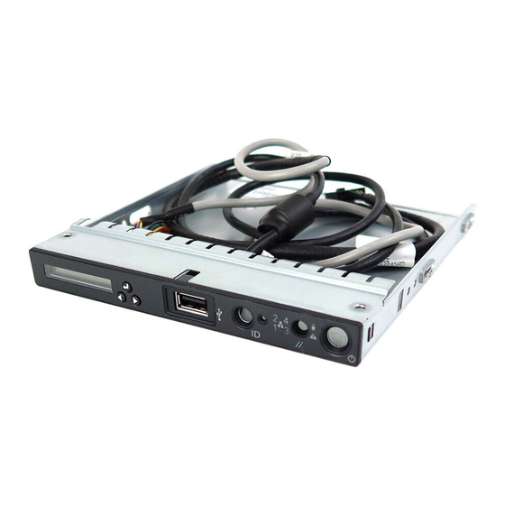
Physical and Electrical Description Intel® Local Control Panel for EPSD Platforms TPS System Components and Functions The LCD (Local Control Display) is a one line character display that resides on the LCP. It can display a maximum of 16 characters at a time. This device also contains three buttons (Left, Right, and Enter). -
Page 11: Electrical Description
Intel® Local Control Panel for EPSD Platforms TPS Physical and Electrical Description Label Description Functionality LCD Display one line 16 character display Left Control Button moves the cursor backward one step or one character Enter Button selects the menu item highlighted by the cursor... -
Page 12: Lcd Backlight Leds
Physical and Electrical Description Intel® Local Control Panel for EPSD Platforms TPS 2.3.3 LCD Backlight LEDs The LCD has two backlight colors (green and amber). Under normal conditions the backlight is to be driven green by the BMC. When a problem is detected with the server, the BMC will deactivate the green backlight and turns-on the amber backlight. -
Page 13: Firmware Functional Specification
Intel® Local Control Panel for EPSD Platforms TPS Firmware Functional Specification Firmware Functional Specification Overview LCD (Local Control Display) is a one line character display that resides on the front panel of a chassis. It can display maximum of 16 characters at a time. However, a few special characters such as {, }, `, ~, and ^ are not available in the current LCD controller supported set of characters. -
Page 14: Main Menu
Firmware Functional Specification Intel® Local Control Panel for EPSD Platforms TPS On pressing Enter button when the screen shows banner or error message, the Main Menu is displayed. The Main Menu contains Evt, View, and Conf items. Based on the user’s selection in the Main Menu, respective sub-menu items will be displayed. -
Page 15: View Menu
Intel® Local Control Panel for EPSD Platforms TPS Firmware Functional Specification displays the latest high severity event if one exists or System Health OK message if there are no active (asserted) errors in the system currently. If there are more than two active events in the system, then they are displayed in the descending order of their severity when menu item, ... -
Page 16: System Information (Si)
Firmware Functional Specification Intel® Local Control Panel for EPSD Platforms TPS 3.5.2 System Information (SI) Selecting SI item in the View menu displays the following screen. |SN|SM|AT|SGUID|CSTR Figure 14: System Information menu The menu items for the above screen are described below: ... -
Page 17: Power (Pow)
Intel® Local Control Panel for EPSD Platforms TPS Firmware Functional Specification 3.5.5 Power (Pow) Selecting Pow item in the View menu displays the amount of AC power drawn by the system in Watts. |xxxx W Figure 16: Power Consumed by the System Currently 3.5.6... -
Page 18: Figure 21: Screen Shot For Configuring Ip Address, Subnet Mask, And Gateway
Firmware Functional Specification Intel® Local Control Panel for EPSD Platforms TPS and the following screen is displayed on selecting any of IPAddr, SMask, and GWay items. The selected item will be set with the configured value once Set is selected in the following figure. -
Page 19: Rmm Lan (Rl) Configuration
Intel® Local Control Panel for EPSD Platforms TPS Firmware Functional Specification Left/ Right Increment/ Decrement Enter Enter Right Left Pos: Pos: Pos: Left Right Figure 22: State transition diagram for setting IP Address 3.6.2 RMM LAN (RL) Configuration Same screen shots and the same description as mentioned in BMC LAN (BL) Configuration are applicable for RMM LAN configuration menu also. - Page 20 CStr (Customizable String): Displays a customizable text string. The custom text string ® is modifiable through BIOS setup or a utility by using the Intel General Application (Net Function: 0x30) command 0xB3 (Write LCD Custom String). Intel order number G83726-001...
-
Page 21: Installing And Removing The Intel Local Control Panel
Local Control Panel bracket and secure the two screws (see letter E). ® 6. Connect the LCP cable to the LCP board and install the Intel Local Control Panel bracket into server chassis together with cables (see letter F). 7. Secure the two screws (see letter G). -
Page 22: Removing The Intel ® A1U2Ulcp Local Control Panel In A 1U Server System
Installing and Removing the Intel® Local Control Panel Intel® Local Control Panel for EPSD Platforms TPS ® Figure 26: Installing the Intel A1U2ULCP Local Control Panel in a 1U server system Removing the Intel A1U2ULCP Local Control Panel in a 1U server ®... -
Page 23: Figure 27: Removing The Intel A1U2Ulcp Local Control Panel In A 1U Server System
® Figure 27: Removing the Intel A1U2ULCP Local Control Panel in a 1U server system 5. Install the front USB connecter to the bracket and secure the two screws (see letter E). 6. Install the bracket together with cables (see letter F). -
Page 24: Installing The Intel ® A1U2Ulcp Local Control Panel In A 2U Server System
3. For 2U system with 2.5” hard drive configuration, remove the three screws to release the hard drive cage (see letter A). For 2U system with 3.5” hard drive configuration, remove ® the six screws to release the hard drive cage. Please refer to the Intel Server System Service Guide for detailed instructions. -
Page 25: Figure 30: Removing The Bracket In A 2U Server System
Local Control Panel bracket and secure the two screws (see letter G). ® 10. Connect the LCP cable to the LCP board and install the Intel Local Control Panel bracket into server chassis together with cables (see letter H). 11. Secure the two screws (see letter I). -
Page 26: Removing The Intel A1U2Ulcp Local Control Panel In A 2U Server System
4. For 2U system with 2.5” hard drive configuration, remove the three screws to release the hard drive cage (see letter B). For 2U system with 3.5” hard drive configuration, remove ® the six screws to release the hard drive cage. Please refer to the Intel Server System Service Guide for detailed instructions. -
Page 27: Figure 7: Intel
® Figure 34: Removing the Intel A1U2ULCP Local Control Panel in a 2U server system 9. Install the front USB connecter to the bracket and secure the two screws (see letter G). 10. Install the bracket together with cables (see letter H). -
Page 28: Figure 35: Installing The Bracket In A 2U Server System
14. Connect the front video cable, the front USB cable and the front panel cable to the server board (see letter L). Figure 36: Installing the cage in a 2U server system ® 15. Install the stiffener. Please refer to the Intel Server System Service Guide for detailed instructions. Intel order number G83726-001... -
Page 29: Installing The Intel A4Ulcp Local Control Panel In A Pedestal Server System
Intel® Local Control Panel for EPSD Platforms TPS Installing and Removing the Intel® Local Control Panel Installing the Intel A4ULCP Local Control Panel in a Pedestal server ® system 1. Remove the front panel cable and USB cable from motherboard (see letter A). -
Page 30: Removing The Intel ® A4Ulcp Local Control Panel In A Pedestal Server System
Installing and Removing the Intel® Local Control Panel Intel® Local Control Panel for EPSD Platforms TPS ® Figure 38: Installing the Intel A4ULCP Local Control Panel in a Pedestal server system Removing the Intel A4ULCP Local Control Panel in a Pedestal server ®... -
Page 31: Figure 39: Removing The Intel A4Ulcp Local Control Panel From A Pedestal Server System
Intel® Local Control Panel for EPSD Platforms TPS Installing and Removing the Intel® Local Control Panel ® Figure 39: Removing the Intel A4ULCP Local Control Panel from a Pedestal server system 4. Insert the front panel tray into the chassis (see letter H). -
Page 32: Replacing The Front Panel Board
Installing and Removing the Intel® Local Control Panel Intel® Local Control Panel for EPSD Platforms TPS Replacing the Front Panel Board 1. Observe the safety and Electro Static Discharge (ESD) precautions at the beginning of this document. 2. Remove the screw (see Letter A) securing the front panel board and remove the front panel board (see Letter B). -
Page 33: Appendix A: Installation/Assembly Safety Instructions
Intel® Local Control Panel for EPSD Platforms TPS Appendix A: Installation/Assembly Safety Instructions Appendix A: Installation/Assembly Safety Instructions Observe the following safety guidelines: Do not operate your computer system with any cover(s) (such as computer covers, bezels, filler brackets, and front-panel inserts) removed. - Page 34 Appendix A: Installation/Assembly Safety Instructions Intel® Local Control Panel for EPSD Platforms TPS Additional safety guidelines: When you disconnect a cable, pull the connector or the strain-relief loop, not the cable itself. Some cables have a connector with locking tabs; if you are disconnecting this type of cable, press in on the locking tabs before disconnecting the cable.
Need help?
Do you have a question about the A1U2ULCP and is the answer not in the manual?
Questions and answers